QQFPBTHST02C2CJBluetooth Wireless Headset
Windigo Systems
Click to zoom
Application Details
- Equipment Class
- DTS - Digital Transmission System
- Date of Grant
- Jan 20, 2003
- Application Purpose
- Original Equipment
- Date of Application
- Jan 20, 2003
- Equipment Note
- Bluetooth Wireless Headset
- Frequency Range
- 2402.00000000 - 2480.00000000
- Company
- Windigo Systems
- Country
- United States
Documents & Files
Document Text
Text extracted from the exhibit documents filed with the FCC. Open a document above to read the original.
Users Manual
LED Status Indicators Idle: No LEDs. Power saving mode. Standby: Green LED flashes every 2 secs. Headset ready to make/receive calls Make Call: Green LED on, red LED flashing – 0.5s Pairing: Red and green LEDs flash alternately Connected: Green LED permanently on This guide was prepared by: EskTech Ltd 24 Norfolk Road, Carlisle, Cumbria, UK, CA2 5PQ Tel: +44 (0) 1228 409098 Fax: +44 (0) 1228 409091 Email: [email protected] Web: www.esktech.com © EskTech Ltd 2002 Summary of Controls Controls: You can control the headset using the single, multifunction button. To check the status of the headset you need to view the two LEDs (one red, one green) and listen to the warning tones using the earpiece. Switch on: Press button once. The green LED will flash and a low-to-high tone will be heard. Switch off: Press button until a high-to-low tone is heard. Both LEDs switch off. Pairing: Press and hold the button for 8 seconds – until the green and red LEDs flash alternately – then release the button. Cancel Pairing: Press and hold the button for 8 seconds - until both LEDs are off – then release the button. Answer a Call: Press the button once. Reject a Call: Press and hold the button – until the ring tone stops. Mute: Slide and hold the button. Green and red LED on. Reset: Press and hold the button for 10 seconds. You will hear a rising then a falling tone. Both LEDs will flash on and off simultaneously. Volume Control: Rock the button in either direction to increase or decrease the volume . Bluetooth Headset Quick Start Guide for Mobile Phone Use Char g er socke t Ear p iece / mic. socke t Decorative rin g Status LEDs Multifunction button Introduction The Windigo Systems Bluetooth headset allows you to connect without cables to your mobile phone, PC or any Bluetooth device which supports the Headset profile. Your mobile phone can stay in your pocket or your briefcase and you can still make (if your phone supports voice-recognition) and receive calls. Provided the headset has been “paired” with your phone and is within a few metres of the phone or PC, the headset and phone should be able to connect together. What do I need for phone usage? You need a mobile phone that supports Bluetooth – such as the T39, T68, 6310, 7650 and many others. Getting Started 1. Charge the headset, using an appropriate charger for 3 hours 2. Pair the headset with your phone (Note: the first time the headset is turned on it will automatically be ready for pairing) 3. Alternatively, from the Idle state, press and hold the button for about 8 seconds until the green and red LEDs flash alternately. 4. Follow the instructions from your mobile phone manufacturer for pairing. 5. Enter PIN CODE: 8888 into your phone when prompted. 6. Successful pairing is indicated by the red LED going off and the green LED will flash every 2 seconds. 7. The phone will also indicate pairing status and “BTHS” should be visible on the phone’s display of paired devices. The headset is now ready to make / receive calls and will ring whenever there is an incoming call. (Note: Your mobile phone has to be enabled for hands-free operation) Answering an incoming call When the headset rings simply press the button to answer the call. The green LED will be permanently on once the call is connected. Reject an incoming call When the headset rings simply press and hold the button until the ringing stops To m a k e a c a l l Your mobile phone must support voice dialling to use this function. Press the button once. The green LED will stay on and the red LED will flash at 0.5 second intervals. Talk into the microphone and, once the call is established, the red LED will go off. Adjusting the volume Rock the button to one side or the other to increase or decrease the volume. Mute / un-mute the microphone The mute function allows you to consult with someone next to you without dropping the call. Rock and hold the volume button for 6 seconds. Both the green and red LEDs will go on. The microphone of the headset is now disabled. Repeat the operation to un-mute. The red LED will go off. Notes: 1. Default Name: BTHS 2. PIN Code: 8888 3. Headset can only talk to one phone at a time after successful pairing. 4. Pairing mode can be cancelled by pressing and holding the button for about 8 seconds until both LEDs are off and a high-to-low tone is heard. The headset is now idle. Federal communications Commission This device complies with Part 15 of the FCC Rules. Operation is subject to the following two conditions:(1) this device may not cause harmful interference, and (2) this device must accept any interference received, including interference that may cause undesired operation. NOTE: This equipment has been tested and found to comply with the limits for a Class B digital device, pursuant to Part 15 of the FCC Rules. These limits are designed to provide reasonable protection. This equipment generates, uses and can radiated radio frequency energy and, if not installed and used in accordance with the instructions, may cause harmful interference to radio communications. However, there is no guarantee that interference will not occur in a particular installation If this equipment does cause harmful interference to radio or television reception, which can be determined by turning the equipment off and on, the user is encouraged to try to correct the interference by one or more of the following measures: -Reorient or relocate the receiving antenna. -Increase the separation between the equipment and receiver. -Connect the equipment into an outlet on a circuit different from that to which the receiver is connected. -Consult the dealer or an experienced radio/TV technician for help. Changes or modifications not expressly approved by the party responsible for compliance could void the user‘s authority to operate the equipment. This device and its antenna must not be co-located or operating in conjunction with any other antenna or transmitter. Copyright Windigo Systems Inc. 2002 in…
Text truncated - open the document above for the full version.
External Photos
FCC ID : QQFPBTHST02C2CJ FRONT SIDE OF EUT Number 1 FCC ID : QQFPBTHST02C2CJ REAR SIDE OF EUT Number 2
ID Label/Location Info
6mm 25mm This statement will be placed in User Manual. This device complies with part 15 of the FCC Rules. Operation is subject to the following two conditions: (1) this device may not cause harmful interference, and (2) this device must accept any interference received, including interference that may cause undesired operation. Windigo Systems Model:PBTHST02C2CJ FCC ID:QQFPBTHST02C2CJ CE 0470
Internal Photos
FCC ID : QQFPBTHST02C2CJ Number 1 Mechanical Construction FCC ID : QQFPBTHST02C2CJ Number 2 Mechanical Construction FCC ID : QQFPBTHST02C2CJ Number 3 Front side of Main Board FCC ID : QQFPBTHST02C2CJ Number 4 Rear side of Main Board FCC ID : QQFPBTHST02C2CJ Number 5 Side side of Adaptor FCC ID : QQFPBTHST02C2CJ Number 6 Side side of Adaptor FCC ID : QQFPBTHST02C2CJ Number 7 Front side of Adaptor FCC ID : QQFPBTHST02C2CJ Number 8 USB Cable
Operational Description
Operation Description: Windigo Bluetooth headset is battery power wireless communication device used to transfer both control command and voice between headset and audio gateway device, which is Bluetooth specification V1.1 compliant, and a single chip RF transceiver from Cambridge Silicon Radio is used. Single 16MHz crystal is used for both generating the timing for Bluetooth communication and internal micro-controller. PCB antenna is built in. This Bluetooth headset is major used with cellular phone for hand-free kit, but also can be used with Bluetooth capable computer, notebook, PDA and other computing and communication devices. On the RF side, frequency-hopping technology is used, and hopping rate is at 1600 hops per second over 79 channels. Channel spacing is 1MHz, and operating at 2.400-2.485GHz. GFSK (Gaussian Frequency Shit Keying) modulation method is used. Raw data rate is up to 721kbps. Whole system includes the following functional blocks: Audio Jack Audio jack provides the analog interface for microphone and speaker, includes microphone input signal and speaker output signal. Buttons Buttons are used to perform pre-defined operation with interactive with user. Three buttons are defined, including talk button, volume up button and volume down button DC Jack DC jack is used to charge the battery inside headset, and the designed input voltage is 6V DC Charging Protection Charging protection is used to control the charging voltage and charging current to make sure the battery can be charged quickly and safely LEDs LEDs are used to indicate various internal statuses for headset, like pairing mode, talking mode, standby mode etc. CODEC CODEC is used to convert audio signal between digital and analog. Bluetooth Module Bluetooth Module performs all the Bluetooth functions from RF transmit and receive to communication protocol, also the man-machine interface operation, including buttons control and LED control Antenna Antenna is the unit to send the signal to air, and it receives the signal from air and feeds into Bluetooth Module Typical usage scenario for Windigo Bluetooth Headset A typical Windigo Bluetooth headset usage scenario is to use the headset with a Bluetooth enabled cellular phone (handset). Before the headset can be used, a pairing procedure has to be carried out by pressing the button on headset to put the headset into pairing mode, and then initialize the pairing procedure on cellular phone. After the headset and cellular phone is paired, then the headset is ready to use for normal operation. When there is an incoming call, cellular phone will make a data connection over Bluetooth with headset, and then send the ring command to headset. Once the headset receives the ring indication, it will alert user about this incoming call, user can press talk button to answer the call, then a voice connection is established between headset and cellular phone.
Test Report
FCC TEST REPORT Report No. : F2N0612 SPORTON International Inc. TEL : 886-2-2696-2468 FAX : 886-2-2696-2255 FCC TEST REPORT for 47 CFR, Part 15, Subpart C Equipment : Bluetooth Wireless Headset Model No. : PBTHST02C2CJ, Blue-Talk 01 FCC ID : QQFPBTHST02C2CJ Filing Type : Certification Applicant : Windigo Systems 2210 O’Toole Ave, Suite 200, San Jose, CA 95131, U.S.A. † The test result refers exclusively to the test presented test model / sample. † Without written approval of SPORTON International Inc., the test report shall not be reproduced except in full. † Certificate or Test Report must not be used by the applicant to claim the product in this test report endorsement by NVLAP or any agency of U.S. government. SPORTON International Inc. 6F, No.106, Sec. 1, Hsin Tai Wu Rd., Hsi Chih, Taipei Hsien, Taiwan, R.O.C. FCC TEST REPORT Report No. : F2N0612 SPORTON International Inc. FCC ID : QQFPBTHST02C2CJ TEL : 886-2-2696-2468 Page No. : i FAX : 886-2-2696-2255 Issued Date : Dec. 23, 2002 Table of Contents History of this test report.........................................................................................................ii CERTIFICATE OF COMPLIANCE..............................................................................................................2 1. General Description of Equipment under Test.....................................................................................3 1.1. Applicant.......................................................................................................................................................................................3 1.2. Manufacturer.................................................................................................................................................................................3 1.3. Basic Description of Equipment under Test...................................................................................................................................3 1.4. Feature of Equipment under Test..................................................................................................................................................3 2. Test Configuration of Equipment under Test.......................................................................................5 2.1. Test Manner..................................................................................................................................................................................5 2.2. Description of Test System...........................................................................................................................................................5 2.3. Connection Diagram of Test System.............................................................................................................................................6 3. General Information of Test.................................................................................................................7 3.1. Test Facility...................................................................................................................................................................................7 3.2. Test Voltage..................................................................................................................................................................................7 3.3. Standard for Methods of Measurement.........................................................................................................................................7 3.4. Test in Compliance with................................................................................................................................................................7 3.5. Frequency Range Investigated......................................................................................................................................................7 3.6. Test Distance................................................................................................................................................................................7 3.7. Test Modes...................................................................................................................................................................................7 4. Report of Measurements and Examinations........................................................................................8 4.1. List of Measurements and Examinations.......................................................................................................................................8 4.2. Hopping Channel Separation........................................................................................................................................................9 4.3. Number of Hopping Frequency...................................................................................................................................................13 4.4. Hopping Channel Bandwidth.......................................................................................................................................................15 4.5. Dwell Time of Each Frequency within a 30 Seconds Period.......................................................................................................19 4.6. Output Power..............................................................................................................................................................................23 4.7. 100KHz Bandwidth of Frequency Band Edges............................................................................................................................24 4.8. Test of Conducted Emission........................................................................................................................................................27 4.9. Test of Radiated Emission.......................…
Text truncated - open the document above for the full version.
Test Setup Photos
FCC TEST REPORT Report No. : F2N0612 SPORTON International Inc. FCC ID : QQFPBTHST02C2CJ TEL : 886-2-2696-2468 Page No. : 1 of 3 FAX : 886-2-2696-2255 Issued Date : Dec. 23, 2002 1.1. Photographs of Conducted Emission Test Configuration n The photographs show the configuration that generates the maximum emission. FRONT VIEW REAR VIEW FCC TEST REPORT Report No. : F2N0612 SPORTON International Inc. FCC ID : QQFPBTHST02C2CJ TEL : 886-2-2696-2468 Page No. : 2 of 3 FAX : 886-2-2696-2255 Issued Date : Dec. 23, 2002 SIDE VIEW FCC TEST REPORT Report No. : F2N0612 SPORTON International Inc. FCC ID : QQFPBTHST02C2CJ TEL : 886-2-2696-2468 Page No. : 3 of 3 FAX : 886-2-2696-2255 Issued Date : Dec. 23, 2002 1.2. Photographs of Radiated Emission Test Configuration n The photographs show the configuration that generates the maximum emission. FRONT VIEW REAR VIEW
Contact Information
Applicant
Lim Huat Seng(CEO)
Test Firm
SPORTON International IncKathy Lin
Technical Specifications
| # | Rule Parts | Frequency Range | Power Output |
|---|---|---|---|
| 1 | 15C | 2.40 GHz - 2.48 GHz | 3.00 mW |
Other Applications from Windigo Systems

QQFPBTMAYZC2-X
Nov 13, 2005Bluetooth Headset with Music Controller
Equipment Class
DSS - Part 15 Spread Spectrum Transmitter
QQFPBTCRMRYC2-X
Aug 21, 2005USB Bluetooth Adapter
Equipment Class
DSS - Part 15 Spread Spectrum Transmitter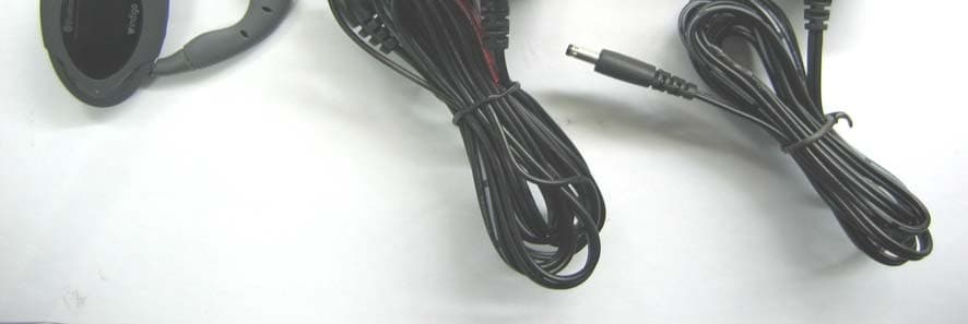
QQFPBTOIDX2C2X
Jun 28, 2005Bluetooth Headset
Equipment Class
DSS - Part 15 Spread Spectrum TransmitterQQFPBTFABX2C2X
Oct 10, 2004Bluetooth Headset
Equipment Class
DSS - Part 15 Spread Spectrum Transmitter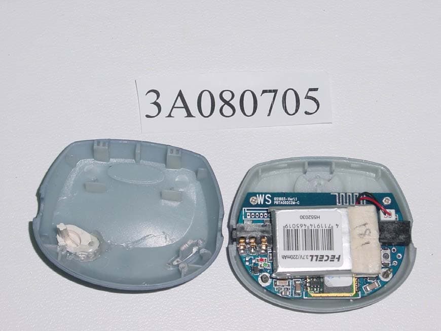
QQFPBTAG02C2
Nov 20, 2003Bluetooth Audio Gateway
Equipment Class
DSS - Part 15 Spread Spectrum Transmitter