QQFPBTHSTF2C2EBluetooth Earphone
Windigo Systems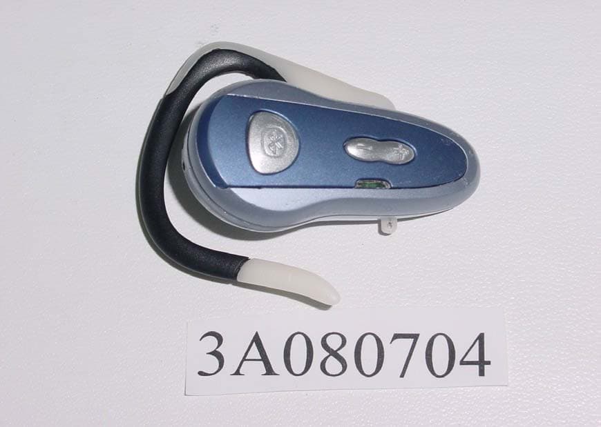
Click to zoom
Application Details
- Equipment Class
- DSS - Part 15 Spread Spectrum Transmitter
- Date of Grant
- Nov 20, 2003
- Application Purpose
- Original Equipment
- Date of Application
- Nov 20, 2003
- Equipment Note
- Bluetooth Earphone
- Frequency Range
- 2402.00000000 - 2480.00000000
- Company
- Windigo Systems
- Country
- United States
Documents & Files
Document Text
Text extracted from the exhibit documents filed with the FCC. Open a document above to read the original.
Users Manual
Confidential Page 1 5/8/2003 2210 O’Toole Ave. #200, San Jose, Ca. 95131 Tel: 408-576-1770 Fax: 408-576-1790 2210 O'Toole Ave #200 San Jose, CA 95131 TEL : 408.576.1770 FAX : 408.576.1790 [email protected] http://www.windigosys.com/ Windigo Products Windigo Bluetooth(TM) Headset User manual (Mini Headset Module) PBTHSTA2C2M Ver.1.2 Wednesday, May 07, 2003 Confidential Page 2 5/8/2003 2210 O’Toole Ave. #200, San Jose, Ca. 95131 Tel: 408-576-1770 Fax: 408-576-1790 FEDERAL COMMUNICATIONS COMMISSION This device complies with Part 15 of the FCC Rules. Operation is subject to the following two conditions:(1) this device may not cause harmful interference, and (2) this device must accept any interference received, including interference that may cause undesired operation. NOTE This equipment has been tested and found to comply with the limits for a Class B digital device, pursuant to Part 15 of the FCC Rules. These limits are designed to provide reasonable protection. This equipment generates, uses and can radiated radio frequency energy and, if not installed and used in accordance with the instructions, may cause harmful interference to radio communications. However, there is no guarantee that interference will not occur in a particular installation If this equipment does cause harmful interference to radio or television reception, which can be determined by turning the equipment off and on, the user is encouraged to try to correct the interference by one or more of the following measures: -Reorient or relocate the receiving antenna. -Increase the separation between the equipment and receiver. -Connect the equipment into an outlet on a circuit different from that to which the receiver is connected. -Consult the dealer or an experienced radio/TV technician for help. Shielded interface cables must be used in order to comply with emission limits. Changes or modifications not expressly approved by the party responsible for compliance could void the user‘s authority to operate the equipment. Confidential Page 3 5/8/2003 2210 O’Toole Ave. #200, San Jose, Ca. 95131 Tel: 408-576-1770 Fax: 408-576-1790 1. Introduction Bluetooth profile K-6 gives an implementation guideline for Bluetooth headset application, which includes two functions: Bluetooth headset and Bluetooth audio gateway. Generally headset profile will be implemented in headset, and audio gateway will be implemented in cellular phone, PBX or other communication devices. Windigo systems has developed a fully Bluetooth V1.1 compliant headset module. This manual will explain the basic headset operation instruction to our customers. 2. A glimpse at the headset Figure 1 illustrates the reference headset and cellular phone. Figure 1. Windigo Bluetooth Headset Reference Design The headset module includes an amber LED, a blue LED, three buttons, and embedded audio connections and charging contact, these elements are illustrated in figure 2. Figure 2. Key elements on Windigo Bluetooth Headset Both amber LED and blue LED are used to indicate various operation status for the headset, such as pairing, connecting, talking...etc. Talk Button Amber LED Blue LED Volume Up Volume Down Fig. 1.a PBTHSTA2C2M – Top View Fig1.b PBTHSTA2C2M- Bottom View Confidential Page 4 5/8/2003 2210 O’Toole Ave. #200, San Jose, Ca. 95131 Tel: 408-576-1770 Fax: 408-576-1790 The three buttons are used to initialize various operations, such as activating the headset, turning off the headset, pairing, connecting, etc. Audio connections are used to connect an external microphone and speaker. Windigo Bluetooth Headset must be paired with an audio gateway before it is fully functional. Please refer to the audio gateway user manual on how to initialize and operate the audio gateway and its various functions. 3. Getting start Step 1: Be sure the headset battery is fully charged before the first time use. (Charging time is about 2 hours) Step 2: Enter into pairing (discoverable and connectable) mode During headset transportation, headset is on idle (deep sleep) mode to conserve battery power. While in this idle mode, both blue and amber LEDs are off. To enable the pairing mode, press and hold the talk button until blue and amber LED flash alternatively, and a PAIR tone will be heard. This press and hold time is about 5 seconds. Please be noted that before blue and amber LED flash alternatively, either blue or amber LED will flash shortly depends on the battery status, and an ON tone will be heard. So in order to enter into pairing mode correctly, please still hold the talk button. After the PAIR tone is heard, and blue and amber LED flash alternatively, then release the button. Note: 1. Default headset name is BTHS03, and pin code is 0000 2. Pairing feature is used to establish the relationship between headset and audio gateway. Any given headset can only talk with the paired audio gateway after a successful pairing session. 3. Pairing mode can be cancelled by pressing and holding the talk button for about 3 seconds, until both amber LED and blue LED are off, and the OFF tone is heard. Then the headset is put into idle mode again. 4. Follow the instruction for specific audio gateway to perform the pairing. If the headset has been paired with audio gateway successfully, the headset will enter into standby (connectable only) mode. During this mode, blue LED will flash at 1-second interval if battery is full, and amber LED is off. Otherwise, if battery is low, then amber LED will flash at 1-second interval and blue LED will be off. Step 3: Now the headset is ready to use. The headset will ring whenever there is an incoming call. Confidential Page 5 5/8/2003 2210 O’Toole Ave. #200, San Jose, Ca. 95131 Tel: 408-576-1770 Fax: 408-576-1790 Step 4: Answering the incoming call. When the headset is ringing, user can pick up the call by pressing the talk button once shortly. Note: Make sure the cellular phone has been configured correctly so an incoming call is transferred to the headset via Blu…
Text truncated - open the document above for the full version.
Cover Letter(s)
Windigo Systems August 6, 2003 Federal Communications Commission Authorization and Evaluation Division FCC ID: PBTHSTF2C2E Confidentiality Request Pursuant to Sections 0.457 and 0.459 of the Commission’s Rules, the Applicant hereby requests confidential treatment of information accompanying this Application as outlined below: 1. Schematics 2. Operational Description 3. Block Diagram The above materials contain trade secrets and proprietary information not customarily released to the public. The public disclosure of these matters might be harmful to the Applicant and provide unjustified benefits to its competitors. The Applicant understands that pursuant to Rule 0.457, disclosure of this Application and all accompanying documentation will not be made before the date of the Grant for this application. Sincerely, (Singer Name) / (Title) Windigo Systems
Cover Letter(s)
Address: 2210 O'Toole Ave,Suite 200 San Jose,CA 95313 USA. Telephone: 408576-1779 FAX: 408576-1790 PHOENIX TEST-LAB GmbH Product Certification Königswinkel 10 0 32825 BIomberg Ta Wham It May Cancern: Please be advised that Windigo Systems authorizes Interocean EMC Technology Corp to act on Dur behalf, until otherwise notified, for applications submitted to PHOENIX TEST-LAB GmbH (PTL). We certify that we are not subject to denial of federal benefits, that includes FCC benefits, pursuant to Section 5301 of the Anti-Drug Abuse ACT of 1988, U.S.C.862. Further, no party, as defined in 47 CFR 1.2002 (b), to the application is subject to denial of federal benefits, that includes FCC benefits. Thank you for your attention to this matter. Signatory -:\. Ersteller: U. Rodemeier Erstelldatum: 3. August 2001 Seite 1 von 1 Revision: 00 Datum: 3. August 2001 C:\ TEMPlC Prog ramme Notes. pbccO2. Data IAppl icantLetter Agent(W indi go ). doc
External Photos
Report No.: 3A080704FR FCC ID: QQFPBTHSTF2C2E Page 51 of 60 Interocean EMC Technology Corp. FCC EMC Test Report 14 Photographs of EUT Front View of Appearance (PBTHSTF2X2-ELC) Rear View of Appearance (PBTHSTF2X2-ELC) Report No.: 3A080704FR FCC ID: QQFPBTHSTF2C2E Page 52 of 60 Interocean EMC Technology Corp. FCC EMC Test Report Left View of EUT (PBTHSTF2X2-ELC) Front View of EUT (PBTHSTF2X2-ELE)
ID Label/Location Info
10mm 15mm This statement will be placed in User Manual. This device complies with part 15 of the FCC Rules. Operation is subject to the following two conditions: (1) this device may not cause harmful interference and (2) this device must accept any interference received, including interference that may cause undesired operation.
Internal Photos
Report No.: 3A080704FR FCC ID: QQFPBTHSTF2C2E Page 53 of 60 Interocean EMC Technology Corp. FCC EMC Test Report Inside View of EUT Report No.: 3A080704FR FCC ID: QQFPBTHSTF2C2E Page 54 of 60 Interocean EMC Technology Corp. FCC EMC Test Report Component Side of Main board Solder Side of Main board PCB Antenna Report No.: 3A080704FR FCC ID: QQFPBTHSTF2C2E Page 55 of 60 Interocean EMC Technology Corp. FCC EMC Test Report Top View of Cradle Port View of Cradle Report No.: 3A080704FR FCC ID: QQFPBTHSTF2C2E Page 56 of 60 Interocean EMC Technology Corp. FCC EMC Test Report Bottom View of Cradle Inside View of Cradle Report No.: 3A080704FR FCC ID: QQFPBTHSTF2C2E Page 57 of 60 Interocean EMC Technology Corp. FCC EMC Test Report Component View of Main Board (Cradle) Solder View of Main Board (Cradle) Report No.: 3A080704FR FCC ID: QQFPBTHSTF2C2E Page 58 of 60 Interocean EMC Technology Corp. FCC EMC Test Report Front View of Power Adapter Rear View of Power Adapter Report No.: 3A080704FR FCC ID: QQFPBTHSTF2C2E Page 59 of 60 Interocean EMC Technology Corp. FCC EMC Test Report Label of Power Adapter Inside View of Power Adapter Report No.: 3A080704FR FCC ID: QQFPBTHSTF2C2E Page 60 of 60 Interocean EMC Technology Corp. FCC EMC Test Report Component Side of Main board (Power Adapter) Solder Side of Main board (Power Adapter)
Test Report
Report No.: 3A080704FR FCC ID: QQFPBTHSTF2C2E Page 1 of 61 Interocean EMC Technology Corp. FCC EMC Test Report FCC Part 15 EMI TEST REPORT of E.U.T.:Bluetooth Earphone Trade Name: Windigo Systems; V3; EIO WaveLinker; MAXCALL; PMR Model Number: PBTHSTX2C2-XXX; BTH1; BTH2; AP-7802; KBU005B (X=A~Z, 0~9 or Blank) Prepared for Prepared by Interocean EMC Technology Corp. No.5-2, Lin 1, Tin-Fu Tsun, Lin-Kou Hsiang, Taipei County, Taiwan, R.O.C. TEL.: +886 2 2600 6861 FAX.: +886 2 2600 6859 Remark: The test report consists of 61 pages in total. It shall not be reproduced except in full, without the written approval of IETC. This document may be altered or revised by IETC only, and shall be noted in the revision section of the document. The test results in the report only to the tested sample. Windigo Systems 2210 O ’ Toole Ave Suite 200, San Jose, CA 95131, U.S.A. TEL: +408 576 1779 FAX: +408 576 1790 Report No.: 3A080704FR FCC ID: QQFPBTHSTF2C2E Page 3 of 61 Interocean EMC Technology Corp. FCC EMC Test Report Table of Contents 1 General Information 6 1.1 Description of Equipment Under Test 6 1.2 Tested Supporting System Detail 7 1.3 Test Methodology 7 1.4 Bluetooth Approvals 7 1.5 Test Facility 7 2 PROVISIONS APPLICABLE 8 2.1 Definition 8 2.2 Requirement for Compliance 9 2.3 Restricted Bands of Operation 11 2.4 Labeling Requirement 12 2.5 User Information 12 2.6 Supporting System Detail (For Radiation Emission Measurement) 13 3 SYSTEM TEST CONFIGURATION 14 3.1 Justification 14 4 Power Line Conducted Emission Measurement 15 4.1 Instrument 15 4.2 Block Diagram of Test Configuration 15 4.3 Conducted Limit (Power Line) 16 4.4 Measurement Procedure 16 4.5 Measuring Instrument 16 4.6 Test Step of EUT 16 5 RADIATED EMISSION MEASUREMENT 21 5.1 Instrument 21 5.2 Block Diagram of Test Configuration 21 5.3 Applicable Standard 22 5.4 Measurement Procedure 22 5.5 Measuring Instrument 23 5.6 Test Step of EUT 23 5.7 Radiated Emission Data 24 5.8 Field Strength Calculation 31 6 ANTENNA REQUIREMENT 32 6.1 Standard Applicable 32 Report No.: 3A080704FR FCC ID: QQFPBTHSTF2C2E Page 4 of 61 Interocean EMC Technology Corp. FCC EMC Test Report 6.2 Antenna Construction and Directional Gain 32 7 HOPPING CHANNEL BANDWIDTH MEASUREMENT 33 7.1 Standard Applicable 33 7.2 Measurement Procedure 33 7.3 Measurement Equipment 33 7.4 Measurement Data 33 8 MAXIMUM OUTPUT POWER MEASUREMENT 34 8.1 Standard Applicable 34 8.2 Measurement Equipment 34 8.3 Measurement Data 34 9 100 kHz BANDWIDTH OF BAND EDGES MEASUREMENT 35 9.1 Standard Applicable 35 9.2 Measurement Procedure 35 9.3 Measurement Equipment 35 9.4 Measurement Data 35 10 HOPPING CHANNEL SEPARATION 36 10.1 Standard Applicable 36 10.2 Measurement Procedure 36 10.3 Measurement Equipment 36 10.4 Measurement Data 36 11 NUMBER OF HOPPING FREQUENCY USED 37 11.1 Standard Applicable 37 11.2 Measurement Procedure 37 11.3 Measurement Equipment 37 11.4 Measurement Data 37 12 DWELL TIME ON EACH CHANNEL 38 12.1 Standard Applicable 38 12.2 Measurement Procedure 38 12.3 Measurement Equipment 38 12.4 Bluetooth operation modes 39 12.5 Measurement Data 39 13 HOPPING SEQUENCE TEST 40 14 Receiver input bandwidth 40 A1.1 Mode 1: Charge Mode 41 Report No.: 3A080704FR FCC ID: QQFPBTHSTF2C2E Page 5 of 61 Interocean EMC Technology Corp. FCC EMC Test Report A1.2 Mode 2: TX/RX Mode 42 15 Photographs of Measurement 50 15.1 Power Line Conducted Emission Measurement 50 15.2 Radiated Emission Measurement 51 16 Photographs of EUT 52 Report No.: 3A080704FR FCC ID: QQFPBTHSTF2C2E Page 6 of 61 Interocean EMC Technology Corp. FCC EMC Test Report 1 General Information 1.1 Description of Equipment Under Test Equipment Under Test : Bluetooth Earphone Model Number : PBTHSTX2C2-XXX; BTH1; BTH2; AP-7802; KBU005B (X=A~Z, 0~9 or Blank) Serial Number : N/A Type of Sample Tested : Proto-type Pre-Production Mass Production Applicant : Windigo Systems 2210 O ’ Toole Ave Suite 200, San Jose, CA 95131, U.S.A. Manufacturer : Wearnes Electronics (M) Sdn Bhd 99, Jalan Parit Masjid, 82000 Pontian, Johor, Malaysia. Power Adapter : Manufacturer: BALANCE ELECTRONICS, M/N: GPSA-0750150 Input: 100-240Vac, 50-60Hz, 0.5A Output: 7Vdc, 0.6A Power cable: Non-shielded Detachable, 1.8m Date of Receipt of Sample : Aug. 18, 2003 Date of Test : Aug. 18 ~ Oct. 15, 2003 Description of E.U.T. : 1. The EUT contains a bluetooth Earphone and a cradle and an adapter. 2. Model Numbers (list on this report) are identical, except trade name. (PBTHSTX2C2-XXX series for Windigo Systems and PMR; BTH1; BTH2 for V3; AP-7802 for EIO WaveLinker; KBU005B for MAXCALL) 3. Windigo Bluetooth headset is battery power wireless communication device used to transfer both control command and voice between headset and audio gateway device, which is Bluetooth specification V1.1 compliant, and a single chip RF transceiver from Cambridge Silicon Radio is used. Single 16MHz crystal is used for both generating the timing for Bluetooth communication and internal micro-controller. PCB antenna is built in. The Antenna Max Gain is 2.5dBi. This Bluetooth headset is major used with cellular phone for handsfree kit, but also can be used with Bluetooth capable computer, notebook, PDA and other computing and communication devices. 4. EUT Ports: 1 Cradle Connect Port * 1. (on Earphone) 2 Earphone Connect Port * 1. (on Cradle) 3 Power Port * 1. (on Cradle) 5. The PBTHSTF2C2-ELC is representative selected in the test and included in this report. Report No.: 3A080704FR FCC ID: QQFPBTHSTF2C2E Page 7 of 61 Interocean EMC Technology Corp. FCC EMC Test Report 1.2 Tested Supporting System Detail z IBM Note Book Model Number : 2655-GT1 Serial Number : 78-LRZR4 EMC Approved : FCC DoC, CE, VCCI, 檢磁 3902I050 Manufacturer : IBM Adapter : IBM AA21070, 檢磁 3892A299 Input: 100-240Vac, 1.2~0.5A, 50/60Hz Non-shielded, Detachable, 1.5m Output: 16Vdc, 4.5A Non-shielded, Un-detachable, 1.8m z Audio Gateway Model Number : PBTAG02C2-1 Serial Number : N/A EMC Approved : QQFPBTAG02C2XXX Manufacturer : Windigo …
Text truncated - open the document above for the full version.
Test Setup Photos
Report No.: 3A080704FR FCC ID: QQFPBTHSTF2C2E Page 49 of 60 Interocean EMC Technology Corp. FCC EMC Test Report 13 Photographs of Measurement 13.1 Power Line Conducted Emission Measurement Front View Rear View Report No.: 3A080704FR FCC ID: QQFPBTHSTF2C2E Page 50 of 60 Interocean EMC Technology Corp. FCC EMC Test Report 13.2 Radiated Emission Measurement Front View Rear View
Contact Information
Applicant
Lim Huat Seng(CEO)
Technical Contact
Windigo SystemsQinton Yuan
[email protected]408 576 1779
2210 O'Toole Ave · San Jose, California · United States
Test Firm
Interocean EMC Technology Corp.Mike Huang
Technical Specifications
| # | Rule Parts | Frequency Range | Power Output |
|---|---|---|---|
| 1 | 15C | 2.40 GHz - 2.48 GHz | 721.00 µW |
Other Applications from Windigo Systems

QQFPBTMAYZC2-X
Nov 13, 2005Bluetooth Headset with Music Controller
Equipment Class
DSS - Part 15 Spread Spectrum Transmitter
QQFPBTCRMRYC2-X
Aug 21, 2005USB Bluetooth Adapter
Equipment Class
DSS - Part 15 Spread Spectrum Transmitter
QQFPBTOIDX2C2X
Jun 28, 2005Bluetooth Headset
Equipment Class
DSS - Part 15 Spread Spectrum TransmitterQQFPBTFABX2C2X
Oct 10, 2004Bluetooth Headset
Equipment Class
DSS - Part 15 Spread Spectrum Transmitter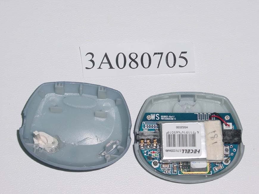
QQFPBTAG02C2
Nov 20, 2003Bluetooth Audio Gateway
Equipment Class
DSS - Part 15 Spread Spectrum Transmitter