QS3RB4RP1WIRELESS ROUTER
TwinMOS Technologies Inc.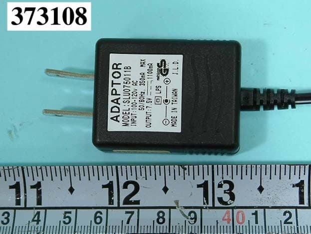
Click to zoom
Application Details
- Equipment Class
- DTS - Digital Transmission System
- Date of Grant
- Sep 25, 2003
- Application Purpose
- Original Equipment
- Date of Application
- Sep 25, 2003
- Equipment Note
- WIRELESS ROUTER
- Frequency Range
- 2412.00000000 - 2462.00000000
- Company
- TwinMOS Technologies Inc.
- Country
- Taiwan
Documents & Files
Document Text
Text extracted from the exhibit documents filed with the FCC. Open a document above to read the original.
Users Manual
TwinMOS Booming 802.11b Wireless Router User’s Manual TwinMOS ® Wireless Router TwinMOS Page 1 Contents PACKAGE CONTENTS..............................................................2 INTRODUCTION..........................................................................3 DESCRIPTION OF HARDWARE..........................................................4 BASIC INSTALLATION PROCEDURE..................................................6 CONNECTING THE AP ROUTER............................................................9 WEB MANAGEMENT SETTINGS..........................................................13 TROUBLESHOOTING.........................................................27 GLOSSARY........................................................................................................29 TECHNICAL SPECIFICATIONS............................................33 FCC CAUTION ........................................................................................34 Wireless Router TwinMOS Page 2 PACKAGE CONTENTS Unpack your Booming AP Router kit and verify that all items are present. z Booming Wireless Router z User’s Manual (on CD) z Power Adapter (7.5V/1.1A) z Antenna If any of the items described appear to be damaged or missing, please contact your reseller. Wireless Router TwinMOS Page 3 INTRODUCTION Thank you for purchasing the Wireless Router. The Wireless Router is an ideal broadband sharing solution for SOHO and home networks, featuring a wireless LAN function that reduces the necessity of connecting stations via a wired LAN. The Wireless Router manages all IP address assignments by DHCP, relieving users of the necessity of manually configuring clients for inter-client communication and access to the Internet. A built-in firewall provides extra security from malicious attack. The intuitive Web browser interface enables users to configure all aspects of the router, including making LAN, WAN, and WLAN settings, making access restrictions, setting administrative and user passwords. This Booming Wireless Router supports following features z Compatible with IEEE 802.11b Direct Sequence high data rate specifications. z Supports high-speed wireless connections up to 11 Mbps z Easy setup through a Web browser on any operating system that supports TCP/IP. z 10 Mbps WAN port connection to xDSL/Cable modem. z Four 10/100 Mbps Ethernet switch ports. z DHCP for dynamic IP configuration, and DNS for domain name mapping. z 64/128-bit Wired Equivalent Privacy (WEP) data encryption. z Web-based firmware upgrade Wireless Router TwinMOS Page 4 Description of Hardware Front Panel The front panel provides LED’s for device status. Refer to the following table for the meaning of each feature. LED State Color Meaning On Green The device is receiving power. Power Off ━ The device is not receiving power. WLAN Link On Green Indicates that the device is connected to WLAN. On Red Indicates WLAN status. WLAN Tx/Rx Blinking Red Indicates WLAN traffic. 10/100 On Red Indicates link speed(10/100 Mbps) On Green Link is established. On Flashing GreenPacket transmit or receive activity. Act Off ━ No link activity. Wireless Router TwinMOS Page 5 Rear Panel Item Description LAN ports The four RJ-45 Ethernet ports allow you to con-nect client PCs or LAN hubs to the Wireless Router. WAN port WAN port (RJ-45). Connect your Cable modem, xDSL modem, or an Ethernet router to this port. Power port Connect the included power adapter to this inlet. Warning: The included power adapter is DC 7.5V/1.1A. Using the wrong type of power adapter may cause damage. Antenna Two antennas provide wireless LAN functionality and ensure optimal signal strength. Reset button(Side) Use this button to reset the power and restore the default factory settings by pressing this button for five seconds. Wireless Router TwinMOS Page 6 Basic Installation Procedure Connecting the Router to the LAN You can connect the WLAN 11b Router to your PC, a hub, or a switch. Run the Ethernet cable from one of the LAN ports on the rear of the WLAN 11b Router to your computer’s network adapter or to another network device. You can also connect the WLAN 11b Router to your PC or to a client adapter via radio signals. Position one antenna on the back of the WLAN 11b Router into the desired positions. Connecting the Router to the WAN Prepare an Ethernet cable for connecting the WLAN 11b Router to a Cable/xDSL modem or Ethernet router. Wireless Router TwinMOS Page 7 Internal xDSL/Cable modem Power On Connect the power adapter to the WLAN 11b Router. SOHO/Home Networking WAN Wireless Router TwinMOS Page 8 Wireless Office Networking LAN Wireless Router TwinMOS Page 9 CONNECTING THE AP ROUTER Follow the procedure below to connect the AP Router. LAN connecting z Plug a Ethernet cable into a free LAN port at the rear of the router. Plug the other end of the cable into the RJ-45 port on your computer. z Turn on power supply for AP Router. z Setting TCP/IP to work with the AP Router. ¾ Windows XP 1. Click Start, Settings, then click Control Panel. The Control Panel opens: 2. Right-click the Network icon and select Open to open the Network Connections dialog: Wireless Router TwinMOS Page 10 3.Right- click the appropriate LAN connection and click Properties to open the properties dialog for the connection: 4. Check the box next to Internet Protocol (TCP/IP) and click Properties: Wireless Router TwinMOS Page 11 5.Assign a IP address, follow these steps: a. In the TCP/IP Properties dialog box, click the radio button next to Use the following IP address: b. Enter an IP address in the IP field. In the example shown, IP addresses is 192.168.1.X(Where X means 2-253) c. Type a Subnet Mask value is 255.255.0.0. d. Type the router’s IP address in the “Default gateway” field. e. Check the radio button next to “Use the following DNS server addresses” and type the ISP do-main name server IP address. f. Click OK. You are returned to the Network configuration dialog box. 6. Click OK to apply the settings…
Text truncated - open the document above for the full version.
Attestation Statements
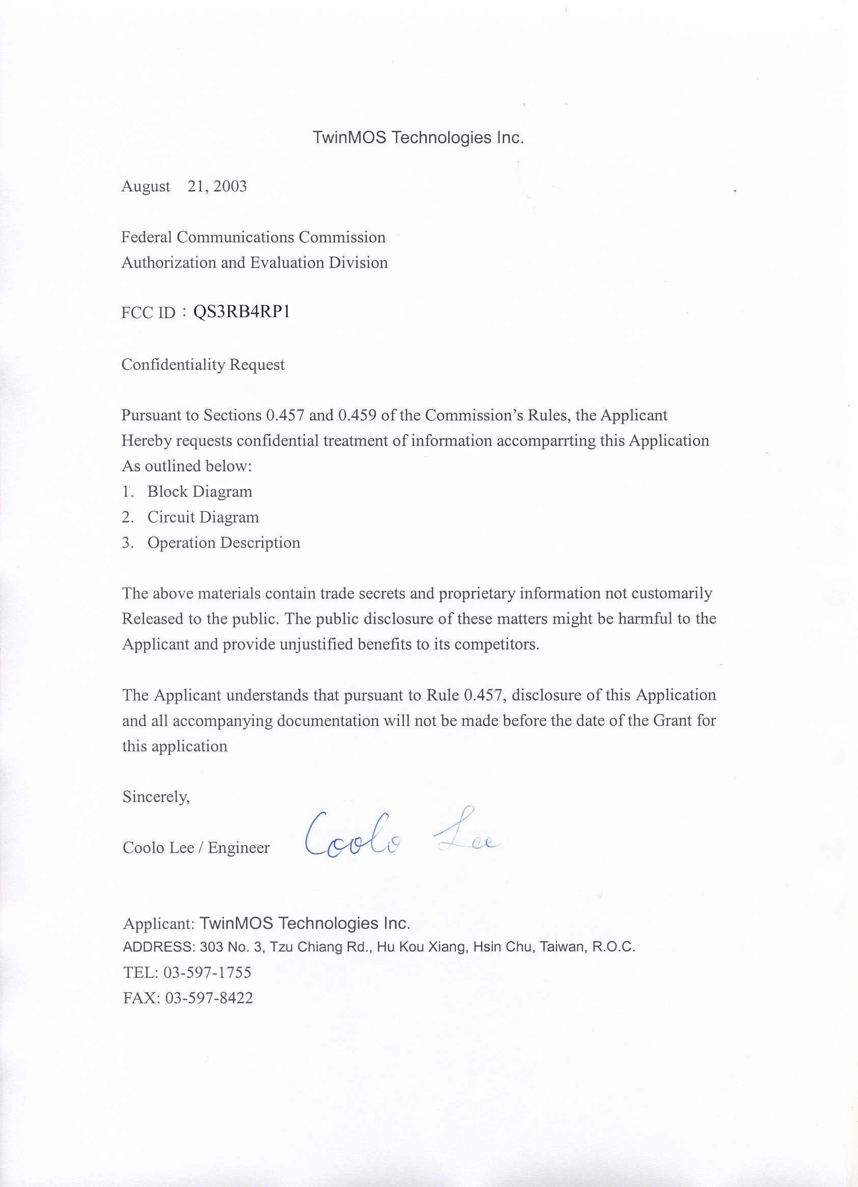
FEDERAL COMMUNICATIONS COMMISSION Authorization and Evaluation Division 7435 Oakland Mills Road Columbia, MD 21046 U.S.A. To whom it may concern: We, hereby, declare that we do not provide any user manual, control or software to allow user to operate outside the USA frequency band for the product, FCC ID: QS3RB4RP1. Date: Aug. 28, 2003
External Photos
FCC ID: QS3RB4RP1 Number1 FRONT SIDE OF EUT FCC ID: QS3RB4RP1 Number2 REAR SIDE OF EUT FCC ID: QS3RB4RP1 Number3 CLOSER LOOK OF REAR INTERFACE PORT FCC ID: QS3RB4RP1 Number4 FRONT SIDE OF ADAPTER FCC ID: QS3RB4RP1 Number5 REAR SIDE OF ADAPTER FCC ID: QS3RB4RP1 Number6 FRONT SIDE OF ADAPTER FCC ID: QS3RB4RP1 Number7 RS-232 CABLE
ID Label/Location Info
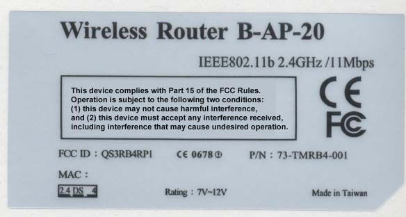
FCC ID: QS3RB4RP1 Label Location
Internal Photos
FCC ID: QS3RB4RP1 Number 1 MECHANICAL CONSTRUCTION FCC ID: QS3RB4RP1 Number 2 MECHANICAL CONSTRUCTION FCC ID: QS3RB4RP1 Number 3 MECHANICAL CONSTRUCTION FCC ID: QS3RB4RP1 Number 4 FRONT SIDE OF MAIN BOARD FCC ID: QS3RB4RP1 Number 5 REAR SIDE OF MAIN BOARD
Test Report
FCC TEST REPORT Report No. : F373108 SPORTON International Inc. FCC ID : QS3RB4RP1 TEL : 886-2-2696-2468 Page No. : 1 of 8 FAX : 886-2-2696-2255 Issued Date : Aug. 15, 2003 1.1. 6dB Bandwidth Plot1(Channel 01) FCC TEST REPORT Report No. : F373108 SPORTON International Inc. FCC ID : QS3RB4RP1 TEL : 886-2-2696-2468 Page No. : 2 of 8 FAX : 886-2-2696-2255 Issued Date : Aug. 15, 2003 Plot2(Channel 06) FCC TEST REPORT Report No. : F373108 SPORTON International Inc. FCC ID : QS3RB4RP1 TEL : 886-2-2696-2468 Page No. : 3 of 8 FAX : 886-2-2696-2255 Issued Date : Aug. 15, 2003 Plot3(Channel 11) FCC TEST REPORT Report No. : F373108 SPORTON International Inc. FCC ID : QS3RB4RP1 TEL : 886-2-2696-2468 Page No. : 4 of 8 FAX : 886-2-2696-2255 Issued Date : Aug. 15, 2003 1.2. Power Spectral Density Plot1(Channel 01): FCC TEST REPORT Report No. : F373108 SPORTON International Inc. FCC ID : QS3RB4RP1 TEL : 886-2-2696-2468 Page No. : 5 of 8 FAX : 886-2-2696-2255 Issued Date : Aug. 15, 2003 Plot2(Channel 06): FCC TEST REPORT Report No. : F373108 SPORTON International Inc. FCC ID : QS3RB4RP1 TEL : 886-2-2696-2468 Page No. : 6 of 8 FAX : 886-2-2696-2255 Issued Date : Aug. 15, 2003 Plot3(Channel 11): FCC TEST REPORT Report No. : F373108 SPORTON International Inc. FCC ID : QS3RB4RP1 TEL : 886-2-2696-2468 Page No. : 7 of 8 FAX : 886-2-2696-2255 Issued Date : Aug. 15, 2003 1.3. Band Edges Measurement Plot1 (Channel 01) FCC TEST REPORT Report No. : F373108 SPORTON International Inc. FCC ID : QS3RB4RP1 TEL : 886-2-2696-2468 Page No. : 8 of 8 FAX : 886-2-2696-2255 Issued Date : Aug. 15, 2003 Plot2 (Channel 11)
Test Report
FCC TEST REPORT Report No. : F373108 SPORTON International Inc. TEL : 886-2-2696-2468 FAX : 886-2-2696-2255 FCC TEST REPORT for 47 CFR, Part 15, Subpart C Equipment : Wireless Router Model No. : 73-TMRB4-001 FCC ID : QS3RB4RP1 Filing Type : Certification Applicant : TwinMOS Technologies Inc. 303 No. 3, Tzu Chiang Rd., Hu Kou Xiang, Hsin Chu, Taiwan, R.O.C. The test result refers exclusively to the test presented test model / sample. Without written approval of SPORTON International Inc., the test report shall not be reproduced except in full. Certificate or Test Report must not be used by the applicant to claim the product in this test report endorsement by NVLAP or any agency of U.S. government. SPORTON International Inc. 6F, No.106, Sec. 1, Hsin Tai Wu Rd., Hsi Chih, Taipei Hsien, Taiwan, R.O.C. FCC TEST REPORT Report No. : F373108 SPORTON International Inc. FCC ID : QS3RB4RP1 TEL : 886-2-2696-2468 Page No. : i FAX : 886-2-2696-2255 Issued Date : Aug. 15, 2003 Table of Contents History of this test report..................................................................................................................ii CERTIFICATE OF COMPLIANCE........................................................................................................................1 1. General Description of Equipment under Test.............................................................................................2 1.1. Applicant..........................................................................................................................................................................................2 1.2. Manufacturer ...................................................................................................................................................................................2 1.3. Basic Description of Equipment under Test ....................................................................................................................................2 1.4. Feature of Equipment under Test ...................................................................................................................................................2 2. Test Configuration of Equipment under Test ...............................................................................................3 2.1. Test Manner ....................................................................................................................................................................................3 2.2. Description of Test System .............................................................................................................................................................3 2.3. Connection Diagram of Test System ..............................................................................................................................................5 3. Test Software ...................................................................................................................................................6 4. General Information of Test............................................................................................................................7 4.1. Test Voltage ....................................................................................................................................................................................7 4.2. Standard for Methods of Measurement...........................................................................................................................................7 4.3. Test in Compliance with ..................................................................................................................................................................7 4.4. Frequency Range Investigated .......................................................................................................................................................7 4.5. Test Distance ..................................................................................................................................................................................7 5. Report of Measurements and Examinations ................................................................................................8 5.1. List of Measurements and Examinations ........................................................................................................................................8 5.2. 6dB Bandwidth ................................................................................................................................................................................9 5.3. Peak Output Power .......................................................................................................................................................................10 5.4. Power Spectral Density .................................................................................................................................................................11 5.5. Test of Conducted Emission .........................................................................................................................................................12 5.6. Test of Radiated Emission ............................................................................................................................................................19 5.7. Band Edges Measurement............................................................................................................................................................34 5.8. Antenna Requirements .................................................................................................................................................................35 5.9. RF Exposure ..............................................................................................................................…
Text truncated - open the document above for the full version.
Test Setup Photos
FCC TEST REPORT Report No. : F373108 SPORTON International Inc. FCC ID : QS3RB4RP1 TEL : 886-2-2696-2468 Page No. : 1 of 3 FAX : 886-2-2696-2255 Issued Date : Aug. 15, 2003 1.1. Photographs of Conducted Emission Test Configuration The photographs show the configuration that generates the maximum emission. FRONT VIEW REAR VIEW FCC TEST REPORT Report No. : F373108 SPORTON International Inc. FCC ID : QS3RB4RP1 TEL : 886-2-2696-2468 Page No. : 2 of 3 FAX : 886-2-2696-2255 Issued Date : Aug. 15, 2003 SIDE VIEW FCC TEST REPORT Report No. : F373108 SPORTON International Inc. FCC ID : QS3RB4RP1 TEL : 886-2-2696-2468 Page No. : 3 of 3 FAX : 886-2-2696-2255 Issued Date : Aug. 15, 2003 1.2. Photographs of Radiated Emission Test Configuration The photographs show the configuration that generates the maximum emission. FRONT VIEW REAR VIEW
Contact Information
Applicant
Sam Hsu(Manager)
Test Firm
Sporton International Inc.Kathy Lin
Technical Specifications
| # | Rule Parts | Frequency Range | Power Output |
|---|---|---|---|
| 1 | 15C | 2.41 GHz - 2.46 GHz | 28.57 mW |
Other Applications from TwinMOS Technologies Inc.

QS3-BTTA01
Oct 01, 2006Bluetooth 2.1ch Audio System for iPod
Equipment Class
DSS - Part 15 Spread Spectrum Transmitter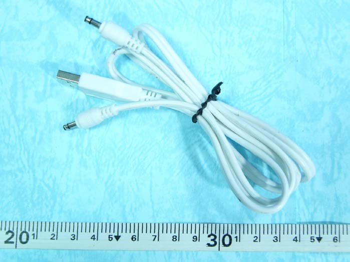
QS3BTT102
Feb 22, 2006Bluetooth Aduio Receiver
Equipment Class
DSS - Part 15 Spread Spectrum Transmitter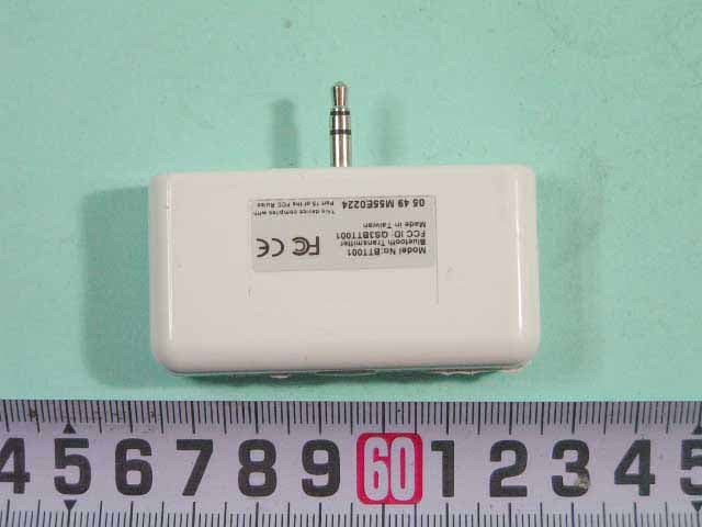
QS3BTT001
Dec 29, 2005Bluetooth Audio Transmitter
Equipment Class
DSS - Part 15 Spread Spectrum Transmitter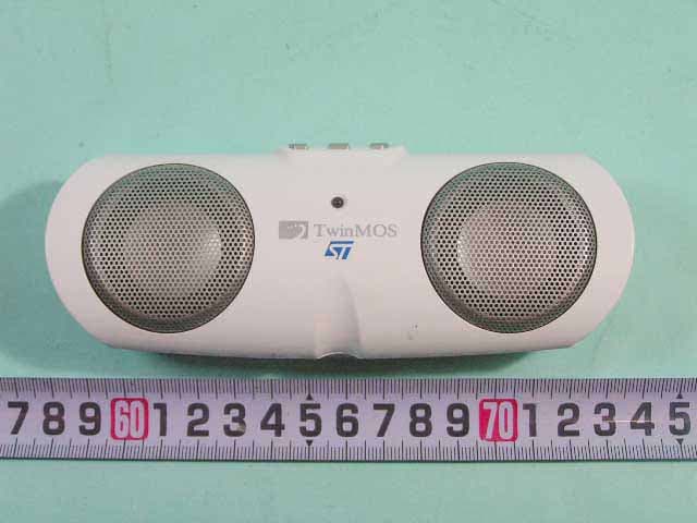
QS3BTT101
Dec 28, 2005Bluetooth Portable Speaker
Equipment Class
DSS - Part 15 Spread Spectrum Transmitter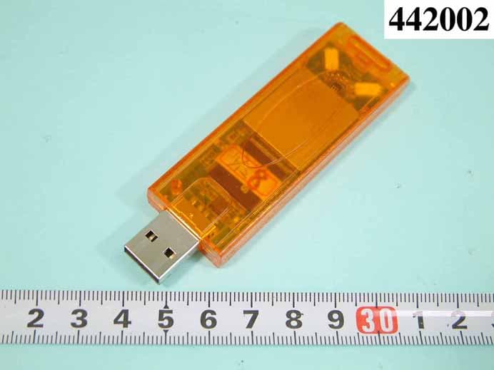
QS3WGSZR1
Oct 31, 2004USB STICK WLAN CARD
Equipment Class
DTS - Digital Transmission System