QS3WGBPR1802.11 b/g Mini-PCI Card
TwinMOS Technologies Inc.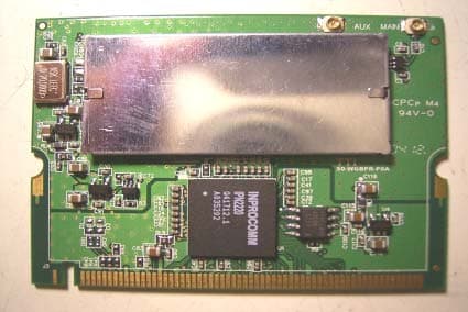
Click to zoom
Application Details
- Equipment Class
- DTS - Digital Transmission System
- Date of Grant
- Apr 18, 2004
- Application Purpose
- Original Equipment
- Date of Application
- Apr 18, 2004
- Equipment Note
- 802.11 b/g Mini-PCI Card
- Frequency Range
- 2412.00000000 - 2462.00000000
- Company
- TwinMOS Technologies Inc.
- Country
- Taiwan
Documents & Files
Document Text
Text extracted from the exhibit documents filed with the FCC. Open a document above to read the original.
Users Manual
802.11b/g Series Wireless LAN Adapter (For OEMs use only) User’s Manual G101 Series WLAN Card Page 1 Contents PACKAGE CONTENTS...................................................................................2 INTRODUCTION...............................................................................................3 G101 WIRELESS NETWORK SCENARIOS..........................................4 HARDWARE INSTALLATION....................................................................7 SOFTWARE INSTALLATION FOR WINDOWS (XP/2000/98SE).....................10 CONFIGURATION UTILITY.....................................................................40 SOFTWARE INSTALLATION FOR LINUX...................................................56 TROUBLESHOOTING...................................................................................59 TECHNICAL SPECIFICATIONS.....................................................................60 FCC CAUTION......................................................................................61 G101 Series WLAN Card Page 2 PACKAGE CONTENTS Unpack your G101 WLAN adapterkit and verify that all items are present. zG101 MiniPCI Wireless LAN Adapter zUser’s Manual (on CD) zDriver (on CD) If any of the items described appear to be damaged or missing, please contact TwinMOS G101 Series WLAN Card Page 3 INTRODUCTION TheG101 WLAN adapter is a wireless network client that complies with the IEEE 802.11b/g standard on wireless LANs. The IEEE 802.11b/g standards compliance means this adaptergives you the flexibility to connect it to any 802.11b/g network. The IEEE 802.11b/g Ethernet standard allows you to have network connection speed of up to 11Mbps, dependent upon the distance between wirelessadapters, the configuration of your working environment, or the capabilities or limitations ofthe applicable network systems. ThisG101WLAN Adapter supports following WLAN features zAutomatic transmit data rate select mechanism in the transmit range of 1, 2, 5.5, 6, 9, 12, 18, 24, 36, 48 and 54 Mbps. zCenter frequency channel selection (2.4 GHz) zRoaming over multiple channels. zSupports MiniPCI interface for G101 zSupports power save mode zSupports WPA zSupports 64/128/152-bit Wired Equivalent Privacy (WEP), TKIP, AES data encryption. ThisG101comes with software drivers for the most popular MicrosoftWindows operating systems and can be integrated into a larger network, running Windows XP, Windows 2000, Windows ME, or Windows 98 in either Ad-Hoc mode or infrastructure mode. This manual provides a quick introduction to wireless technology and itsapplication as it relates to networking. Take a moment to read through this manual and familiarize you with wireless technology. G101 Series WLAN Card Page 4 G101 WIRELESS NETWORK SCENARIOS TheG101WLAN adapter offers to: zConnect an Ad-Hoc workgroup of wireless computing devices (see Figure 1-1 on page 6). zConnect to a Small Office/Home Office (SOHO) network that includes a Residential Gateway (RG) access point (see Figure 1-2 on page 7). zConnect to a Local Area Network (LAN) Infrastructure that includes Access Points, or other IEEE 802.11 compliant LAN systems (see Figure 1-3 and Figure 1-4). zExpand the capabilities of an Access Point, supporting wireless devices that have been equipped with G101. Ad-Hoc Workgroup The Ad-Hoc workgroup configuration facilitates to quickly set up a small wireless workgroup, where the workgroup participants can exchange files using features like “Files and Printer Sharing” as supported by Microsoft Networking. Figure 1-1 A d-Hoc Wireless Workgroup This option offers to setup a temporary or ad-hoc network inenvironments where no access points are available (for example, in SmallOffice/Home Office (SOHO) environments). As long as the stations are within range of one another, this is the easiest and least expensive way to set up a wireless network. G101 Series WLAN Card Page 5 Home Networking With theG101WLAN adapter,wireless access to the Internet or other computing devices is fingertips. What needs to do is toconnect the wireless devices to anexternal cable, an xDSL or a ISDN modem and you are ready to zShare files and printers, and zAccess the Internet Figure 1-2 Connect to a Residential Gateway (RG) Enterprise Networking With the 11 Mbps Wireless LAN access point, one can connect to a corporate Local Area Network (LAN) infrastructure to have wireless access to all network facilities. LAN Infrastructures may either be: zStand-alone wireless LANs (Figure 1-3). zWireless network infrastructures connected to an existing Ethernet network (Figure 1-4). Figure 1-3Stand Alone Wireless LAN xDSL G101 Series WLAN Card Page 6 Figure 1-4LAN Infrastructure It’s Easy TheG101 functions like any standard wired Ethernet card, but G101 does not need any wires! Where an Ethernet card requires a cable connection to a hub and/or patch panel, the cable physically ties user down to the location of the wired connection. G101offers connection to a Local Area Network (LAN) system from anywhere within the wireless coverage area. Expanding or re-designing user network is easy: Add or relocate access point, power-up your (new) wirelessdevice, and the job is done! Unlike Ethernet, G101 will allow you to roam throughout the network while remaining connected to the LAN. Note The G101 wireless adapter is a radio product. Refer to the flyer ”Information to the User” for regulatory information that may apply in your country. G101 Series WLAN Card Page 7 HARDWARE INSTALLATION Product View Golden Finger Antenna connectors, J1 (Main) and J2 (Aux) J1J2 G101 Series WLAN Card Page 8 Installing the G101 The following diagrams provide the basic installation for the G101, including how to install into and remove from the MiniPCI slot the MiniPCI card. 1. Locate the Mini PCI slot. 2. Place the G101 over the MiniPCI slot (at an angle of 30 degrees). Then, gently insert it intothe slot until the golden finger of the card gets fully inserted. 3. Press down …
Text truncated - open the document above for the full version.
Users Manual
G101 Series WLAN Card Page 30 3. Licence Agreement ,Please choice “I accept the terms in the license agreement ” and click "Next" to continue. 4.Click "Install" button to continue. G101 Series WLAN Card Page 31 zThe driver and utility are Installing. zClick Finish button to complete install procedure. G101 Series WLAN Card Page 32 5.Insert the G101 WLAN adapter into the MiniPCI slot, the system will automatically find the device and search for its software then the InstallShield Wizard finished installation and the system tray icon is loaded in the taskbar (see illustration below). Note: Please turn-off computer before user insert G101. zFound New Hardware and Installing. zComplete device install. G101 Series WLAN Card Page 33 6.Please click “Start-> programs -> Inprocomm->IPN2220 WLAN Configuration Utility”. zThe WLAN icon willappear. 7.The “WLAN Configuration Utility” screen will appear. G101 Series WLAN Card Page 34 For Windows 98SE Install the Driver and Utility 1. Insert the CD into the CD-ROM device and execute the "setup.exe "programfor G101 series to select. 2.The InstallShield Wizard box will appear, click "Next" to continue. 3. Licence Agreement appears. Please choice “I accept the terms in the license agreement” and click G101 Series WLAN Card Page 35 "Next" to continue. 4. Click "Install" button to continue. G101 Series WLAN Card Page 36 zThe driver and utility are Installing. zClick Finish button to complete install procedure. 5. After running the driver package, it will be requested restart Win98 OS. G101 Series WLAN Card Page 37 6. Insert the G101 WLAN adapter into the MiniPCI slot. The system will automatically find the device and search for its software then the InstallShield Wizard finished installation and the system tray icon is loaded in the taskbar (see illustration below). Note: Please turn off the power before you insert G101. zNew Hardware Found 7. Please insert the disk labeled "Windows 98 Second Edition CD-ROM." 8. To choose Windows 98SE installing folder G101 Series WLAN Card Page 38 9. Copying Files 10. Please click “Start-> programs -> Inprocomm->IPN2220 WLAN Configuration Utility”. G101 Series WLAN Card Page 39 zThe WLAN icon will appear. 11. The “WLAN Configuration Utility” screen will appear. G101 Series WLAN Card Page 40 CONFIGURATION UTILITY Note: The followingConfiguration Utility was operated under Windows 2000. (Procedures will be the same for Windows 98SE/XP) G101uses the Configuration Utility as the management software. The utility provides an easy interface to change any settings related to the wireless adapter. When the computer is started, the Configuration Utility starts automatically and the system tray icon is loaded in the toolbar (see illustration belo w.) Clicking on the utility icon will start the Configuration Utility. Double-click on the icon shown above. The screen below will appear. G101 Series WLAN Card Page 41 Right -click on the icon shown below. The function of utility icon will appear. Exit Clicking on the “Exit ” Button will leave the Configuration Utility. Connect From “Profiles list” to select one of all profiles name (G-AP-10) to connect. Radio On –Turn Radio on. Off –Turn Radio off. G101 Series WLAN Card Page 42 Status Tab Signal Strength This bar shows the signal strength level. The higher percentage shown in the bar, the more radio signal been received by theadapter. This indicator helps to find the proper position of thewireless device for quality network operation. Link Quality This bar indicates the quality of the link. The higher the percentage, the better the quality. G101 Series WLAN Card Page 43 Configuration Table Click the “Configuration Button” toget into the Configuration Table, as shown below. G101 Series WLAN Card Page 44 General Tab Any of the fields shown below can be changed without re-starting the OS. Profile name A profile is a named set of operating parameters for theG101WLAN adapter to display the available profiles for theG101 WLAN adapter. Network Type TheG101 WLAN adapter can operate in one of two modes, which are specified in the Mode field of the Configuration menu. Clicking the down arrow at the right of the Mode field displays the available modes. Ad-Hoc Station- This is the 802.11b/g Ad-Hoc mode of operation. In “Ad-Hoc” mode, only one wireless “cell ” is supported for each different NETWORK NAME. All communication is done from client to client without the use of an Access Point. “Peer-to-Peer” networking uses the same NETWORK NAME for the wireless adapters in establishing the network connection. When “Ad-Hoc ” mode is selected, the utility will provide a selection for setting the channel. Infrastructure Station- This mode of operation requires the presence of an 802.11b/g Infrastructure. All communication is done through the Infrastructure, which relays packets to other wireless clients as well as to nodes on a wired Ethernet network. G101 Series WLAN Card Page 45 SSID The name of the wireless network. This name cannot be longer than 32 characters. The default value is “any”, which will automatically scan and connect the best performance Access point nearby. User may specify a SSID for the adapter and then only the device with the same SSID can interconnect to the adapter. Channel When communicating in Ad-Hoc mode, User must specify a channel on which communications will take place. This field is grayed in infrastructure mode because the Access Point automatically selects the channel. Desired Rate The Transmit Rate field specifies the rate at which the radio in user’sG101 WLAN adapter transmits and receives data. User can set this to the following fixed rates: 1 Mbps; 2Mbps; 5.5 Mbps; 6 Mbps; 9 Mbps; 12 Mbps; 18 Mbps; 24 Mbps; 36 Mbps; 48 Mbps or 54 Mbps. Automatic -When it is enabled, the device will choose the most suitabletransmission rate automatically. Apply Click “Apply” button to save and implement the new settings. G101 Series WLAN Card Page 46 Encryption Tab To allows to enhancing the …
Text truncated - open the document above for the full version.
Cover Letter(s)
Mike Kuo From: [email protected] Sent: April16 2004 Friday 7:32 AM To: Mike Kuo Cc: [email protected]; [email protected]; [email protected]; [email protected] Subject: RE: FW: TwinMOS Technologies Inc. , FCC ID:QS3WGBPR1, AN04T3827 4/19/2004 Hi Mike, Sorry. Here is the revised manual in the PDF format. Best Rgds, WK ----- wklo/ccsemc 2004/04/16 09:26 PM ----- Hi Mike, Thank you for your advice. Here is the re-revised manual and brief description of the revise. Reply to Question #5 has not fully addressed the question. In my question #5, I asked the OEM manual to provide " How to " instruction to install the mini-PCI and dipole antenna into the final system. As indicated in the revised user manual, this device will be installed in desktop computer. Since desktop computer does not equip with mini-PCI slot and no place to mount external dipole antenna. Please provide the ANTENNA INSTALLATION instruction and HOW TO install mini-PCI card in desktop computer. Response: The module intends to be installed in a MiniPCI slot by an OEM vendor. Hence, suitable wordings are added to stress this point and wording impling a computer system is removed. In addition, on page 61 of user manual, it indicates " This device is approved for OEM installation with specified antennas as listed in this Manual." However, there is no SPECIFIED antenna is listed in the user manual. Please explain. Responce: The sentence on Page 61 you referred to is re-edited. Once again, in page 59 of user manual under " Troubleshooting ", the language is written in such way that this device is actually installed by the end user which does not agree with OEM installation only statement. Response: The style of the writing on Page 59 is revised. Besides, the whole contents are also revised to make it more specific as an OEM installation guide. wklo 2004/04/16 04:44 PM Mike Kuo <[email protected]> ting/ccsemc@ccsemc, harris/ccsemc@ccsemc, skang/ccsemc@ccsemc, tomchuang/ccsemc@ccsemc Thank you again. Please give the grant at your earliest convenience if there is no further issues. Best Rgds, WK Hi Ting: Reply to Question #5 has not fully addressed the question. In my question #5, I asked the OEM manual to provide " How to " instruction to install the mini- PCI and dipole antenna into the final system. As indicated in the revised user manual, this device will be installed in desktop computer. Since desktop computer does not equip with mini-PCI slot and no place to mount external dipole antenna. Please provide the ANTENNA INSTALLATION instruction and HOW TO install mini-PCI card in desktop computer. In addition, on page 61 of user manual, it indicates " This device is approved for OEM installation with specified antennas as listed in this Manual." However, there is no SPECIFIED antenna is listed in the user manual. Please explain. Once again, in page 59 of user manual under " Troubleshooting ", the language is written in such way that this device is actually installed by the end user which does not agree with OEM installation only statement. Best Regards Mike Kuo -----Original Message----- From: [email protected] [mailto:[email protected]] Sent: Wednesday, April 14, 2004 7:09 PM To: Mike Kuo Cc: [email protected]; [email protected] Subject: FW: TwinMOS Technologies Inc. , FCC ID:QS3WGBPR1, AN04T3827 Hi Mike, Attached is the revised manual to answer your Question 5 & 6. The following give description of the answer. Question #5:The revised user manual / OEM installation instruction did not address the question #1. As I indicated in my question #1:, only dipole antenna is submitted in this application. How is this dipole antenna will be installed in the notebook computer or in the desktop computer ? Please provide required antenna installation location and method to install this dipole antenna . In the revised user manual / OEM installation instruction, only has picture to show how to install mini-PCI card. Ans 5: The manual is re-edited to reflect the product's application in the intended environment. And, the wording of notebook is deleted. Mike Kuo <[email protected]> 2004/04/15 03:27 PM "'[email protected]'" <[email protected]>, Mike Kuo <[email protected]> [email protected], Shirley Kang- Taiwan <[email protected]> 4/19/2004 Question #6: Your reply to Question #2 does not match with user manual / OEM installation instruction. Page 3 of user manual indicates "If any of the items described appear to be damaged or missing, please contact your reseller. ". Many places in the user manual still provide instruction in how to install the mini-PCI card by the end user. Ans 6: The targeted audience for the product's manual is the OEM vendor, as described more specific in this revised manual. The wording of "reseller" is changed to that of "TwinMos." I hope this would conclude your review. This customer is hard earned from our competitor and we have promised a competitive schedule. Please give the grant as sson as possible if there is no further issue. Thank you very for your assistance. Best Rgds, Ting Hi Ting: Question #5:The revised user manual / OEM installation instruction did not address the question #1. As I indicated in my question #1:, only dipole antenna is submitted in this application. How is this dipole antenna will be installed in the notebook computer or in the desktop computer ? Please provide required antenna installation location and method to install this dipole antenna . In the revised user manual / OEM installation instruction, only has picture to show how to install mini-PCI card. Question #6: Your reply to Question #2 does not match with user manual / OEM installation instruction. Page 3 of user manual indicates "If any of the items described appear to be damaged or missing, please contact your reseller. ". Many places in the user manual still provide instruction in how to install the mini-PCI card by the end user. Best Regards Mike Kuo -----Original Message----- From: Sent: None Subject: Hi Mike, Here are ou…
Text truncated - open the document above for the full version.
External Photos
Compliance Certification Services Inc. Report No: B40326601 Date of Issue: March 30, 2004 Page 1 of 2 EXTERNAL PHOTO
ID Label/Location Info
Size: 2.8W x 1.2H(導R角) Mini-PCI Wireless LAN Card FCC ID:QS3WGBPR1 Model:G101 Made in Taiwan
Internal Photos
Compliance Certification Services Inc. Report No: B40326601 Date of Issue: March 30, 2004 Page 2 INTERNAL PHOTO
Parts List/Tune Up Info
Antenna Specifications: Product Name: 2.4GHz Dipole with 100 mm 1.13Cable ACON P/N: ADA3I-3K52205 Electrical performance: Frequency: 2.4 ~2.5GHz Return Loss: < -10dB @ 50 ohms VSWR: < 2.0 @ 50 ohms Antenna Gain: 2.0dBi (Omni-directional) Polarization: Linear Vertical Mechanical performance: Material: TPU Color: Black Connector: MHF Connector Temperature: -20 ~ +60 Dimension: 9.0*104.6mm Number 60 H-PLAN 2400 2450 2500 E-PLAN 2400 2450 2500
Test Report
Compliance Certification Services Inc. Report No: B40326601-RP FCC ID: QS3WGBPR1 Date of Issue: March 30, 2004 Note: This report shall not be reproduced except in full, without the written approval of Compliance Certification Services Inc. This document may be altered or revised by Compliance Certification Services Inc. personnel only, and shall be noted in the revision section of the document. Page 1 of 69 FCC 47 CFR PART 15 SUBPART C TEST REPORT For TwinMOS Technologies Inc. Mini PCI card Model: G101 Tr a d e Na me : Tw i nMO S Prepared for TwinMOS Technologies Inc. No. 3, Tzu Chiang Rd., Hu Kou Xiang, Hsien Chu, Taiwan, R.O.C. Prepared by Compliance Certification Services Inc. No. 81-1, Lane 210, Bade Rd. 2, Luchu Hsiang, Taoyuan Hsien, (338) Taiwan, R.O.C. TEL: 886-3-324-0332 FAX: 886-3-324-5235 Compliance Certification Services Inc. Report No: B40326601-RP FCC ID: QS3WGBPR1 Date of Issue: March 30, 2004 Page 2 TABLE OF CONTENTS 1. TEST RESULT CERTIFICATION............................................................................................. 3 2. EUT DESCRIPTION .................................................................................................................... 4 3. TEST METHODOLOGY ............................................................................................................. 5 3.1 EUT CONFIGURATION...................................................................................................................5 3.2 EUT EXERCISE...............................................................................................................................5 3.3 GENERAL TEST PROCEDURES........................................................................................................5 3.4 FCC PART 15.205 RESTRICTED BANDS OF OPERATIONS...................................................6 3.5 DESCRIPTION OF TEST MODES......................................................................................................6 4. INSTRUMENT CALIBRATION................................................................................................. 7 5. FACILITIES AND ACCREDITATIONS ................................................................................... 8 5.1 FACILITIES ....................................................................................................................................8 5.2 EQUIPMENT...................................................................................................................................8 5.3 LABORATORY ACCREDITATIONS AND LISTING.............................................................................8 5.4 TABLE OF ACCREDITATIONS AND LISTINGS..................................................................................9 6. SETUP OF EQUIPMENT UNDER TEST ................................................................................ 10 6.1 SETUP CONFIGURATION OF EUT..................................................................................................10 6.2 SUPPORT EQUIPMENT ..........................................................................................................10 7. FCC PART 15.247 REQUIREMENTS...................................................................................... 11 7.1 6DB BANDWIDTH........................................................................................................................11 7.2 PEAK POWER...............................................................................................................................17 7.3 BAND EDGES MEASUREMENT ...........................................................................................23 7.4 PEAK POWER SPECTRAL DENSITY...............................................................................................33 7.5 RADIO FREQUENCY EXPOSURE...................................................................................................39 7.6 SPURIOUS EMISSIONS ...........................................................................................................42 7.7 POWERLINE CONDUCTED EMISSIONS..........................................................................................64 Compliance Certification Services Inc. Report No: B40326601-RP FCC ID: QS3WGBPR1 Date of Issue: March 30, 2004 Page 4 2. EUT DESCRIPTION Product Mini PCI card Trade Name TwinMOS Model Number G101 Model Discrepancy N/A Power Supply Powered from host device Frequency Range 2412 ~ 2462 MHz Transmit Power (mean EIRP) 802.11b mode: 19.69 dBm 802.11g mode: 18.73 dBm Modulation Technique 802.11b: DSSS (CCK; DQPSK; DBPSK) 802.11g: OFDM Transmit Data Rate 802.11b: 11Mbps(CCK) with fall back rates of 5.5, 2, and 1Mbps 802.11g: 54Mbps with fall back rates of 48/36/24/18/12/9 Mbps (OFDM) Number of Channels 11 Channels Antenna Specification Diople Antennas Ant Gain: 2 dBi (max) Temperature Range 0 ~ + 55°C Note: This submittal(s) (test report) is intended for FCC ID: QS3WGBPR1 filing to comply with Section 15.247 of the FCC Part 15, Subpart C Rules. Compliance Certification Services Inc. Report No: B40326601-RP FCC ID: QS3WGBPR1 Date of Issue: March 30, 2004 Page 5 3. TEST METHODOLOGY The tests documented in this report were performed in accordance with ANSI C63.4 and FCC CFR 47 2.1046, 2.1047, 2.1049, 2.1051, 2.1053, 2.1055, 2.1057, and 15.247. 3.1 EUT CONFIGURATION The EUT configuration for testing is installed on RF field strength measurement to meet the Commissions requirement and operating in a manner that intends to maximize its emission characteristics in a continuous normal application. 3.2 EUT EXERCISE The EUT (Mini PCI card) was operated in the engineering mode to fix the TX frequency that was for the purpose of the measurements. According to its specifications, the EUT must comply with the requirements of the Section 15.247 under the FCC Rules Part 15 Subpart C. 3.3 GENERAL TEST PROCEDURES Conducted Emissions The EUT is placed on the turntable, which is 0.8 m above ground …
Text truncated - open the document above for the full version.
Test Setup Photos
Compliance Certification Services Inc. Report No: B40326601-RP FCC ID: QS3WGBPR1 Date of Issue: March 30, 2004 Page 68 APPENDIX 1 PHOTOGRPHS OF TEST SETUP Radiated Emission Set up Photos Compliance Certification Services Inc. Report No: B40326601-RP FCC ID: QS3WGBPR1 Date of Issue: March 30, 2004 Page 69 Conducted Emission Set Up Photos
Contact Information
Applicant
Sam Hsu(Manager)
Test Firm
Compliance Certification Services Inc.Tony Houng
Technical Specifications
| # | Rule Parts | Frequency Range | Power Output |
|---|---|---|---|
| 1 | 15C | 2.41 GHz - 2.46 GHz | 93.00 mW |
Other Applications from TwinMOS Technologies Inc.

QS3-BTTA01
Oct 01, 2006Bluetooth 2.1ch Audio System for iPod
Equipment Class
DSS - Part 15 Spread Spectrum Transmitter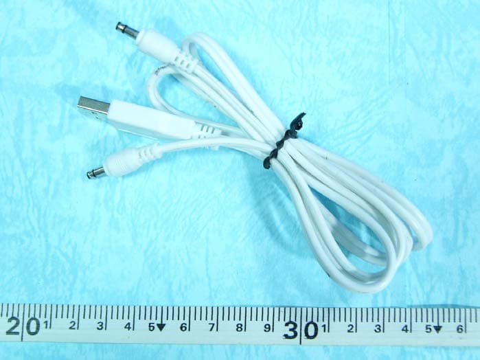
QS3BTT102
Feb 22, 2006Bluetooth Aduio Receiver
Equipment Class
DSS - Part 15 Spread Spectrum Transmitter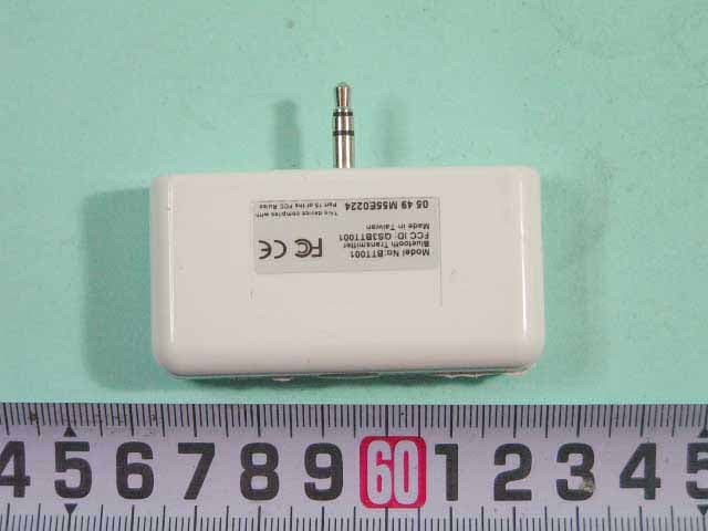
QS3BTT001
Dec 29, 2005Bluetooth Audio Transmitter
Equipment Class
DSS - Part 15 Spread Spectrum Transmitter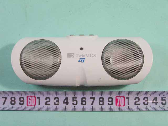
QS3BTT101
Dec 28, 2005Bluetooth Portable Speaker
Equipment Class
DSS - Part 15 Spread Spectrum Transmitter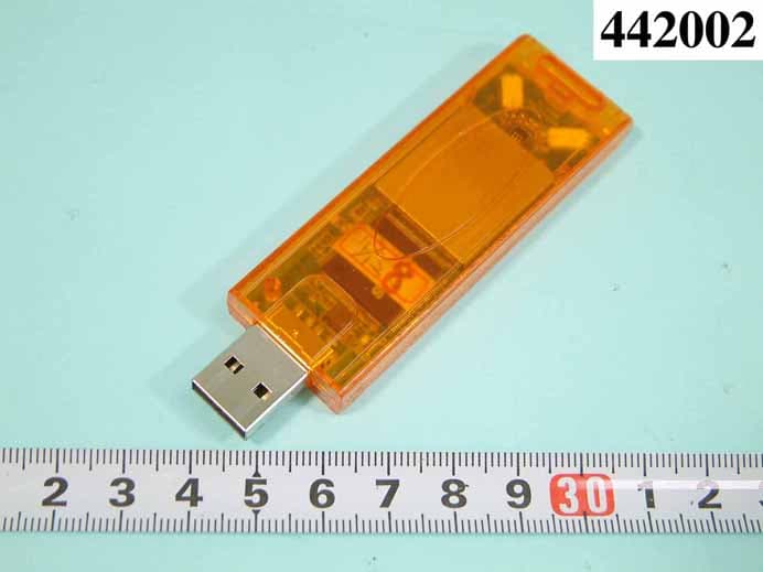
QS3WGSZR1
Oct 31, 2004USB STICK WLAN CARD
Equipment Class
DTS - Digital Transmission System