QSCWAYSIDETransportation Control System
Siemens Transportation Systems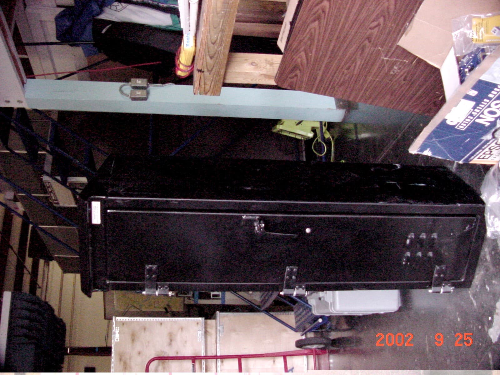
Click to zoom
Application Details
- Equipment Class
- DSS - Part 15 Spread Spectrum Transmitter
- Date of Grant
- Feb 11, 2003
- Application Purpose
- Original Equipment
- Date of Application
- Dec 17, 2002
- Equipment Note
- Transportation Control System
- Frequency Range
- 2408.00000000 - 2474.00000000
- Country
- France
Documents & Files
Document Text
Text extracted from the exhibit documents filed with the FCC. Open a document above to read the original.
Users Manual
Siemens Transportation Systems exclusive property Siemens Transportation Systems Note interne / Memorandum Emetteur / From Destinataire (s) / To S.AZOUIGUI Dir. ou Sce. : Department : Centre : P. Inglis, G. Sulmont Date : 21/08/02 Réf. : Mémo : Copie (s) / Copy(ies) OBJET / SUBJECT : STS Train Radio User Manual - FCC Test Configuration DRAFT VERSION 1. CONFIGURATION The test configuration is : one WRE, not redundant (unlike NYCT config). The CIDO board (FO Wayside Radio Network) is not enclosed. one CRE, not redundant (as NYCT config). The CIDRE board (Train Radio Network) is not enclosed. 1.1. WRE – Wayside Radio Equipment 1.1.1. WRE characteristics The WRE is a cardfile which complies with the IEC 60297-3 standard and has the following characteristics : Height : 266.7 mm = 10.5" Width : 238.8mm = 9.4" Depth : <290mm/9.4" Weight : <15Kg/30Lbs Réf. : Mémo : Date : 21/08/02 - 2 - Siemens Transportation Systems exclusive property 1.1.2. Power supply of the WRE Nominal : 24 VDC Range : 16 VDC to 36 VDC Maximum Power : 80 W 1.1.3. RF outputs of the WRE Two outputs respectively identified as RFA1 and RFA2 for the WRU-A (WRU-B is not used). 50 Ohm coaxial cable terminated by a N male type plug. 1.1.4. View of the WRE – Test configuration Figure 1 : The WRE 1.2. CRE – Carborne Radio Equipment 1.2.1. CRE characteristics The CRE is a cardfile which complies with the IEC 60297-3 standard and has the following characteristics: Height : 133.35mm = 5.25" Width : 482.6mm=19" Depth : <320mm/12.6" Weight : <10Kg/20Lbs 1.2.2. Power supply of the CRE Nominal : 37.5 VDC Range : 24 VDC to 44 VDC Maximum Power : 80 W Réf. : Mémo : Date : 21/08/02 - 3 - Siemens Transportation Systems exclusive property 1.2.3. RF outputs of the CRE Two outputs respectively identified as RFA1 and RFA2 for the CRU-A (CRU-B is not used). 50 Ohm coaxial cable terminated by a N male type plug. 1.2.4. View of the CRE Figure 2 : The CRE 2. INSTRUCTIONS FOR THE MRAD 2.1. Power on LED status after less than 15 s at power on Meaning Action Medium intensity Tx permanent mode (4.125ms/4.125ms) None Flashing, high intensity, 5s on / 5s off Tx permanent mode (5s/5s) None Other Possibly RF parameters undefined Configure with the terminal menu – If no change, power off, and power on again. Réf. : Mémo : Date : 21/08/02 - 4 - Siemens Transportation Systems exclusive property 2.2. Disconnecting coaxial cables or antennas Before disconnecting the coaxial cables or the antennas, the MRAD should be powered off. 2.3. The unused RF output A 50 Ω termination must be set on any unused RF output if no antenna is connected. 3. INSTRUCTIONS FOR USE 3.1. Setting the communication parameters The communication is established with a RS232 link between the computer and the equipment via a terminal. The RS232 is accessed via the DB9 socket [Figure 1; Figure 2] on the front panel. When the terminal is opened on the computer, its parameters have to be defined in the menu Parameters/communications as following: Ports = COM1 or COM 2 (depends on which one was put the RS connection) Transmission speed = 9600 Bits of stop = 1 Stream control = none Data bits = 8 Parity = none 3.1.1. Manual setting Figure 3 : Setting the communication parameters 3.2. Automatic setting The parameters can be automatically defined by opening the file config.trm (provided on a floppy on the example below). Réf. : Mémo : Date : 21/08/02 - 5 - Siemens Transportation Systems exclusive property Figure 4 : Setting the communication parameters with a *.trm file 3.3. Listing the menu Type the touch “enter” to list the menu. It looks as following : ******************************************* ******************************************* * RF Configuration Menu * ******************************************* ******************************************* 0 : Load FPGA code 1 : Download new FPGA code 2 : Program the Tx mode 3 : Check Mode / Parameters please choose: 3.4. Available functions in the menu The menu is organized as following : Réf. : Mémo : Date : 21/08/02 - 6 - Siemens Transportation Systems exclusive property MAIN MENU SELECT TX MODE NORMAL CHECK MODE / PARAMETERS DOWNLOAD FPGA LOAD FPGA 4.125 ms / 4.125 ms POWER LEVEL : P0, P1 or P2 FREQUENCY : 2408, 2416...2472 MHz SWITCH : output RFA1 or RFA2 ''NOT AVAILABLE'' 5s / 5s POWER LEVEL : P0, P1 or P2 FREQUENCY : 2408, 2416...2472 MHz SWITCH : output RFA1 or RFA2 Figure 5 : Organization of the menu 3.4.1. Tx Mode The available Tx modes are : • 4.125ms Tx / 4.125ms Rx, • 5s Tx /5s Rx • or normal operation 3.4.1.1. Permanent Mode 4.125ms/4.125ms The MRAD emits during 4.125 ms and stops emitting during the following 4.125ms and so on... Actually, its emission is active during : =+−ssmsμμ80700219.43.599 ms and inactive during : =−+ssmsμμ80700904.3 4.524 ms. The status LED [Figure 1 ; Figure 2] is always on with medium intensity : in fact, it flashes quickly (on during 4.125ms Tx / off during 4.125ms Rx). 3.4.1.2. Permanent Mode 5s/5s The MRAD emits during 5 s and stops emitting during the following 5 s and so on... The status LED [Figure 1 ; Figure 2] is on with high intensity during 5s Tx and off during 5s Rx... 3.4.1.3. Mode normal In normal operation, the MRAD follows a normal radio cycle, its behavior being either a wayside or carborne equipment. However, this mode is not available for the tests. Réf. : Mémo : Date : 21/08/02 - 7 - Siemens Transportation Systems exclusive property 3.4.1.4. Configuration of the messages – permanent Tx mode The messages which are emitted are a sequence of 0101.....01. 3.4.1.5. Configuration of the spread sequence There are four spread sequences : Sequence 0 (boot frame sequence) : 1100-1110-0111-1011-0011-1011-0110-0100-1100-0101-1111-1011-1010-0011-0101-0000-0100- 0001-0101-0110-1100-1101-0100-0000-0100-1100-1000-1110-0001-1110-0011-111 Sequence 1 : 1100-0111-0110-1011-1110-1100-0110-1101-1111-1000-1110-0100-0111-0000-1000-0100-1011- 1101-1001-1010-0011-0100…
Text truncated - open the document above for the full version.
Users Manual
The following statement will be added to the user/installation manual. CAUTION: Before performing any maintenance on the antennas or other radio frequency components of this transmitter you are instructed to turn the RF transmitter off. In performing any system maintenance while the RF transmitter is in operation you must you must maintain a separation distance of 20 cm or greater from any point on the antenna to insure compliance with the FCC RF exposure limits.
Users Manual
Siemens Transportation Systems exclusive property Réf. : DIT/NYL/26.0125.02/SA/SA Ed/Rév : 0001/00 Traduction : -- Mémo : 648291 Date : 25/10/2002 Projet / Project Arborescence / Technical number NYL Canarsie Line CBTC System Contract S-32701 Type de document / Type of document USER MANUAL TITRE / TITLE STS TRAIN RADIO - USER MANUAL - FCC TEST CONFIGURATION Mots clés descripteurs / Descriptors Rédacteur / Author Nombre de pages / Number of pages S. AZOUIGUI 16 APPROBATION / APPROVAL Nom / Name Fonction / Function Date / Date Signature / Signature S. AZOUIGUI R. LARDENNOIS B. CHOCHOIS Engineer Radio Manager Engineer Réf. : DIT/NYL/26.0125.02/SA/SA Ed/Rév :0001/00 Trad.: -- Mémo : 648291 Date : 25/10/2002 STS TRAIN RADIO - USER MANUAL - FCC TEST CONFIGURATION - 2 / 16- Siemens Transportation Systems exclusive property SUIVI D’EVOLUTIONS / REVISION RECORDS Edition / Révision Version number Date Date § concernés Affected § Modification Change Justification Justification 0000 / 00 0001 / 00 13/09/2002 25/10/2002 All §1 §4.3 §4.4 §4.4.1.4 §4.4.4 §5 new document new paragraph RF Configuration Menu v3.1 Modifications in the Figure 5 : Organization of the menu Pseudo-random sequence Modifications of the central frequencies values Modifications in the Figure 6 : Configuration of the menu Modifications of the central frequencies of the channels Modifications of the RF Configuration Menu Réf. : DIT/NYL/26.0125.02/SA/SA Ed/Rév :0001/00 Trad.: -- Mémo : 648291 Date : 25/10/2002 STS TRAIN RADIO - USER MANUAL - FCC TEST CONFIGURATION - 3 / 16- Siemens Transportation Systems exclusive property TABLE OF CONTENTS 1. PRODUCT MODIFICATIONS .................................................................................................. 5 2. CONFIGURATION.................................................................................................................... 5 2.1. WRE – WAYSIDE RADIO EQUIPMENT...................................................................................... 5 2.1.1. WRE characteristics......................................................................................................5 2.1.2. Power supply of the WRE ............................................................................................. 6 2.1.3. RF outputs of the WRE ................................................................................................. 6 2.1.4. View of the WRE – Test configuration .......................................................................... 6 2.2. CRE – CARBORNE RADIO EQUIPMENT.................................................................................... 6 2.2.1. CRE characteristics ......................................................................................................6 2.2.2. Power supply of the CRE.............................................................................................. 7 2.2.3. RF outputs of the CRE .................................................................................................. 7 2.2.4. View of the CRE............................................................................................................ 7 3. INSTRUCTIONS FOR THE MRAD........................................................................................... 8 3.1. SMA CONNECTORS ON THE RF OUTPUTS................................................................................ 8 3.2. BEFORE POWER ON.............................................................................................................. 8 3.3. POWER ON............................................................................................................................ 8 3.4. D ISCONNECTING COAXIAL CABLES OR ANTENNAS..................................................................... 8 4. INSTRUCTIONS FOR USE ...................................................................................................... 9 4.1. S ETTING THE COMMUNICATION PARAMETERS........................................................................... 9 4.1.1. Manual setting............................................................................................................... 9 4.2. A UTOMATIC SETTING............................................................................................................ 10 4.3. LISTING THE MENU............................................................................................................... 10 4.4. AVAILABLE FUNCTIONS IN THE MENU...................................................................................... 10 4.4.1. Tx Mode ...................................................................................................................... 11 4.4.2. RF Switch.................................................................................................................... 12 4.4.3. Power levels................................................................................................................ 12 4.4.4. Frequencies ................................................................................................................ 12 Réf. : DIT/NYL/26.0125.02/SA/SA Ed/Rév :0001/00 Trad.: -- Mémo : 648291 Date : 25/10/2002 STS TRAIN RADIO - USER MANUAL - FCC TEST CONFIGURATION - 4 / 16- Siemens Transportation Systems exclusive property 5. CONFIGURATION OF THE MENU (VERSION 3.1)............................................................... 13 6. DOWNLOADING A NEW FPGA CODE................................................................................. 14 7. GLOSSARY............................................................................................................................ 15 END OF DOCUMENT.................................................................................................................. 16 Réf. : DIT/NYL/26.0125.02/SA/SA Ed/Rév :0001/00 Trad.: -- Mémo : 648291 Date : 25/10/2002 STS TRAIN RADIO - USER MANUAL - FCC TEST CONFIGURATION - 5 / 16- Siemens Transportation Systems …
Text truncated - open the document above for the full version.
Cover Letter(s)
TRP Inc 14085 Howard Rd Dayton, MD 21036 November 12, 2002 Federal Communications Commission 7435 Oakland Mills Road Columbia, MD 21043 Reference: Siemens Transportation Systems application for certification of a spread spectrum transmitter under FCC ID:QSCCARBORNE and FCC ID:QSC WAYSIDE Gentlemen: The equipment described in the attachments to this application is intended to be used by the transmitter system to be used by the New York Transit Authority for controlling subway cars on a segment of the public transportation system in that city. The system consists of individual transceivers configured for either use in a subway car (carborne unit) or for use at fixed sites above ground such as subway stations and/or underground in both bored and "cut and cover" tunnel arrangements (wayside unit). Underground tunnels may be of either a single tube or dual tube type that are separated by some distance that is variable from a meter up to several meters. The system consists of a carborne unit mounted in the front of an individual car, or multiple cars mechanically linked, with the antenna directed in the forward direction and a transceiver mounted in the rear of an individual car, or multiple cars, with the antenna directed in the rearward direction. In this manner as a car approaches and passes a given wayside transceiver, it is able to maintain communications with the wayside unit. Carborne and wayside transceiver use identical RF boards that were designed based on the IEEE 802.11b standard. Carborne units have single RF boards mounted in the transceiver chassis while wayside units have a redundant spare RF board mounted in the transceiver chassis that is only used when the primary board fails. Carborne units use a variety of single antennae as specified in the test report. Wayside units also use a variety of antennae that can be configured as a single antennae mounted on a mast ,dual antennae mounted on a mast in a back to back arrangement that permits an antenna to be pivoted in the azimuth direction over a +/- 45 degree, and in a quad or four antennae array with two antennae mounted in a back to back arrangement with a variable separation distance to the adjacent two antennae that are also mounted in a back to back arrangement. Again, pivoting of one of each back-to-back antennae pair is permitted up to +/- 45 degrees. This angulation is required to permit adjustment of the antenna pattern within the subway tunnels to account for bends and curves in the tracks. Further descriptions of these arrays and photos of the actual antennae as tested are available in the test report sections. Prior to testing, FCC Laboratory personnel were consulted as to appropriate test configurations. The results of those discussions are attached as a separate exhibit in the application filings for the carborne and wayside units. In brief, those discussions concluded that representative worst case testing would be done for the various antenna configurations using the actual design layout to cover the subway segment under consideration. That discussion further stipulated that conducted power measurements would be made at the input to the individual antennas and must be no greater that +30 dBm. EIRP levels would be measured using a substitution technique. These requirements were followed and all levels are reported in terms of EIRP with any conducted measurements reported as measured at the input to the antenna for a given configuration whether it pertains to the carborne or wayside units. z Page 2 November 12, 2002 If there are any questions regarding the material submitted in support of the applications for the referenced FCC ID's, please contact the undersigned at the address above. Sincerely, Phillip Inglis Consultant
Cover Letter(s)
November 11, 2002 CONFIDENTIALITY REQUEST Federal Communications Commission Authorization and Evaluation Division 7435 Oakland Mills Road Columbia, MD 21046 Re: Siemens Transportation Systems, application for Spread Spectrum Transmitter FCC ID: QSCWAYSIDE Gentlemen: Siemens herein submits an Application for Equipment Authorization and submission of the FCC fee in the amount of $1130.00 along with Form 159 for certification of a spread spectrum transportation control system transmitter under FCC Rules Part 15 as required by the FCC Rules. Siemens requests, pursuant to 47CFR 0.459, post grant confidentiality for portions of the material contained in this application such that the identified material will be withheld from public inspection following the grant of this authorization. This material, as indicated by request for confidentiality of the item during the electronic submission process and further identified below, includes: 1. Schematic diagrams 2. Technical descriptions 3. Block diagram Specifically, these exhibits contain information relating to circuit function and complexity that could be of benefit to competitors. The material contains trade secrets and confidential information that Siemens does not customarily release to the public and which is otherwise not generally available to the public. Please contact the undersigned by phone at 410-531-3439, by fax at 410-531-0807, by email at [email protected], or by correspondence at the address below if there are any further questions or additional information needed concerning this filing. Regards, (signed) Phillip Inglis, TRP Inc. 14085 Howard Rd. Dayton, MD. 21036
Cover Letter(s)
Subject: Re: Summary of today's meeting Date: Tue, 16 Jul 2002 18:23:31 -0400 From: "Rich Fabina" <[email protected]> To: <[email protected]> CC: "Kenneth Nichols" <[email protected]> Phil, I've used brackets and caps this time to include my comments. rich >>> Phillip Inglis <[email protected]> 07/15/02 09:22AM >>> Rich, Since you comments in bold did not come through the email process I enclosed what appeared to be your comments in brackets and added reply comments in all caps. I find that all caps work better than bold or italics or anything else with email systems. Using a substitution technique for EIRP is no problem. As indicated a horn antenna will be used since dipoles are unavailable at 2.4 GHz. Since EIRP is needed, the signal generator level will have to be adjusted by the gain of horn antenna. As for "gimbaled", this was a reference to the ability to swivel or change the angular alignment of the back to back antennas to permit the radiated beams to be redirected around the tunnel bends. We obviously will be changing the angular alignment in a manner that represents the actual installation arrangements. It's my understanding that this is limited to about 10 degrees. A change in alignment of 60 degrees indicates a relatively short tight curve was involved which would likely derail the subway car and is thus not contemplated. If possible take a quick look and to see if our understandings are in alignment and let me know if there is anything that needs to be adjusted. Phil Rich Fabina wrote: Phil, I have added comments in bold text to your incoming statement to clarify a few points where I am not sure what you mean. Just want to make sure everyone understands the testing that is required, Let me know if you have any problems with the attached. rich >>> Phillip Inglis <[email protected]> 07/12/02 12:45AM >>> Richard, Following is a summary of my understanding of the outcome of today's meeting regarding acceptable test procedures for the Siemens subway car control system. Car radio units and wayside units will be separately certified. Compliance with the Section 15.247 EIRP limit of 36 dBm will be based on open field measurements for both the car and wayside radio units. Car radio units will be configured with the antennas that they will used with for the testing. Two configurations are applicable in this case, a 6 dB antenna and a back to back arrangement consisting of a 6 dB and a 9 dB antenna. Measurements to calculate the system EIRP will be made at 3 meters. Wayside radio units will be configured with the antennas that they will be used with for testing. For this radio unit multiple antenna arrangements are provided. These consist of single 9 dB, back to back 9 dB, single 15 dB, back to back 15 dB, and a 4 antenna array consisting of parallel back to back 15 dB or a parallel back to back arrangement consisting of 9 dB and 15 dB antennas. The single and dual antenna configurations will be tested on a 3 meter site and the 4 antenna arrays will be tested on a 10 meter site in order to calculate EIRP. [EIRP levels should not be calculated, they should be measured by the substitution method where a signal generator and antenna is used to replace the transmitter and its antenna, the power on the generator is increased until you reproduce the reading on the measuring instrument and you read the output power off the generator.] THIS IS NO PROBLEM. A HORN ANTENNA WILL BE USED AS THE SUBSTITUTION ANTENNA AND THE GAIN OF THE HORN USED TO ADJUST THE SIGNAL GENERATOR READING. [I agree.] In all cases maximum transmit power for any configuration will be one watt which is measured at the input to the antenna(s). Regardless of the transmit power measured at the input to the antenna, the EIRP limit will be observed. The 4 antenna arrays have various installation arrangements in order to provide the functionality required for the control system. To investigate the variations in installation arrangements, 6 ft and 30 ft interconnecting cable lengths will be inserted during testing and any antennas that can be gimbaled will be varied to determine the extent of any reinforcement of the measured antenna pattern. [Not sure what you mean by "that can be gimbaled." If you mean that antennas that will be installed between 120 and 180 degrees apart in actual operation will be evaluated in several positions between 120 and 180 degrees, I agree.] BY GIMBALED, I MEANT THAT ONE ANTENNA IN A BACK TO BACK ARRANGEMENT CAN BE SWIVELED SLIGHTLY (ABOUT 10 DEGREES) IN ORDER TO DIRECT SIGNALS AROUND THE SLIGHT BENDS IN THE TUNNELS. ITS MY UNDERSTANDING THAT THIS SWIVEL ARRANGEMENT IS LIMITED TO ABOUT 10 DEGREES. IN ANY EVENT, TYPICAL TUNNEL INSTALLATION CONFIGURATIONS WILL BE FOLLOWED.[I agree.] The above testing procedures were considered by the staff to be acceptable in showing the Siemens Transportation System meets the Section 15.247 requirements. They represent configurations that will produce the highest emission levels based on expected configurations as installed. If you concur, please reply to this email indicating you concur. Regards, Phil -------------------------------------------------- TEXT.htmName: TEXT.htm Type: Plain Text (text/plain)
ID Label/Location Info
FCC ID Label and Location Label to be mounted on transceiver chassis located in steel enclosure FCC ID:QSCWAYSIDE This device complies with Part 15 of the FCC Rules. Operation is subject to the following two conditions: (1) this device may not cause harmful interference, and (2) this device must accept any interference received, including interference that may cause undesired operation. Transceiver Chassis Cage Frame FRONT
RF Exposure Info
RF EXPOSURE STATEMENT Wayside Transmitters Pursuant to Section 15.247(a)(5), systems operating under the provisions of this section shall be operated in a manner that ensures that the public is not exposed to radio frequency energy levels in excess of the Commission's guidelines. See § 1.1307(b)(1). Fixed stations operating under Section 15.247 of Part 15 of the FCC Rules are categorically excluded from making such studies or preparing an EA. Individual installations of the equipment that will be operated as described in this application filing will use high gain (6 dBi or greater) antenna(s) permanently mounted on mast poles with a minimum height above ground of 4 to 5 meters in fixed location arrangements. However, it is recognized that the Commission may have some concern and wish to have a showing of the separation distance needed to insure compliance. Maximum EIRP from any system configuration is less than 36 dBm. Using 36 dBm (4 watts) as the maximum power from the unit and calculating the separation distance required to meet the MPE limit specified in table 1 of Section 1.1310 of 1 mW/cm 2 for uncontrolled exposure yields the following results: P den =4/pi R 2 ; substituting: 10 -3 = 1.27 /R 2 ; calculating: R 2 = 1.27/ 10 -3 then R =36 cm. The duty cycle of the wayside transmitters is 70% according to the transmission protocol. Correcting the above by the duty cycle gives a separation distance requirement of 29 cm or 12 inches. The antennas will be mounted on mast poles at the heights specified above insuring the general populace uncontrolled exposure requirement is always met as a result of the installation arrangement. The separation distance will always be more that 36 cm. Further, the beam pattern from the antennas and the mounting arrangement will direct the radiated energy in such a manner that it will have a low elevation angle which will provide additional protection for the general population. During antenna maintenance operations, RF power systems must be turned off that feed power to the antennas. Performing the same calculation as above except substituting the MPE limit for occupational/controlled exposure, the separation distance required for compliance is 16 cm. Adjusting for duty cycle the separation distance becomes 13 cm in this case. In an abundance of caution however, the statement below will be added to the user/installation manual for the wayside transmitters. No training statement is needed for usage since maintenance requires power to be off. "CAUTION: Before performing any maintenance on the antennas or other radio frequency components of this transmitter you are instructed to turn the RF transmitter off. In performing any system maintenance while the RF transmitter is in operation you must maintain a separation distance of 20 cm or greater." In the above statement 20 cm is specified in lieu of calculated in order to insure that MPE conditions, limits, calculations and specifications would apply to these transmitters.
Test Report
PCTEST PT. 15.247 REPORT EVALUATION REPORT SIEMENS TRANSPORTATION SYSTEMS REVIEWED BY: QUALITY MANAGER TEST REPORT S/N:15.220925502 TEST DATES: SEPT 25 - OCT 1, 2002 EUT TYPE: TRANSPORTATION CONTROL SYSTEM FCC ID: qSCwayside PAGE 1 OF 19 RADIATED Measurements (Restricted Band) Transmitter Section Configuration 2 These tests were performed on the quad array converging system. This configuration produced the highest EIRP and therefore these levels represent the maximum levels that would emanate from any combination of transmitter and antenna configuration. Operating Frequency: 2474 MHz Distance of Measurements: 10 meters FREQ LEVEL AFCL POL dBUV/MF/S WATTS dBm dBc/ mar 2483.8 -96.2 33 V 43.8 154.882 7.2E-09 -51.429 10.2 22484 -95.5 33 V 44.5 167.88 8.46E-09 -50.729 9.5 2484.4 -93 33.1 V 47.1 226.464 1.54E-08 -48.129 9.5 2486 -96.3 33.1 V 43.8 154.882 7.2E-09 -51.429 10.2 2493 -98.5 33.2 V 41.7 121.619 4.44E-09 -53.529 12.3 2496 -94.3 33.2 V 45.9 197.242 1.17E-08 -49.329 8.1 Table 8 PCTEST PT. 15.247 REPORT EVALUATION REPORT SIEMENS TRANSPORTATION SYSTEMS REVIEWED BY: QUALITY MANAGER TEST REPORT S/N:15.220925502 TEST DATES: SEPT 25 - OCT 1, 2002 EUT TYPE: TRANSPORTATION CONTROL SYSTEM FCC ID: qSCwayside PAGE 2 OF 19 NOTES: 1. All harmonics in the restricted bands specified in §15.205 are below the limit shown in table 2. (note: * Restricted Band)(Also see tables 5, 6, and 7) 2. All harmonics/spurs are at least 20 dB below the highest emission in the authorized band using RBW = 100kHz (See table 4) 3. Average Measurements > 1GHz using RBW = 1 MHz VBW = 10 Hz. 4. The peak emissions above 1 GHz are not more than 20 dB above the average limit. 5. The antenna is manipulated through typical positions, polarity and length during the tests to maximize EIRP and radiated measurements. 6. The EUT is supplied with nominal AC voltage or/and a new/fully recharged battery. 7. The spectrum was measured from 9kHz the 10 th harmonic and the worst-case emissions are reported. 8. < - 120 dBm are below the analyzer floor level. level. Figure 12. Restricted band harmonics and spurious limits. Above 1 GHz limit is 500 uV/m (54dBu/m) PCTEST PT. 15.247 REPORT EVALUATION REPORT SIEMENS TRANSPORTATION SYSTEMS REVIEWED BY: QUALITY MANAGER TEST REPORT S/N:15.220925502 TEST DATES: SEPT 25 - OCT 1, 2002 EUT TYPE: TRANSPORTATION CONTROL SYSTEM FCC ID: qSCwayside PAGE 3 OF 19 RADIATED Measurements Subpart B compliance Transmitter operating with RF output terminated in 50 ohm load These test were performed to determine compliance with the requirements of Section 15.109 for digital emissions. Operating Frequency: 2474 MHz Distance of Measurements: 3 meters PCTEST PT. 15.247 REPORT EVALUATION REPORT SIEMENS TRANSPORTATION SYSTEMS REVIEWED BY: QUALITY MANAGER TEST REPORT S/N:15.220925502 TEST DATES: SEPT 25 - OCT 1, 2002 EUT TYPE: TRANSPORTATION CONTROL SYSTEM FCC ID: qSCwayside PAGE 4 OF 19 NOTES: 1.All emissions were investigated and the worst case emissions are reported 2. EUT was rotated and measurement antenna raised and lowered to determine the maximum emission levels. 3. The EUT is supplied with the nominal AC voltage. Figure 13. Restricted band harmonics and spurious limits. Above 1 GHz, the limit is 500 uV/m (54dBu/m) PCTEST PT. 15.247 REPORT EVALUATION REPORT SIEMENS TRANSPORTATION SYSTEMS REVIEWED BY: QUALITY MANAGER TEST REPORT S/N:15.220925502 TEST DATES: SEPT 25 - OCT 1, 2002 EUT TYPE: TRANSPORTATION CONTROL SYSTEM FCC ID: qSCwayside P…
Text truncated - open the document above for the full version.
Contact Information
Applicant
Regis Lardennois(Senior Product Manager)
[email protected]33149657000
Technical Contact
TRP Inc.Phillip Inglis
[email protected]410 531 3439
14085 Howard Rd · Dayton, Maryland · United States
Non-Technical Contact
TRP Inc.Phillip Inglis
[email protected]410 531 3439
Test Firm
PCTEST Engineering Laboratory, Inc.Randy Ortanez
Technical Specifications
| # | Rule Parts | Frequency Range | Power Output |
|---|---|---|---|
| 1 | 15C | 2.41 GHz - 2.47 GHz | 200.00 mW |
Other Applications from Siemens Transportation Systems
QSCWAYSIDE1
Feb 02, 2005Transportation Control System
Equipment Class
DTS - Digital Transmission System
QSCTIA
Apr 12, 2004DXX - Part 15 Low Power Communication Device Transmitter
Equipment Class
DXX - Part 15 Low Power Communication Device Transmitter
QSCCARBORNE
Feb 24, 2003Transportation Control System
Equipment Class
DSS - Part 15 Spread Spectrum Transmitter