QSW122K122 KHz Transmitter
Zentan Technology Co., Ltd.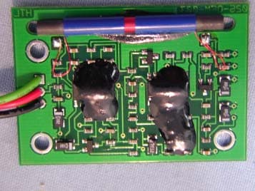
Click to zoom
Application Details
- Equipment Class
- DXX - Part 15 Low Power Communication Device Transmitter
- Date of Grant
- Jan 15, 2003
- Application Purpose
- Original Equipment
- Date of Application
- Jan 15, 2003
- Equipment Note
- 122 KHz Transmitter
- Frequency Range
- 0.12200000 - 0.12200000
- Company
- Zentan Technology Co., Ltd.
- Country
- Taiwan
Documents & Files
Document Text
Text extracted from the exhibit documents filed with the FCC. Open a document above to read the original.
Users Manual
POSITION THE CHEST TRANSMITTER 1 Attach the adjustable elastic strap to the transmitter. 2 Moisten the rubber electrodes on the underside of the belt as shown. Water or saliva can be used. 3 The transmitter should be positioned next to your skin with the Logo facing forwards in the middle of the chest, just below the breast. 4 Adjust the strap length to ensure a secure but comfortable fit. The transmitter is activated automatically when on the body and is deactivated automatically when removed. INSTALL THE RECEIVER Plug the receiver wire harness fully into the console wire harness. Press the receiver module into the console base until it snaps into place. Be careful to avoid pinching the wire harness. CARE AND MAINTENANCE 1 Thoroughly wipe your chest transmitter and allow the elastic strap to dry after each use. Story the chest transmitter in a cool dry place. 2 Do not expose your chest transmitter to direct sunlight for extended periods such as leaving it in a car. 3 Do not expose your chest transmitter to extremes of temperature above 122(50) or below 14(-10). Replace the transmitter battery Undo the battery hatch with a coin and remove the old battery. Ensure that the new battery is inserted into the hatch correctly with the plus sign facing the battery hatch. Check the rubber gasket is clean, correctly fitted and not damaged, then close the hatch securely. Caution: Before you start any exercise programme, you are advised to consult your doctor or physician. This device complies with part 15 of the FCC rules. Operation is subject to the following two conditions: (1) This device may not cause harmful interference (2) This device must accept any interference received, including interference that cause undesired operation. You are cautioned that changes or modifications not expressly approved by the party responsible for compliance could void your authority to operate the equipment.
Block Diagram
06/12/02 +V +VSignalAmplification/ Filtration ChestDetection PowerControl ECG 'R-wave'Detection Multiple Monostables 122kHzTelemetryDriver Power_on BatterySupply+3Volts Electrode RightElectrode Left Low FrequencyTuned Circuit Raw ECGSignal fromChest Cardiosport Contour Lite / Plus Transmitter 122kHz Magnetic Pulse Pulse Width(telemetry Control) R-wave detect timing Pulse Filtered ECGsignal (no noise) Block Diagram +V +V
External Photos
Spectrum Research & Testing Lab., Inc. No. 101-10, Ling 8, Shan-Tong Li, Chung-Li City, Taoyuan, Taiwan Tel: 886-3-4987684 Fax:: 886-3-4986528 PHOTOS OF EUT (Transmitter Part)
ID Label/Location Info
FCC ID Location FCC ID: QSW122K
Internal Photos
Spectrum Research & Testing Lab., Inc. No. 101-10, Ling 8, Shan-Tong Li, Chung-Li City, Taoyuan, Taiwan Tel: 886-3-4987684 Fax:: 886-3-4986528 PHOTOS OF EUT (Transmitter Part) Spectrum Research & Testing Lab., Inc. No. 101-10, Ling 8, Shan-Tong Li, Chung-Li City, Taoyuan, Taiwan Tel: 886-3-4987684 Fax:: 886-3-4986528 PHOTOS OF EUT (Transmitter Part) Spectrum Research & Testing Lab., Inc. No. 101-10, Ling 8, Shan-Tong Li, Chung-Li City, Taoyuan, Taiwan Tel: 886-3-4987684 Fax:: 886-3-4986528 PHOTOS OF EUT (Receiver Part) Spectrum Research & Testing Lab., Inc. No. 101-10, Ling 8, Shan-Tong Li, Chung-Li City, Taoyuan, Taiwan Tel: 886-3-4987684 Fax:: 886-3-4986528 PHOTOS OF EUT (Receiver Part)
Operational Description
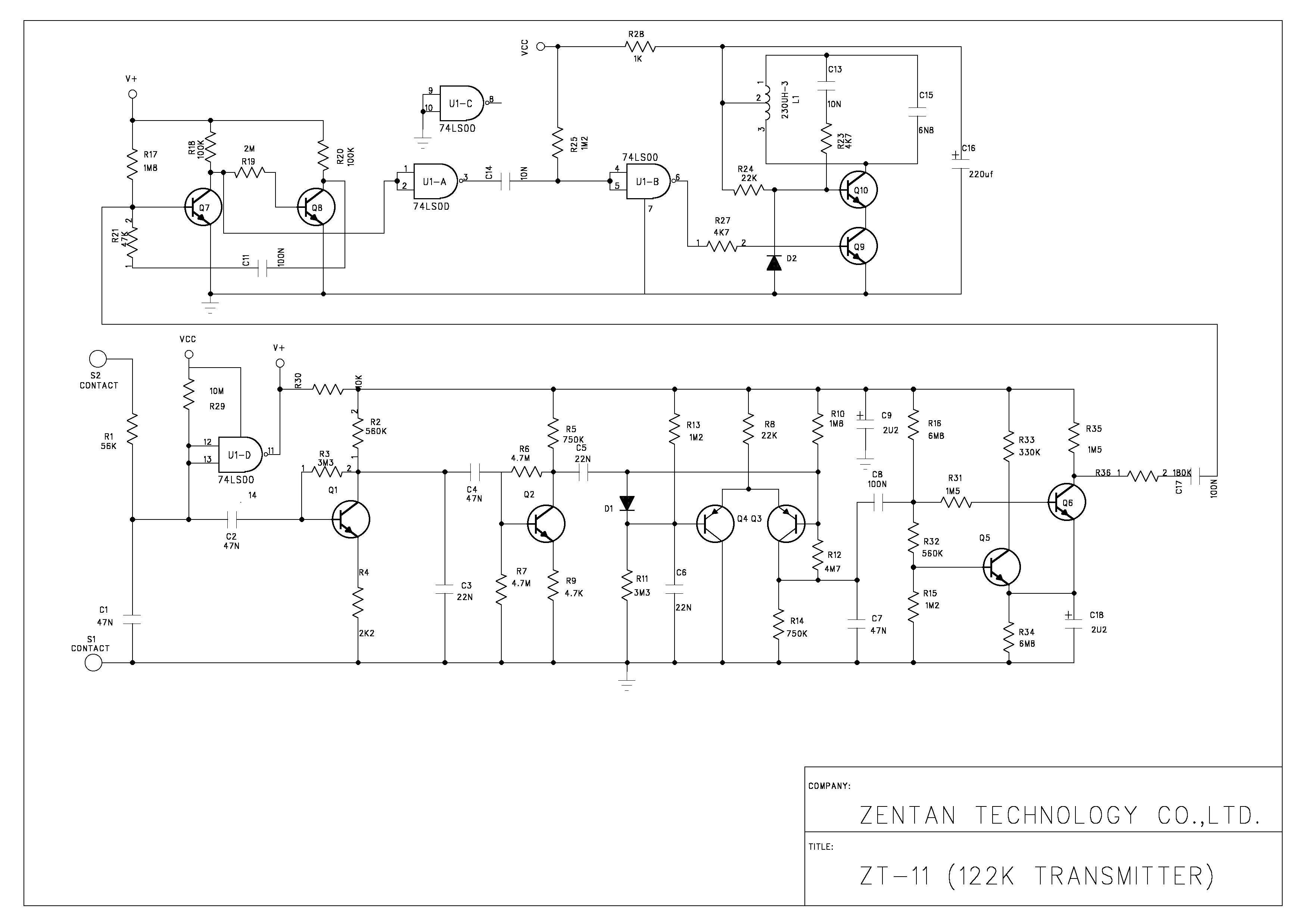
Operational Description of the equipment The EUT is the transmitter part of a chest transmitter which can detect heartbeat automatically when on the body. The detailed circuit function are described as below: PRODUCT 122 KHz transmitter MODEL NO. ZT-11 POWER SUPPLY DC 3V from Lithium Battery CABLE N/A I/O PORT N/A FREQUENCY BAND 9kHz-490kHz CARRIER FREQUENCY 122kHz±10% NUMBER OF CHANNEL 1 CHANNEL SPACING 0 RF OUTPUT POWER 31nW MODULATION TYPE Pulse ANTENNA TYPE Coils wound on ferrite cores and soldered to transmitter. 1 Moisten the rubber electrodes on the underside of the belt as shown. Water or saliva can be used. 2 The transmitter should be positioned next to your skin with the Logo facing forwards in the middle of the chest, just below the breast. 3 The EUT can detect heartbeats and filter signals, then transmit signals to receiver part by self-oscillating transmitter circuit (EUT).
Test Report
Spectrum Research & Testing Lab., Inc. No. 101-10, Ling 8, Shan-Tong Li, Chung-Li City, Taoyuan, Taiwan TEST REPORT Reference No.:A02112210 Report No.:FCCA02112210 Page: 1 of 1 Date: Dec. 27, 2002 Lab Code: 200099-0 FCC ID : QSW122K Product Name: 122 KHz transmitter Model Number: ZT-11 Applicant: ZENTAN TECHNOLOGY CO., LTD. NO. 92, HSING-SHENG RD., CHIA-LI CHENG, TAINAN HSIEN, TAIWAN, R.O.C. Date of Receipt: Dec. 08, 2002 Finished date of Test: Dec. 20, 2002 Applicable Standards: 47 CFR Part 15, Subpart C ANSI C63.4:1992 We, Spectrum Research & Testing Laboratory Inc., hereby certify that one sample of the above was tested in our laboratory with positive results according to the above-mentioned standards. The records in the report are an accurate account of the results. Details of the results are given in the subsequent pages of this report. Checked By : , Date: Approved By : (Wolfgang Huang) , Date: ( Harris W. Lai, Director ) Spectrum Research & Testing Lab., Inc. No. 101-10, Ling 8, Shan-Tong Li, Chung-Li City, Taoyuan, Taiwan TEST REPORT Reference No.:A02112210 Report No.: FCCA02112210 Page: 2 of 2 Date: Dec. 27, 2002 FCC ID : QSW122K Table of Contents 1. DOCUMENT POLICY AND TEST STATEMENT.......................................................3 1.1 DOCUMENT POLICY....................................................................................................3 1.2 TEST STATEMENT........................................................................................................3 2. DESCRIPTION OF EUT AND TEST MODE...............................................................4 2.1 GENERAL DESCRIPTION OF EUT............................................................................4 2.2 DESCRIPTION OF EUT INTERNAL DEVICE...........................................................4 2.3 DESCRIPTION OF TEST MODE.................................................................................4 2.4 DESCRIPTION OF SUPPORT UNIT..........................................................................5 3. DESCRIPTION OF APPLIED STANDARDS..............................................................6 4. RADIATED EMISSION TEST.......................................................................................6 4.1 RADIATED EMISSION LIMIT.......................................................................................6 4.2 TEST EQUIPMENT........................................................................................................7 4.3 TEST SET-UP.................................................................................................................8 4.4 TEST PROCEDURE......................................................................................................9 4.5 EUT OPERATING CONDITION...................................................................................9 4.6 RADIATED EMISSION TEST RESULT.....................................................................10 5. OCCUPIED BANDWIDTH TEST................................................................................12 5.1 TEST EQUIPMENT......................................................................................................12 5.2 TEST SET-UP...............................................................................................................13 5.3 TEST PROCEDURE....................................................................................................14 5.4 EUT OPERATING CONDITION.................................................................................14 5.5 OCCUPIED BANDWIDTH TEST RESULT...............................................................15 6 TIME DOMAIN AND DUTY CYCLE TEST...................................................................16 6.1 TEST EQUIPMENT......................................................................................................16 6.2 TEST SET-UP...............................................................................................................16 6.3 TEST PROCEDURE....................................................................................................16 6.4 EUT OPERATING CONDITION.................................................................................16 6.5 TIME DOMAIN AND DUTY CYCLE TEST RESULT...............................................17 7 TERMS OF ABRIVATION.............................................................................................20 Spectrum Research & Testing Lab., Inc. No. 101-10, Ling 8, Shan-Tong Li, Chung-Li City, Taoyuan, Taiwan TEST REPORT Reference No.:A02112210 Report No.: FCCA02112210 Page: 3 of 3 Date: Dec. 27, 2002 FCC ID : QSW122K 1. DOCUMENT POLICY AND TEST STATEMENT 1.1 DOCUMENT POLICY - The report shall not be reproduced except in full, without the written approval of SRT Lab, Inc. - The report must not be used by the applicant to claim that the product is endorsed by NVLAP. - The NVLAP logo applies only to the applicable standards specified in this report. 1.2 TEST STATEMENT - The test results in the report apply only to the unit tested by SRT Lab. - There was no deviation from the requirements of test standards during the test. - The heartbeat simulator (see the test photo) was produced signal to EUT during the test. - DC power source, 3V from Lithium battery, was used during the test. Spectrum Research & Testing Lab., Inc. No. 101-10, Ling 8, Shan-Tong Li, Chung-Li City, Taoyuan, Taiwan TEST REPORT Reference No.:A02112210 Report No.: FCCA02112210 Page: 4 of 4 Date: Dec. 27, 2002 FCC ID : QSW122K 2. DESCRIPTION OF EUT AND TEST MODE 2.1 GENERAL DESCRIPTION OF EUT PRODUCT 122 KHz transmitter MODEL NO. ZT-11 POWER SUPPLY DC 3V from Lithium Battery CABLE N/A I/O PORT N/A FREQUENCY BAND 9kHz-490kHz CARRIER FREQUENCY 122kHz±10% NUMBER OF CHANNEL 1 CHANNEL SPACING 0 RF OUTPUT POWER 31nW MODULATION TYPE Pulsed ANTENNA TYPE Coils wound on ferrite cores and soldered to transmitter. NOTE The EUT is the transmitter part of a chest transmitter whic…
Text truncated - open the document above for the full version.
Test Setup Photos
Spectrum Research & Testing Lab., Inc. No. 101-10, Ling 8, Shan-Tong Li, Chung-Li City, Taoyuan, Taiwan TEST REPORT Reference No.:A02112210 Report No.:FCCA02112210 Page: 1 of 2 Date: Dec. 27, 2002 6. PHOTOS OF TESTING - Raditated test (Below 30MHz) Lab Code: 200099-0 FCC ID : QSW122K Spectrum Research & Testing Lab., Inc. No. 101-10, Ling 8, Shan-Tong Li, Chung-Li City, Taoyuan, Taiwan TEST REPORT Reference No.:A02112210 Report No.: FCCA02112210 Page: 2 of 2 Date: Dec. 27, 2002 FCC ID : QSW122K - Raditated test
Contact Information
Applicant
Winner Chen(General Manager)
Test Firm
Spectrum Research & Testing Laboratory, Inc.Linda Chang
Technical Specifications
| # | Rule Parts | Frequency Range | Power Output |
|---|---|---|---|
| 1 | 15C | 0.122 MHz - 0.122 MHz | - |
Other Applications from Zentan Technology Co., Ltd.

QSWZE1
Apr 14, 2021Two Channel EMG Monitor
Equipment Class
DTS - Digital Transmission System
QSWST2GEN1
Jan 12, 2021Wireless Physical Fitness Monitor/Wireless Heart Rate Monitor
Equipment Class
DTS - Digital Transmission System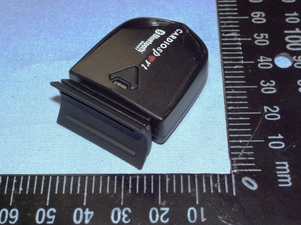
QSWBSPDCS
Sep 29, 2013SPEED (ZAS1B)/CADENCE (ZAS1B-C)
Equipment Class
DTS - Digital Transmission System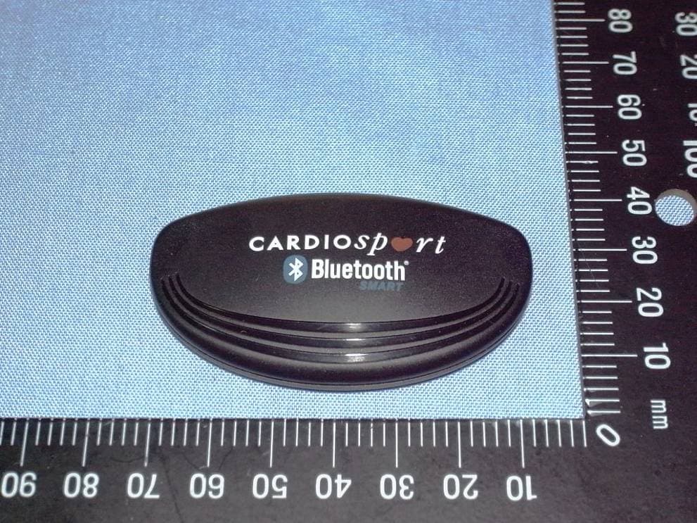
QSWBHRCS1
Feb 07, 2013TP3 SMART HEART RATE TRANSMITTER (ZT26B)
Equipment Class
DXX - Part 15 Low Power Communication Device Transmitter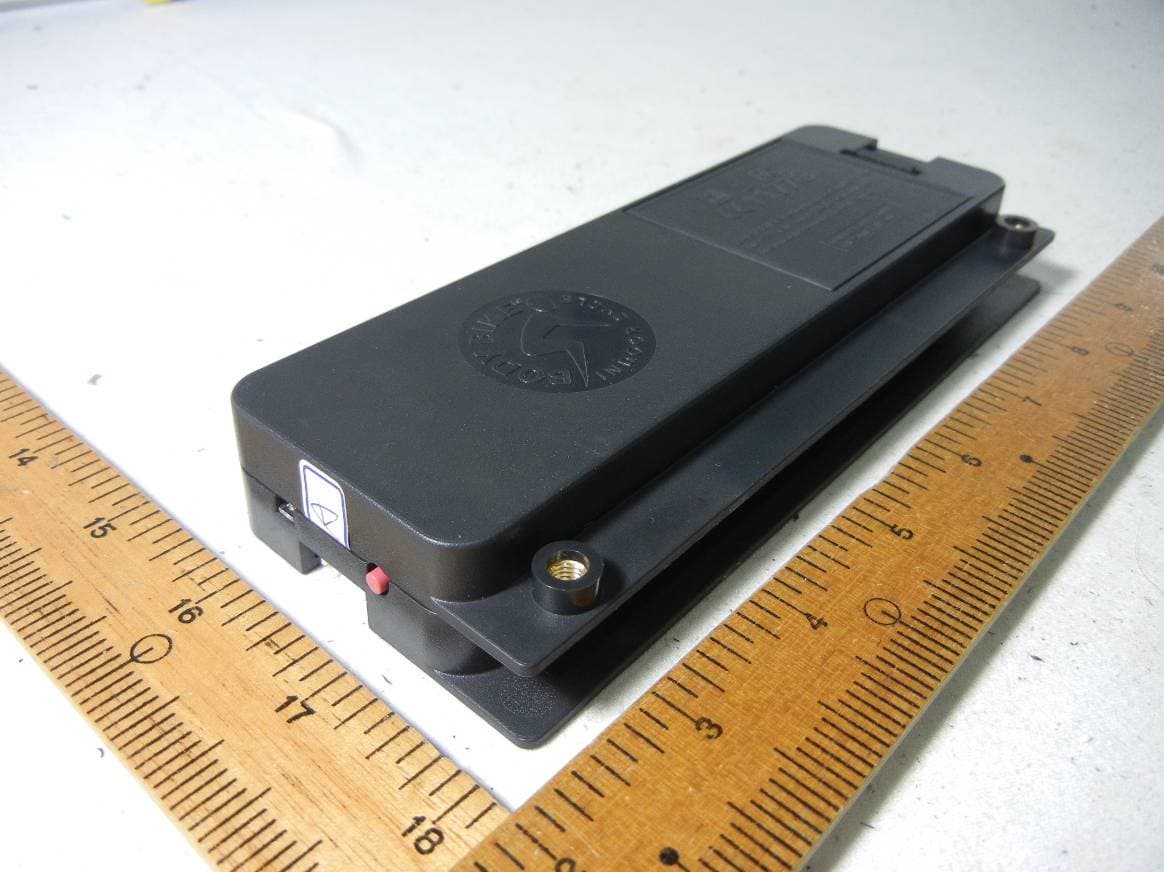
QSWAPWDBB
Jun 18, 2012Performance console and control box
Equipment Class
DXX - Part 15 Low Power Communication Device Transmitter