QSWSYSTEM122SYSTEM 122
Zentan Technology Co., Ltd.
Click to zoom
Application Details
- Equipment Class
- DXX - Part 15 Low Power Communication Device Transmitter
- Date of Grant
- Aug 16, 2004
- Application Purpose
- Original Equipment
- Date of Application
- Aug 16, 2004
- Equipment Note
- SYSTEM 122
- Frequency Range
- 0.12200000 - 0.12200000
- Company
- Zentan Technology Co., Ltd.
- Country
- Taiwan
Documents & Files
Document Text
Text extracted from the exhibit documents filed with the FCC. Open a document above to read the original.
Users Manual
2 Fusion 30 Fashionable heart rate monitor ideal for counting calories during exercise. Heart rate Time of Day Calendar Daily alarm Single heart zone setting Hi and Lo heart zone alarm 10 hour stopwatch 10 hour single & repeat countdown timer Time in Zone timer Heart rate recovery Calorie counter Scan showing maximum, average and minimum heart rate Fusion 20 Stylish heart rate monitor Ideal for general fitness training. Heart rate Time of Day Calendar Daily alarm Single heart zone setting Hi and Lo heart zone alarm 10 hour stopwatch 10 hour single & repeat countdown timer Scan showing maximum, average and minimum heart rate Lightweight transmitter belt included. 1 Contents Caution! 3 Important tips 3 Putting on the transmitter 3 About your Cardiosport System 122 Digital heart rate monitor 4 Quick start 4 Setting up your Fusion 20/30 5 · Entering the setting loop 5 · Time and calendar 5 · Daily alarm 6 · Heart rate zone high and low 6 · Countdown timer 7 Additional settings for Fusion 30 · Heart rate recovery (HRR) 7 · Calorie counter 8 Using your Fusion 20/30 9 · Switching On heart rate 9 · Switching Off heart rate 9 · Alarms: 9 Hourly 9 Daily 9 2 Out of zone 9 Heart rate recovery 10 · Using the stopwatch 10 · Using countdown timer 10 · Using scan: 11 Current session 11 Previous session 11 · Using time in zone (TiZ) 11 · Using the calorie counter 11 · The calorie counter ambient heart rate (AHR) Quick set 11 Training with your Fusion 20/30 12 Looking after your Fusion 14 Troubleshooting 14 Technical specification 16 Safety Statements 17 3 Caution Before you begin your exercise programme, get an assessment of your overall fitness level. You are advised to get clearance from your doctor that it is safe for you to exercise. Important Tips 1- You must make a long press of MODE in any main screen before you can get a heart rate reading. 2- If you get into a set up screen by mistake, a press and release of MODE takes you back to a main screen. Successive presses of MODE will scroll you through all main screens. 3- For proper heart rate readings, it is essential that there is sufficient moisture (water) between the electrodes on the transmitter and your skin. Insufficient moisture can cause no reading, frozen readings or erratic readings. 4- When using a wireless heart rate monitor near computers, electric motors, high voltage power lines, televisions, other heart rate monitors and mobile phones, erratic readings may occur. 5- You can wear the Fusion monitor when swimming, but do not push any of the buttons while the receiver (watch) is underwater. Putting on the transmitter · Attach one end of the adjustable elastic strap to the transmitter. · Moisten the rubber electrodes of the belt with either water or saliva as shown. · Position the transmitter on the chest just below the breastbone, with the Cardiosport logo the right way up. · Pass the elastic strap around your chest and attach to the other end of the transmitter. · Adjust the strap to give a close but comfortable fit. 4 About your Cardiosport System 122 Digital heart rate monitor The Cardiosport digital telemetry technology utilises a safe 122kHz low frequency system designed to deliver reliable coded heart rate information, so all you have to concentrate on is getting the most from your exercise. Each time you put on your chest transmitter and then press the MODE key until the Heart symbol appears, a code is randomly selected and transmitted to the watch receiver, thereafter the watch will lock on to this code plus the transmission interval to create an interlock. The code combined with the precise transmission interval results in the unique interlocking pairing between the chest transmitter and watch. The interlock code can be displayed by pressing and holding down the scan/rev key until the word CODE and a number appears on the screen. During the interlock process you should be at least 6 feet (1.8 metres) away from other Cardiosport System 122 heart rate monitors. If the interlock is lost for any reason, the watch will beep once to alert you and the heart rate display will go to Zero, in this case you should repeat the interlock process. Once the interlock is established, you can exercise in close proximity with other heart rate monitors safe in the knowledge that your monitor will display only your own heart rate only, not the heart rate of those around you. Quick Start Fusion 20/30 have a variety of features. To set these up you will need to read the instructions. However, if you just want to see how the heart rate feature works, follow these steps: 1 Put on the transmitter. 2 Attach the monitor to your wrist. 3 Press and hold the MODE key until the heart symbol appears. 5 4 After a few seconds the heart symbol will start flashing and your heart rate will appear. Setting up your Fusion 20 and 30 Impulse has one setting loop, which is entered from the Time of Day (ToD) screen. Once you enter this, each press and release of SELECT takes you to the next setting in the loop and returns to the Time of day screen. The setting loop for Fusion 20 is seconds, hours, minutes, day of week, month, date, alarm mode, daily alarm hour, daily alarm minute, heart zone high limit, heart zone low limit, countdown timer single or auto-repeat, countdown timer hours, minutes, seconds, then back to time of day. Fusion 30 has the following additions in the setting loop (after countdown timer seconds)–heart rate recovery high, heart rate recovery low, ambient heart rate, weight, age. Entering the setting loop In the ToD screen, press and hold SELECT until the seconds flash and the SELECT icon appears on the display. Note: A press of the MODE button at any stage in the setting loop takes you back to the main Screen for that setting. Setting Time and the calendar Press and release ST./FWD or SCAN to reset seconds to zero. Note: if seconds are over 30 when you reset, minutes will advance by 1. Press SELECT to move to…
Text truncated - open the document above for the full version.
Cover Letter(s)
Rev. 1/1/03 Federal Communications Commission Authorization and Evaluation Division Confidentiality Request regarding application for certification of FCC ID: QSWSYSTEM122 Pursuant to Sections 0.457 and 0.459 of the Commission’s Rules, we hereby request confidential treatment of information accompanying this application as outlined below: 1. Block Diagram 2. Schematics The above materials contain trade secrets and proprietary information not customarily released to the public. The public disclosure of these materials may be harmful to the applicant and provide unjustified benefits to its competitors. The applicant understands that pursuant to Section 0.457 of the Rules, disclosure of this application and all accompanying documentation will not be made before the date of the Grant for this application. Sincerely,
External Photos
PART I : TRANSMITTER PART PHOTOS OF EUT PART II : RECEIVER PART PHOTOS OF EUT
ID Label/Location Info
Sample of FCC ID Label FCC ID: QSWSYSTEM122 The device is so small that the Two-Part warning statement does not have to go on the device. It will be really hard to read. We remove the Two-Part statement from the device since we already have it in the manual. Sample of FCC DoC Label The device is so small that the Two-Part warning statement does not have to go on the device. It will be really hard to read. We remove the Two-Part statement from the device since we already have it in the manual.
Internal Photos
Spectrum Research & Testing Lab., Inc. No. 101-10, Ling 8, Shan-Tong Li, Chung-Li City, Taoyuan, Taiwan, R.O.C. Photo Page: 1 of 4 PART I : TRANSMITTER PART PHOTOS OF EUT Spectrum Research & Testing Lab., Inc. No. 101-10, Ling 8, Shan-Tong Li, Chung-Li City, Taoyuan, Taiwan, R.O.C. Photo Page: 2 of 4 PHOTOS OF EUT Spectrum Research & Testing Lab., Inc. No. 101-10, Ling 8, Shan-Tong Li, Chung-Li City, Taoyuan, Taiwan, R.O.C. Photo Page: 3 of 4 PART II : RECEIVER PART PHOTOS OF EUT Spectrum Research & Testing Lab., Inc. No. 101-10, Ling 8, Shan-Tong Li, Chung-Li City, Taoyuan, Taiwan, R.O.C. Photo Page: 4 of 4 PHOTOS OF EUT
Operational Description
FCC ID : QSWSYSTEM122 Operational Description of the equipment The EUT is the transmitter part of a chest transmitter which can detect eartbeat automatically when on the body. The detailed circuit function are described as below: PRODUCT SYSTEM 122 MODEL NO. ZT1CSC POWER SUPPLY DC 3.0V from Lithium battery CABLE N/A I/O PORT N/A FREQUENCY BAND 9kHz - 490kHz EMITTED FREQUENCY 122kHz NUMBER OF CHANNEL 1 CHANNEL SPACING 0 RF OUTPUT POWER 31nW MODULATION TYPE Pulse ANTENNA TYPE Coils wound on ferrite cores and soldered to transmitter ANTENNA GAIN 0dBi RANGE Up to 80cm (31.5 inches) to monitor BATTERY LIFE Approximately 2 years when used 60 min/day NOTE: 1 Moisten the rubber electrodes on the underside of the belt as shown. Water or saliva can be used. 2 The transmitter should be positioned next to your skin with the Logo facing forwards in the middle of the chest, just below the breast. 3 The EUT can detect heartbeats and filter signals, then transmit signals to receiver part by self-oscillating transmitter circuit (EUT).
Test Report
Spectrum Research & Testing Lab., Inc. No. 101-10, Ling 8, Shan-Tong Li, Chung-Li City, Taoyuan, Taiwan TEST REPORT Reference No.:A04052504 Report No.: FCCA04052504 Page: 2 of 20 Date:Jul. 30, 2004 FCC ID : QSWSYSTEM122 Table of Contents 1. DOCUMENT POLICY AND TEST STATEMENT......................................................3 1.1 DOCUMENT POLICY....................................................................................................3 1.2 TEST STATEMENT........................................................................................................3 1.3 EUT MODIFICATION.....................................................................................................3 2. DESCRIPTION OF EUT AND TEST MODE.............................................................4 2.1 GENERAL DESCRIPTION OF EUT............................................................................4 2.2 DESCRIPTION OF EUT INTERNAL DEVICE...........................................................4 2.3 DESCRIPTION OF TEST MODE.................................................................................4 2.4 DESCRIPTION OF SUPPORT UNIT..........................................................................5 3. DESCRIPTION OF APPLIED STANDARDS.............................................................5 4. RADIATED EMISSION TEST......................................................................................6 4.1 RADIATED EMISSION LIMIT.......................................................................................6 4.2 TEST EQUIPMENT........................................................................................................7 4.3 TEST SET-UP.................................................................................................................8 4.4 TEST PROCEDURE......................................................................................................9 4.5 EUT OPERATING CONDITION...................................................................................9 4.6 RADIATED EMISSION TEST RESULT...................................................................10 5. OCCUPIED BANDWIDTH TEST..............................................................................12 5.1 TEST EQUIPMENT.....................................................................................................12 5.2 TEST SET-UP..............................................................................................................13 5.3 TEST PROCEDURE...................................................................................................13 5.4 EUT OPERATING CONDITION................................................................................13 5.5 OCCUPIED BANDWIDTH TEST RESULT..............................................................14 6 TIME DOMAIN AND DUTY CYCLE TEST.................................................................15 6.1 TEST EQUIPMENT.....................................................................................................15 6.2 TEST SET-UP..............................................................................................................15 6.3 TEST PROCEDURE...................................................................................................15 6.4 EUT OPERATING CONDITION................................................................................15 6.5 TIME DOMAIN AND DUTY CYCLE TEST RESULT.............................................16 7. PHOTOS OF TESTING..............................................................................................19 8 TERMS OF ABRIVATION............................................................................................20 Spectrum Research & Testing Lab., Inc. No. 101-10, Ling 8, Shan-Tong Li, Chung-Li City, Taoyuan, Taiwan TEST REPORT Reference No.:A04052504 Report No.: FCCA04052504 Page: 3 of 20 Date:Jul. 30, 2004 FCC ID : QSWSYSTEM122 1. DOCUMENT POLICY AND TEST STATEMENT 1.1 DOCUMENT POLICY - The report shall not be reproduced except in full, without the written approval of SRT Lab, Inc. - The report must not be used by the applicant to claim that the product is endorsed by NVLAP, TÜV, NEMKO and SRT. - The NVLAP logo applies only to the applicable standards specified in this report. 1.2 TEST STATEMENT - The test results in the report apply only to the unit tested by SRT Lab. - There was no deviation from the requirements of test standards during the test. - The heartbeat simulator (see the test photo) was produced signal to EUT during the test. - DC power source, 3V from Lithium battery, was used during the test. 1.3 EUT MODIFICATION - No modification in SRT Lab. Spectrum Research & Testing Lab., Inc. No. 101-10, Ling 8, Shan-Tong Li, Chung-Li City, Taoyuan, Taiwan TEST REPORT Reference No.:A04052504 Report No.: FCCA04052504 Page: 4 of 20 Date:Jul. 30, 2004 FCC ID : QSWSYSTEM122 2. DESCRIPTION OF EUT AND TEST MODE 2.1 GENERAL DESCRIPTION OF EUT PRODUCT SYSTEM 122 MODEL NO. ZT1CSC POWER SUPPLY DC 3.0V from Lithium battery CABLE N/A I/O PORT N/A FREQUENCY BAND 9kHz - 490kHz EMITTED FREQUENCY 122kHz NUMBER OF CHANNEL 1 CHANNEL SPACING 0 RF OUTPUT POWER 31nW MODULATION TYPE Pulse ANTENNA TYPE Coils wound on ferrite cores and soldered to transmitter ANTENNA GAIN 0dBi RANGE Up to 80cm (31.5 inches) to monitor BATTERY LIFE Approximately 2 years when used 60 min/day NOTE: The EUT is the transmitter part of a chest transmitter which can detect heartbeat automatically when on the body. For more detailed features, please refer to the User’s Manual of EUT. 2.2 DESCRIPTION OF EUT INTERNAL DEVICE DEVICE BRAND / MAKER MODEL # FCC ID/DOC REMARK N/A 2.3 DESCRIPTION OF TEST MODE N/A (It is only applicable to more than one test mode.) Spectrum Research & Testing Lab., Inc. No. 101-10, Ling 8, Shan-Tong Li, Chung-Li City, Taoyuan, Taiwan TEST REPORT Reference No.:A04052504 Report No.: FCCA04052504 Page: 5 of 20 Date:Jul. 30, 2004 FCC ID : QSWSYSTEM122 2.4 DESCRIPT…
Text truncated - open the document above for the full version.
Test Setup Photos
- Raditated test (Below 30MHz) - Raditated test (30 – 1000MHz)
Contact Information
Applicant
Winner Chen(General Manager)
Test Firm
Spectrum Research & Testing Lab.Linda Chiang
Technical Specifications
| # | Rule Parts | Frequency Range | Power Output |
|---|---|---|---|
| 1 | 15C | 0.122 MHz - 0.122 MHz | - |
Other Applications from Zentan Technology Co., Ltd.

QSWZE1
Apr 14, 2021Two Channel EMG Monitor
Equipment Class
DTS - Digital Transmission System
QSWST2GEN1
Jan 12, 2021Wireless Physical Fitness Monitor/Wireless Heart Rate Monitor
Equipment Class
DTS - Digital Transmission System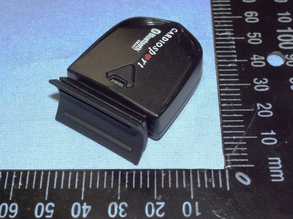
QSWBSPDCS
Sep 29, 2013SPEED (ZAS1B)/CADENCE (ZAS1B-C)
Equipment Class
DTS - Digital Transmission System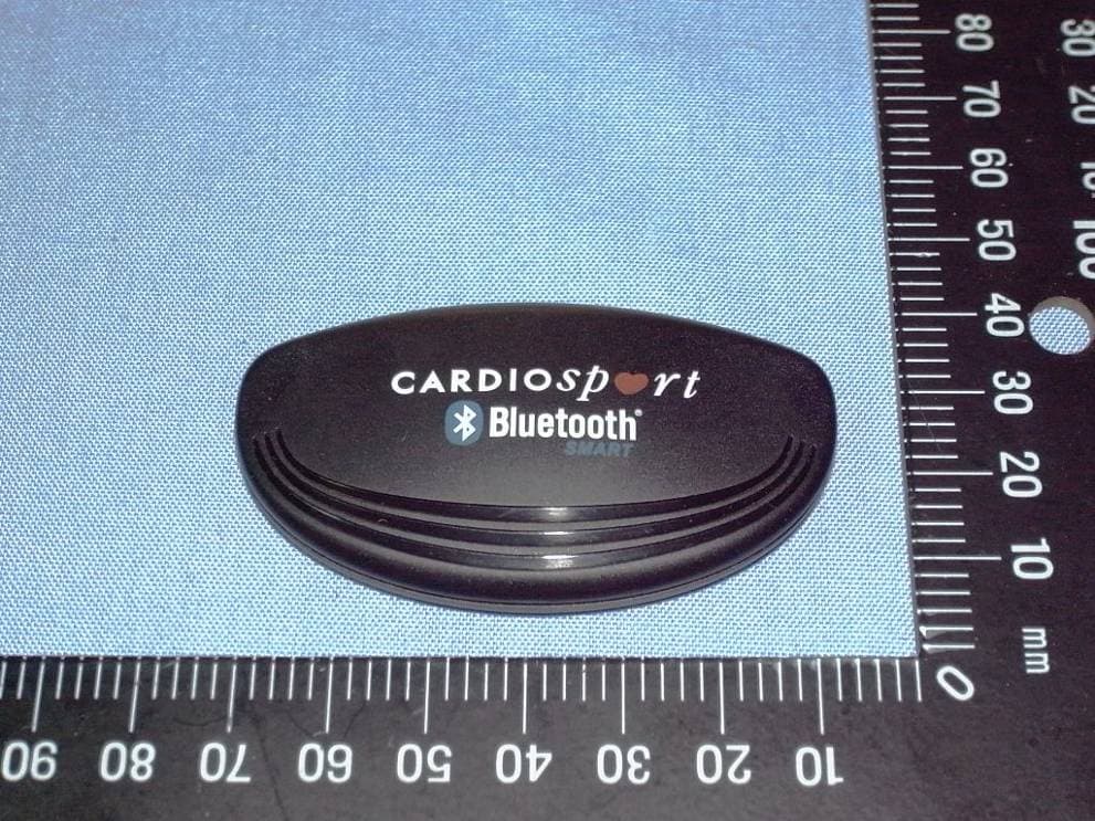
QSWBHRCS1
Feb 07, 2013TP3 SMART HEART RATE TRANSMITTER (ZT26B)
Equipment Class
DXX - Part 15 Low Power Communication Device Transmitter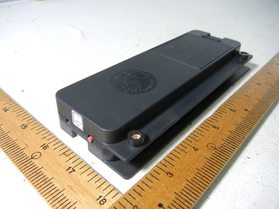
QSWAPWDBB
Jun 18, 2012Performance console and control box
Equipment Class
DXX - Part 15 Low Power Communication Device Transmitter