QSWSYSTEM122APMS
Zentan Technology Co., Ltd.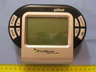
Click to zoom
Application Details
- Equipment Class
- DXX - Part 15 Low Power Communication Device Transmitter
- Date of Grant
- Oct 26, 2004
- Application Purpose
- Original Equipment
- Date of Application
- Oct 26, 2004
- Equipment Note
- PMS
- Frequency Range
- 0.12800000 - 0.12800000
- Company
- Zentan Technology Co., Ltd.
- Country
- Taiwan
Documents & Files
Document Text
Text extracted from the exhibit documents filed with the FCC. Open a document above to read the original.
Users Manual
© 2004 LeMond Fitness All rights reserved © 2004 LeMond Fitness. LeMond, RevMaster, and Pilot are registered trademarks of LeMond Fitness in the United States and other countries. Page 4 IMPORTANT SAFETY INSTRUCTIONS ! WARNING BEFORE BEGINNING THIS OR ANY EXERCISE PROGRAM, CONSULT YOUR PHYSICIAN. C ERTAIN EXERCISES, PROGRAMS, OR TYPES OF EQUIPMENT MAY NOT BE APPROPRIATE FOR ALL INDIVIDUALS, ESPECIALLY IF YOU ARE ABOVE 40 YEARS OF AGE, AND/OR HAVE PRE-EXISTING HEALTH , AND/OR ORTHOPEDIC MEDICAL CONDITIONS. YOUR PHYSICIAN CAN HELP YOU DETERMINE WHAT ACTIVITIES OR PROGRAMS ARE MOST SUITABLE FOR YOU. Page 5 This is to certify that the Pilot © wireless cadence meter is warranted by LeMond Fitness Inc. to be free of all defects in materials and workmanship. This warranty does not apply to any defect caused by negligence, misuse, accident, alteration, improper maintenance, or an “act of God.” The Pilot cadence meter can only be used on the RevMaster indoor cycling bike. Any attempts to use this meter on any other equipment voids the warranty. The Pilot carries a one year warranty on the meter and transmitter. Batteries are not warranted. Contact our Customer Service Department to report any problems. When calling, please be prepared to provide the customer service representative with the following information: Your name, the serial number of the inoperable unit, and the date(s) of purchase for the meter. If warranty replacement parts are shipped to you, you may be required to return the inoperable part. LeMond Fitness Inc. neither makes, assumes nor authorizes any representative or other person to make or assume for us, any other warranty whatsoever, whether expressed or implied, in connection with the sale, service, or shipment of our products. We reserve the right to make changes and improvements in our products without incurring any obligation to similarly alter products previously purchased. In order to maintain your product warranty and to ensure the safe and efficient operation of your cadence meter, only authorized replacement parts can be used. This warranty is void if parts other than those provided by LeMond Fitness are used. SPECIFICATIONS Cadence Meter Heart Rate Range:30 to 240 bpm (beats per minute) Heart Rate Accuracy:± 4 bpm Battery:2 AA batteries Battery Life:6 months to 1 year, depending on usage Transmitter Emitted Frequency:122 kHz Battery:3 AA batteries Battery Life:6 months to 1 year, depending on usage WARRANTY Page 6 CONTENTS Description7 Installation to the RevMaster9 Console9 Transmitter10 Magnet12 Display Window13 Quick Start Program15 Custom HR Training and Calorie Calculation16 Key Functions18 Cadence Training20 Heart Rate Training23 Start-Up Ride I - 30 Minutes26 Start-Up Ride II - 40 Minutes27 Troubleshooting28 Appendix FCC Compliance30 Changing the Console and Transmitter Codes and Dip Switch Codes31 Dip Switch Codes32 Console Codes33 NOTE: •Press any key to turn on the Pilot console. •Never disassemble the console or transmitter as it can not be reassembled. •The console is water resistant, not water proof. Do not deliberately place it in water. •To clean the console, wipe it off with a clean rag sprayed with diluted household cleaner. ○○○○○○○○○○○○○○○○○○○○○○○○○ ○○○○○○○○○○○○○○○ ○○○○○○○○○○○○○○○○○○○○○○ ○○○○○○○○○○○○○○○○○○○○ ○○○○○○○○○○○○○○○○○○○○○○ ○○○○○○○○○○○○○○○○○○○○○○ ○○○○○○○○○○○○○○○○○○○ ○○○○○○ ○○○○○○○○○○○○○○○○○○○○○ ○○○○○○○○○○○○○○○○○○○○ ○○○○○○○○○○○○○○○ ○○○○○○○○○○○○○○○○○○○○○○ ○○○○○○○○○○○○○○○○ ○○○○○○○○○○○○○○○○ ○○○○○○○○○○○○○○ ○○○○○○○○○○ ○○○○○○○○○○○○○○○○○○ Page 7 DESCRIPTION The Pilot assembly consists of a console, a magnet, and a transmitter. A sensor in the transmitter counts the number of times a magnet mounted in the right crank passes the sensor. The transmitter will then send a coded RF (radio frequency) signal to the console containing the measured values. The console has inboard receivers that pick up the signals from the transmitter and from telemetry (chest strap) heart rate signals. The heart rate is then shown in the display window. The console will track cadence (RPMs), speed (MPH/KPH), time, distance, and caloric expenditure. The console and the transmitter use AA batteries as a source of power. Install the supplied batteries in the console and in the transmitter prior to using. Console Battery Installation: 1.Remove the battery cover from the back of the console. 2.Insert 2 AA batteries into the battery compartment and reinstall the battery cover. Page 8 DESCRIPTION Transmitter Battery Installation: 1.Remove the battery cover from the transmitter. 2.Install 3 AA batteries in the battery compartment and reinstall the battery cover. NOTE: •Excessive use of the back light [ ]will drain the console batteries prematurely. •Expected life of the console batteries is 6 months to 1 year. •If the console battery power is low, then “BATT LOW” will be shown in the display window for 2 seconds after the display is turned on to inform you to change the console batteries. •Expected life of the transmitter batteries is 6 months to 1 year. Page 9 Handlebar Console Clamp Mounting Screws INSTALLATION OF THE PILOT THE CADENCE METER CAN ONLY BE INSTALLED ON A LEMOND REVMASTER BIKE. To install the meter, the following tools are needed: •Philips Screwdriver •4-mm Hex Key (supplied) Console Installation: 1.Ensure that the batteries are installed in the console and the console turns on. 2.Spread the bottom of the console clamp apart and clamp itback together over the top center of the handle bar. 3.Insert a mounting screw into each hole and use a 4-mm hex key to tighten the screws. Page 10 Transmitter: 1.Ensure that the batteries are installed in the transmitter. 2.Use the philips screwdriver to remove the 2 philips head screws from the back cover on the left side of the bike. 3.Using the 4-mm hex key remove the 4 belt cover hex head screws from the right side of the bike. 4.Remove the belt cover and place it inside up on the floor. 5.Peel the backing off the adhesive pad on th…
Text truncated - open the document above for the full version.
External Photos
Spectrum Research & Testing Lab., Inc. No. 101-10, Ling 8, Shan-Tong Li, Chung-Li City, Taoyuan, Taiwan, R.O.C. Photo Page: 1 of 2 PHOTOS OF EUT(RX) Spectrum Research & Testing Lab., Inc. No. 101-10, Ling 8, Shan-Tong Li, Chung-Li City, Taoyuan, Taiwan, R.O.C. Photo Page: 2 of 2 PHOTOS OF EUT(TX)
Internal Photos
Spectrum Research & Testing Lab., Inc. No. 101-10, Ling 8, Shan-Tong Li, Chung-Li City, Taoyuan, Taiwan, R.O.C. Photo Page: 1 of 7 PHOTOS OF EUT(RX) Spectrum Research & Testing Lab., Inc. No. 101-10, Ling 8, Shan-Tong Li, Chung-Li City, Taoyuan, Taiwan, R.O.C. Photo Page: 2 of 7 PHOTOS OF EUT Spectrum Research & Testing Lab., Inc. No. 101-10, Ling 8, Shan-Tong Li, Chung-Li City, Taoyuan, Taiwan, R.O.C. Photo Page: 3 of 7 PHOTOS OF EUT Spectrum Research & Testing Lab., Inc. No. 101-10, Ling 8, Shan-Tong Li, Chung-Li City, Taoyuan, Taiwan, R.O.C. Photo Page: 4 of 7 PHOTOS OF EUT Spectrum Research & Testing Lab., Inc. No. 101-10, Ling 8, Shan-Tong Li, Chung-Li City, Taoyuan, Taiwan, R.O.C. Photo Page: 5 of 7 PHOTOS OF EUT(TX) Spectrum Research & Testing Lab., Inc. No. 101-10, Ling 8, Shan-Tong Li, Chung-Li City, Taoyuan, Taiwan, R.O.C. Photo Page: 6 of 7 PHOTOS OF EUT(TX) Spectrum Research & Testing Lab., Inc. No. 101-10, Ling 8, Shan-Tong Li, Chung-Li City, Taoyuan, Taiwan, R.O.C. Photo Page: 7 of 7 PHOTOS OF EUT
Operational Description
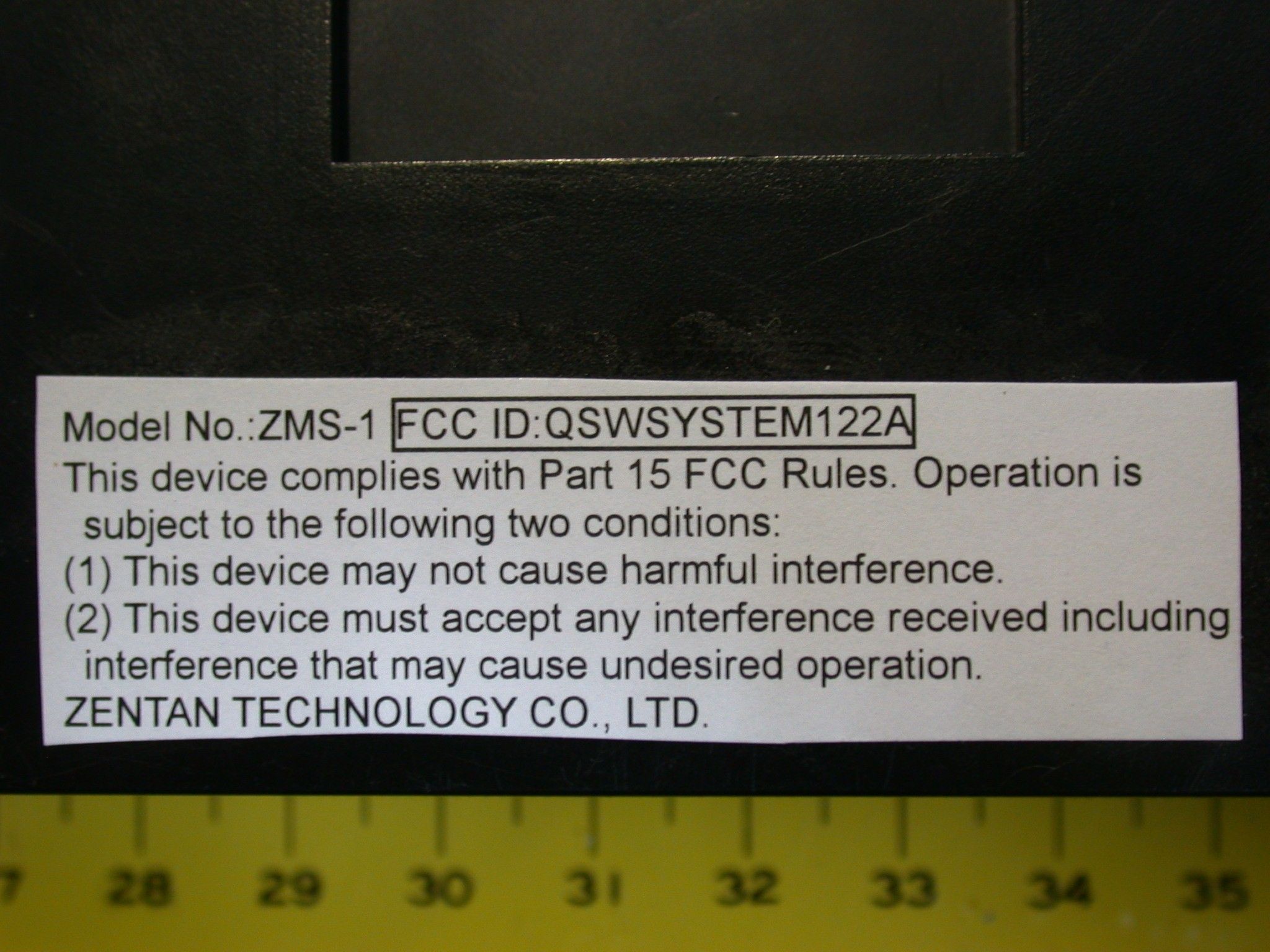
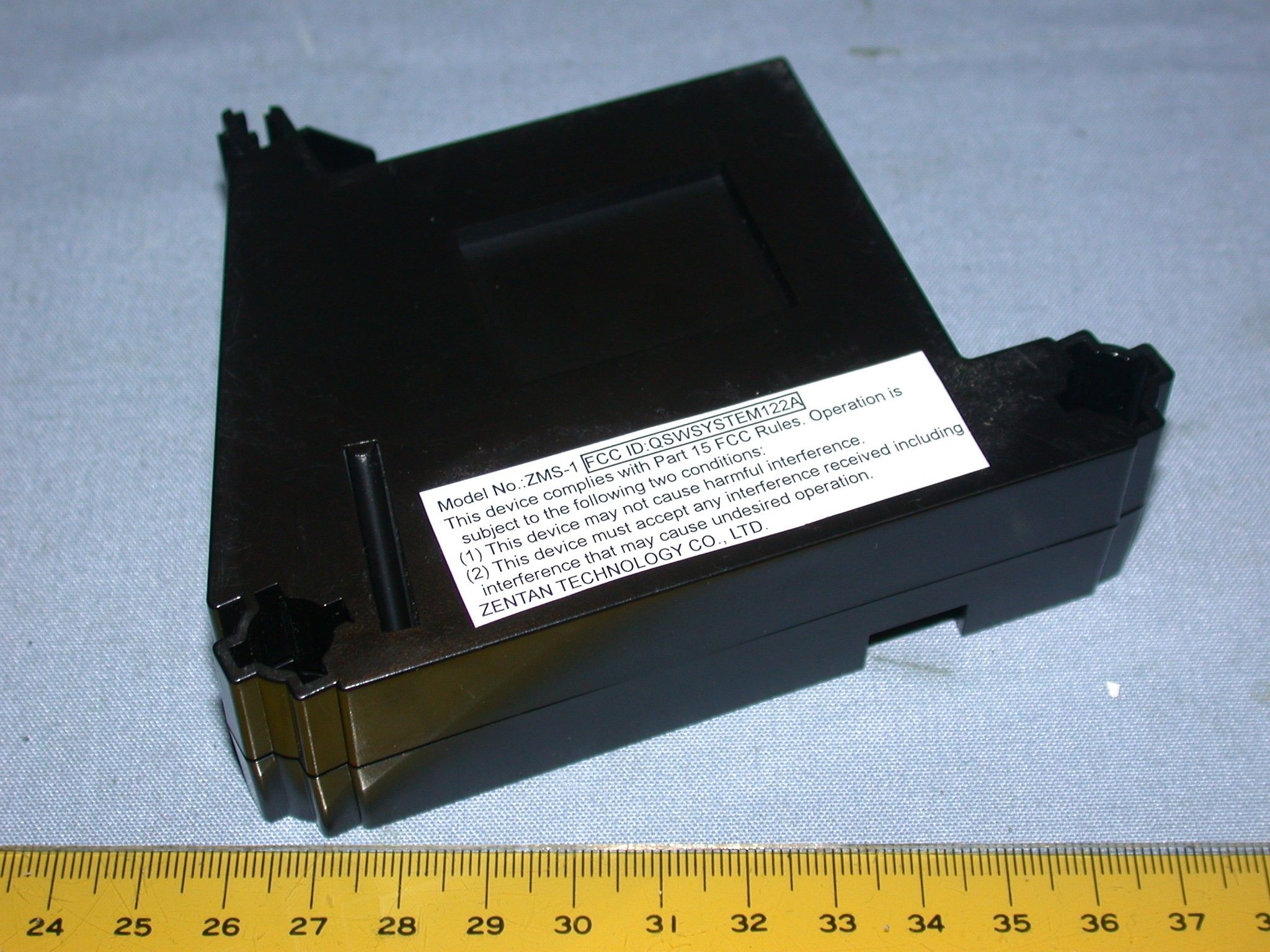
FCC ID : QSWSYSTEM122A The Pilot assembly consists of a console, a magnet, and a transmitter. A sensor in the transmitter counts the number of times a magnet mounted in the right crank passed the sensor. The transmitter will then send a coded RF(radio frequency) signal to the console containing the measured values. Operational Description of the equipment PRODUCT PMS MODEL NO. ZMS-1 POWER SUPPLY DC 4.5V, 0.5mA CABLE N/A I/O PORT N/A FREQUENCY BAND 127kHz , +/- 10% CARRIER FREQUENCY 122kHz±10% NUMBER OF CHANNEL 1 CHANNEL SPACING 0 MODULATION TYPE PULSE ANTENNA TYPE Coils wound on ferrite cores and soldered to transmitter.
Test Report
Spectrum Research & Testing Lab., Inc. No. 101-10, Ling 8, Shan-Tong Li, Chung-Li City, Taoyuan, Taiwan TEST REPORT Reference No.:A04052503 Report No.: FCCA04052503 Page: 2 of 16 Date: Jul. 12, 2004 FCC ID : QSWSYSTEM122A Table of Contents 1. DOCUMENT POLICY AND TEST STATEMENT ................................................ 3 1.1 DOCUMENT POLICY .........................................................................................3 1.2 TEST STATEMENT.............................................................................................3 2. DESCRIPTION OF EUT AND TEST MODE....................................................... 4 2.1 GENERAL DESCRIPTION OF EUT....................................................................4 2.2 DESCRIPTION OF EUT INTERNAL DEVICE.....................................................4 2.3 DESCRIPTION OF TEST MODE ........................................................................4 2.4 DESCRIPTION OF SUPPORT UNIT ..................................................................5 3. DESCRIPTION OF APPLIED STANDARDS ...................................................... 6 4. RADIATED EMISSION TEST ............................................................................. 6 4.1 RADIATED EMISSION LIMIT..............................................................................6 4.2 TEST EQUIPMENT.............................................................................................7 4.3 TEST SET-UP .....................................................................................................8 4.4 TEST PROCEDURE ...........................................................................................9 4.5 EUT OPERATING CONDITION ..........................................................................9 4.6 RADIATED EMISSION TEST RESULT .............................................................10 6 TIME DOMAIN AND DUTY CYCLE TEST .......................................................... 12 6.1 TEST EQUIPMENT...........................................................................................12 6.2 TEST SET-UP ...................................................................................................12 6.3 TEST PROCEDURE .........................................................................................12 6.4 EUT OPERATING CONDITION ........................................................................12 6.5 TIME DOMAIN AND DUTY CYCLE TEST RESULT .........................................13 7. PHOTOS OF TESTING.................................................................................... 14 7 TERMS OF ABRIVATION .................................................................................. 16 Spectrum Research & Testing Lab., Inc. No. 101-10, Ling 8, Shan-Tong Li, Chung-Li City, Taoyuan, Taiwan TEST REPORT Reference No.:A04052503 Report No.: FCCA04052503 Page: 3 of 16 Date: Jul. 12, 2004 FCC ID : QSWSYSTEM122A 1. DOCUMENT POLICY AND TEST STATEMENT 1.1 DOCUMENT POLICY - The report shall not be reproduced except in full, without the written approval of SRT Lab, Inc. - The report must not be used by the applicant to claim that the product is endorsed by NVLAP. - The NVLAP logo applies only to the applicable standards specified in this report. 1.2 TEST STATEMENT - The test results in the report apply only to the unit tested by SRT Lab. - There was no deviation from the requirements of test standards during the test. - The heartbeat simulator (see the test photo) was produced signal to EUT during the test. - DC power source, 3V from Lithium battery, was used during the test. Spectrum Research & Testing Lab., Inc. No. 101-10, Ling 8, Shan-Tong Li, Chung-Li City, Taoyuan, Taiwan TEST REPORT Reference No.:A04052503 Report No.: FCCA04052503 Page: 4 of 16 Date: Jul. 12, 2004 FCC ID : QSWSYSTEM122A 2. DESCRIPTION OF EUT AND TEST MODE 2.1 GENERAL DESCRIPTION OF EUT PRODUCT PMS MODEL NO. ZMS-1 POWER SUPPLY DC 4.5V, 0.5mA CABLE N/A I/O PORT N/A FREQUENCY BAND 127kHz , +/- 10% CARRIER FREQUENCY 127kHz±10% NUMBER OF CHANNEL 1 CHANNEL SPACING 0 MODULATION TYPE PULSE ANTENNA TYPE Coils wound on ferrite cores and soldered to transmitter. NOTE The EUT is the transmitter part of a chest transmitter which can detect heartbeat automatically when on the body. For more detailed features, please refer to the User’s Manual of EUT. 2.2 DESCRIPTION OF EUT INTERNAL DEVICE DEVICE BRAND / MAKER MODEL # FCC ID/DOC REMARK N/A 2.3 DESCRIPTION OF TEST MODE N/A (It is only applicable to more than one test mode.) Spectrum Research & Testing Lab., Inc. No. 101-10, Ling 8, Shan-Tong Li, Chung-Li City, Taoyuan, Taiwan TEST REPORT Reference No.:A04052503 Report No.: FCCA04052503 Page: 5 of 16 Date: Jul. 12, 2004 FCC ID : QSWSYSTEM122A 2.4 DESCRIPTION OF SUPPORT UNIT The EUT was configured by the requirement of ANSI C63.4. All interface ports were connected to the appropriate support units via specific cables. The support units and cables are listed below. NO DEVICE BRAND MODEL # FCC ID / DOC CABLE N/A NOTE For the actual test configuration, please refer to the photos of testing. Spectrum Research & Testing Lab., Inc. No. 101-10, Ling 8, Shan-Tong Li, Chung-Li City, Taoyuan, Taiwan TEST REPORT Reference No.:A04052503 Report No.: FCCA04052503 Page: 6 of 16 Date: Jul. 12, 2004 FCC ID : QSWSYSTEM122A 3. DESCRIPTION OF APPLIED STANDARDS The EUT is a kind of radio product and according to the specifications provided by the applicant, it must comply with the requirements of the following standards: 47 CFR Part 15, Subpart C ANSI C63.4:2003 All tests have been performed and recorded as per the above standards. 4. RADIATED EMISSION TEST 4.1 RADIATED EMISSION LIMIT All emission from EUT, including any network of conductors and apparatus connected thereto, shall not exceed the level of field strength specified below FCC Part 15, Subpart C Section 15.209. FREQUENCY (MHz) DISTANCE (m) FIELD STRENGTH ( μ V/m) 0.009 - 0.490 300 2400/F(kHz) 0.490-1.…
Text truncated - open the document above for the full version.
Test Setup Photos
Spectrum Research & Testing Lab., Inc. No. 101-10, Ling 8, Shan-Tong Li, Chung-Li City, Taoyuan, Taiwan, R.O.C. Photo Page: 1 of 2 7. PHOTOS OF TESTING - Raditated test (Below 30MHz) Spectrum Research & Testing Lab., Inc. No. 101-10, Ling 8, Shan-Tong Li, Chung-Li City, Taoyuan, Taiwan, R.O.C. Photo Page: 2 of 2 - Raditated test
Contact Information
Applicant
Winner Chen(General Manager)
Test Firm
Spectrum Research & Testing Lab.Linda Chiang
Technical Specifications
| # | Rule Parts | Frequency Range | Power Output |
|---|---|---|---|
| 1 | 15C | 0.128 MHz - 0.128 MHz | - |
Other Applications from Zentan Technology Co., Ltd.

QSWZE1
Apr 14, 2021Two Channel EMG Monitor
Equipment Class
DTS - Digital Transmission System
QSWST2GEN1
Jan 12, 2021Wireless Physical Fitness Monitor/Wireless Heart Rate Monitor
Equipment Class
DTS - Digital Transmission System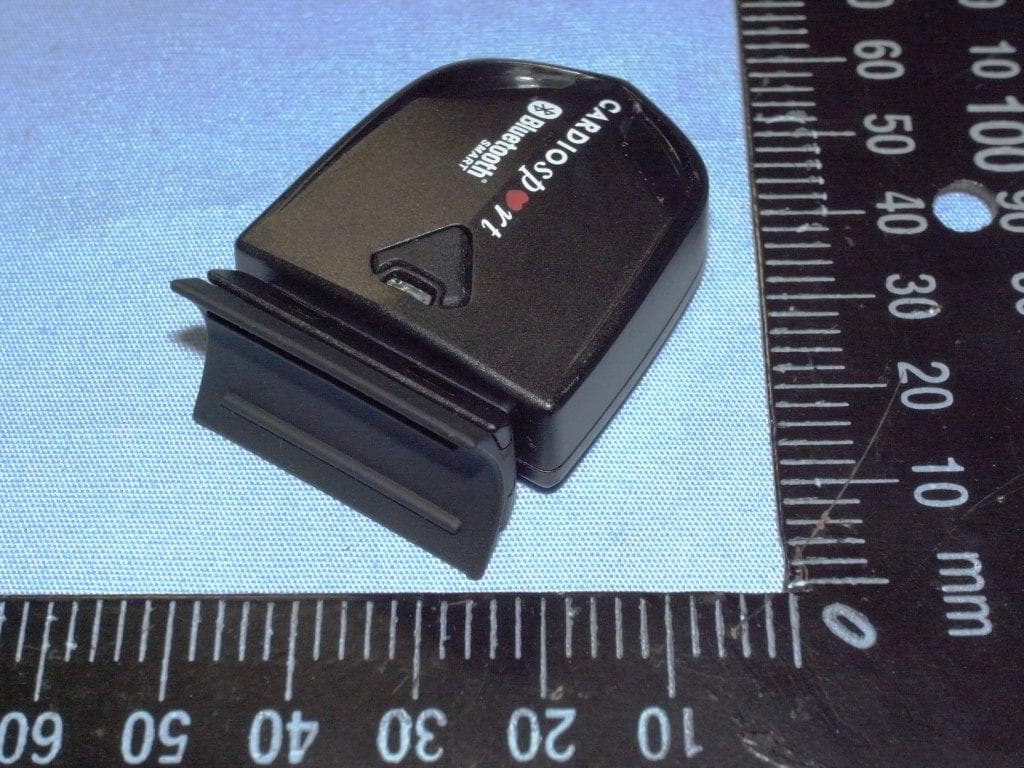
QSWBSPDCS
Sep 29, 2013SPEED (ZAS1B)/CADENCE (ZAS1B-C)
Equipment Class
DTS - Digital Transmission System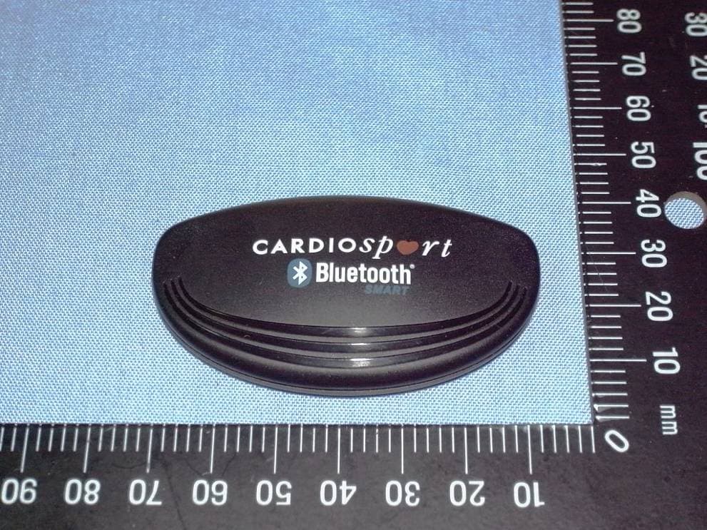
QSWBHRCS1
Feb 07, 2013TP3 SMART HEART RATE TRANSMITTER (ZT26B)
Equipment Class
DXX - Part 15 Low Power Communication Device Transmitter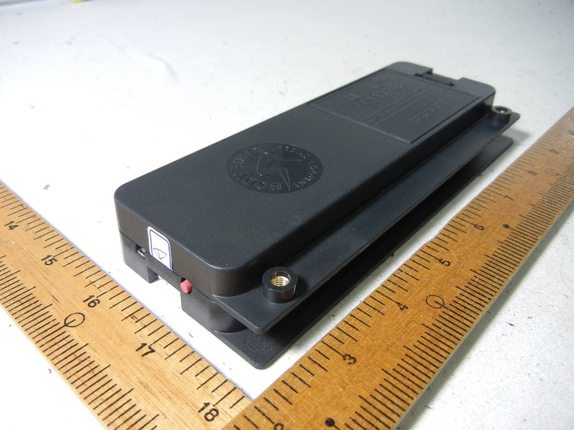
QSWAPWDBB
Jun 18, 2012Performance console and control box
Equipment Class
DXX - Part 15 Low Power Communication Device Transmitter