QT5-RFID113.56 MHz RFID Transceiver
Rimage Corporation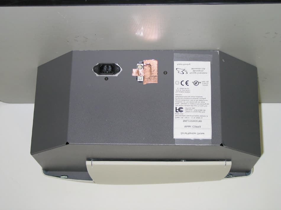
Click to zoom
Application Details
- Equipment Class
- DXX - Part 15 Low Power Communication Device Transmitter
- Date of Grant
- Feb 18, 2003
- Application Purpose
- Original Equipment
- Date of Application
- Feb 18, 2003
- Equipment Note
- 13.56 MHz RFID Transceiver
- Frequency Range
- 13.56000000 - 13.56000000
- Company
- Rimage Corporation
- Country
- United States
Documents & Files
Document Text
Text extracted from the exhibit documents filed with the FCC. Open a document above to read the original.
Users Manual
1. Instruction Manual The RFID1 is designed for use by Original Equipment Manufacturers (OEM) for inclusion into their products. There are no end user instructions necessary for use or maintenance. See the following pages for the integration and usage instructions. FCC ID: QT5-RFID1 OFFICE CORRESPONDENCE 7725 Washington Ave. South; Minneapolis, Minnesota 55349 USA Phone: (952) 944-8144 Fax: (952) 944-7808 OEM Integration Instructions for Rimage P/N 626371-001, FCC ID: QT5-RFID1 File: RFID1 OEM.doc, 06-Feb-03 Phil Salisbury Page 1 of 1 CONFIDENTIAL, not to be released without written authorization from Rimage Corporation. 1. General The RFID1 device is used by Original Equipment Manufacturers (OEM) to integrate close range (2-inch or less) ISO 15693 transponder communications into a product. There are no usage, calibration, or maintenance instructions necessary for the end user. There are no calibrations necessary for the OEM. There are no special accessories required for either the OEM or end user. 2. Identification Nameplate Requirements The following information must be included as part of the permanent and end user visible equipment identification nameplate. These markings may only be applied after the OEM has tested to ensure compliance with the relevant national standards. ! This device contains a radio transmitter FCC ID: QT5-RFID1; IC: 4496A-RFID1. This device complies with part 15 of the FCC Rules. Operation is subject to the following two conditions: (1) This device may not cause harmful interference, and (2) this device must accept any interference received, including interference that may cause undesired operation. 3. Compliance Statement Requirements for User Documentation. The following information must be included in the end user documentation provided by the OEM. 4. Transceiver Control The RFID1 is based on the Texas Instruments RI-R6C-001A transceiver integrated circuit (IC). Control of this IC is specified in Texas Instruments document 11-07-21-001+S6700+Reference+Guide+V3.pdf . Rimage has developed controlling firmware and will work with the OEM to integrate that control into their product. The Rimage firmware sets up the IC and manages data communications between the IC and the transponder. Notice for the USA This device contains a radio transmitter FCC ID: QT5-RFID1. This device complies with part 15 of the FCC Rules. Operation is subject to the following two conditions: (1) This device may not cause harmful interference, and (2) this device must accept any interference received, including interference that may cause undesired operation. Any unauthorized modification to this equipment may result in the revocation by the FCC of the user’s authority to operate this equipment. Notice for Canada This product contains a radio transmitter IC: 4496A-RFID1 in conformance with RSS-210: Issue 5: 2001 . The term “IC” before the radio certification number only signifies that Industry Canada Technical specifications were met. Notice for Europe ! This product contains a radio transmitter (RFID1) in conformity with R&TTE directive 1999/5/EC through compliance with the following European Standards: EN 300 330-2 v1.1.1: 2001; EN 301 489-3:2002 Class B Limit. 1 June í02Appendix C. Register Definition 11-07-21-001 June 2002 HF Reader System Series 6000 S6700 Multi Protocol Transceiver IC RI-R6C-001A Reference Guide A TEXAS INSTRUMENTS TECHNOLOGY 2 S6700 Multi-Protocol Transceiver IC - Reference GuideJune í02 Edition Three - June 2002 This is the third edition of this manual. It describes the following product: S6700 Multi Protocol Transceiver IC RI-R6C-001A-02 Texas Instruments (TI) reserves the right to make changes to its products or services or to discontinue any product or service at any time without notice. TI provides cus- tomer assistance in various technical areas, but does not have full access to data concerning the use and applications of customer's products. Therefore, TI assumes no liability and is not responsible for customer applications or product or software design or performance relating to systems or applications incor- porating TI products. In addition, TI assumes no liability and is not responsible for infringement of patents and/or any other intellectual or industrial property rights of third parties, which may result from assistance provided by TI. TI products are not designed, intended, authorized or warranted to be suitable for life support applications or any other life critical applications which could involve poten- tial risk of death, personal injury or severe property or environmental damage. The TIRIS and TI-RFID logos, the words TIRIS, TI-RFID and Tag-it are trademarks or registered trademarks of Texas Instruments Incorporated. Copyright 2002 Texas Instruments Incorporated (TI) This document may be downloaded onto a computer, stored and duplicated as nec- essary to support the use of the related TI products. Any other type of duplication, circulation or storage on data carriers in any manner not authorised by TI represents a violation of the applicable copyright laws and shall be prosecuted. 3 June ë02Preface About This Manual This reference guide for the S6700 Multi Protocol Transceiver IC is designed for use by TI partners who are engineers experienced with Radio Frequency Identification Devices (RFID). Regulatory, safety and warranty notices that must be followed are given in Chapter 5. Conventions If You Need Assistance For more information, please contact the sales office or distributor nearest you. This contact information can be found on our web site at: http://www.ti-rfid.com WARNING: A WARNING IS USED WHERE CARE MUST BE TAKEN, OR A CERTAIN PROCEDURE MUST BE FOLLOWED IN ORDER TO PRE- VENT INJURY OR HARM TO YOUR HEALTH. CAUTION: This indicates information on conditions which must be met, or a procedure which must be followed, which if not heeded could cause permanent damage to the equipment or software. Note: Indicates conditions which must be met…
Text truncated - open the document above for the full version.
Cover Letter(s)
19 February 2003 TCB TÜV America Inc 10040 Mesa Rim Road San Diego CA 92121 RE: FCC ID: QT5-RFID1 submittal as modular device (Rimage Corporation) 1. The modular transmitter must have its own RF shielding. This is intended to ensure that the module does not have to rely upon the shielding provided by the device into which it is installed in order for all modular transmitter emissions to comply with Part 15 limits. It is also intended to prevent coupling between the RF circuitry of the module and any wires or circuits in the device into which the module is installed. Such coupling may result in non-compliant operation. The EUT has all of the RF shielding it requires to meet the FCC limits. It does not rely on the shielding of any host unit it will be installed in. 2. The modular transmitter must have buffered modulation/data inputs (if such inputs are provided) to ensure that the module will comply with Part 15 requirements under conditions of excessive data rates or over-modulation. All buffering is handled in the TI chip. 3. The modular transmitter must have its own power supply regulation. This is intended to ensure that the module will comply with Part 15 requirements regardless of the design of the power supplying circuitry in the device into which the module is installed. All power is regulated in the module. 4. The modular transmitter must comply with the antenna requirements of Section 15.203 and 15.204(c). The antenna must either be permanently attached or employ a “unique” antenna coupler (at all connections between the module and the antenna, including the cable). Any antenna used with the module must be approved with the module, either at the time of initial authorization or through a Class II permissive change. The “professional installation” provision of Section 15.203 may not be applied to modules. The antenna is in the pc board. 5. The modular transmitter must be tested in a stand-alone configuration, i.e., the module must not be inside another device during testing. This is intended to demonstrate that the module is capable of complying with Part 15 emission limits regardless of the device into which it is eventually installed. Unless the transmitter module will be battery powered, it must comply with the AC line conducted requirements found in Section 15.207. AC or DC power lines and data input/output lines connected to the module must not contain ferrites, unless they will be marketed with the module (see Section 15.27(a)). The length of these lines shall be length typical of actual use or, if that length is unknown, at least 10 centimeters to insure that there is no coupling between the case of the module and supporting equipment. Any accessories, peripherals, or support equipment connected to the module during testing shall be unmodified or commercially available (see Section 15.31(i)). The EUT was tested for radiated emission requirements in a stand-alone configuration and meets the requirements. The AC line conducted emissions were made with the EUT installed in a representative host, as it is a 5 VDC powered device, which would be exempt from the AC line conducted requirements. 6. The modular transmitter must be labeled with its own FCC ID number, and, if the FCC ID is not visible when the module is installed inside another device, then the outside of the device into which the module is installed must also display a label referring to the enclosed module. This exterior label can use wording such as the following: “Contains Transmitter Module FCC ID: XYZMODEL1” or “Contains FCC ID: XYZMODEL1.” Any similar wording that expresses the same meaning may be used. The Grantee may either provide such a label, an example of which must be included in the application for equipment authorization, or, must provide adequate instructions along with the module which explain this requirement. In the latter case, a copy of these instructions must be included in the application for equipment authorization. The transmitter has its own FCC ID label, + the mfr will put the label on the outside of whatever device it goes into. 7. The modular transmitter must comply with any specific rule or operating requirements applicable to the transmitter and the manufacturer must provide adequate instructions along with the module to explain any such requirements. A copy of these instructions must be included in the application for equipment authorization. For example, there are very strict operational and timing requirements that must be met before a transmitter is authorized for operation under Section 15.231. For instance, data transmission is prohibited, except for operation under Section 15.231(e), in which case there are separate field strength level and timing requirements. Compliance with these requirements must be assured. The test report shows the transmitter meets all the pertinent requirements, 15.225 has no additional specific requirements that need be addressed. 8. The modular transmitter must comply with any applicable RF exposure requirements. For example, FCC Rules in Sections 2.1091, 2.1093 and specific Sections of Part 15, including 15.319(i), 15.407(f), 15.253(f) and 15.255(g), require that Unlicensed PCS, UNII and millimeter wave devices perform routine environmental evaluation for RF Exposure to demonstrate compliance. In addition, spread spectrum transmitters operating under Section 15.247 are required to address RF Exposure compliance in accordance with Section 15.247(b)(4). Modular transmitters approved under other Sections of Part 15, when necessary, may also need to address certain RF Exposure concerns, typically by providing specific installation and operating instructions for users, installers and other interested parties to ensure compliance. The transmitter meets RF exposure requirements. Filename: modular letter.doc Directory: C: Template: C:\WINDOWS\Application Data\Microsoft\Templates\Normal.dot Title: 19 February 2003 Subject: Author: Wild River Lab Keywords: Commen…
Text truncated - open the document above for the full version.
External Photos
FCC ID: FCC ID: QT5-RFID1 Page 1 of 4 Rimage RFID1x – Front View FCC ID: FCC ID: QT5-RFID1 Page 2 of 4 Rimage RFID1x – Right View FCC ID: FCC ID: QT5-RFID1 Page 3 of 4 Rimage RFID1x – Rear View FCC ID: FCC ID: QT5-RFID1 Page 4 of 4 Rimage RFID1x – Left View
ID Label/Location Info
FCC ID: QT5-RFID1 Page 2 of 4 RFID1 Printed Circuit Board Front (FCC ID marking is permanent by label or silk-screen.) Identification Nameplate This is the CDPR3 identification nameplate and is typical for any system containing the RFID1. Due to it’s small size, the RFID1 only contains the FCC ID. Serial Number Sticker Model: CDPR3 MAL0123456789 This device complies with part 15 of the FCC Rules. Operation is subject to the following two conditions: (1) This device may not cause harmful interference, and (2) this device must accept any interference received, including interference that may cause undesired operation. Power: 100 - 240 V~ , 0.7 A, 50/60 Hz See instruction manual for proper selection of power cord. Patent Pending Tested to Comply with FCC Standards. FOR HOME OR OFFICE USE ! Rimage Corporation Minneapolis, Minnesota USA This product contains FCC ID: QT5-RFID1 IC: 4496A-RFID1 LISTED E183113 7R04 ITE FCC ID: QT5-RFID1 Label Placement: FCC ID marking is permanent by label or silk-screen.
Internal Photos
FCC ID: QT5-RFID1 Page 1 of 4 RFID1 Internal View FCC ID: QT5-RFID1 Page 2 of 4 RFID1 Printed Circuit Board Front (FCC ID marking is permanent by label or silk-screen.) FCC ID: QT5-RFID1 Page 3 of 4 RFID1 Printed Circuit Board – Close up of Frequency carrier The integrated circuit marked RI-R6C-001A is the transceiver. The part marked 13.560 is the 13.56MHz crystal from that sets the 13.56MHz carrier frequency. FCC ID: QT5-RFID1 Page 4 of 4 RFID1 Printed Circuit Board Back
Test Report
19 February 2003 TCB TÜV America Inc 10040 Mesa Rim Road San Diego CA 92121 RE: FCC ID: QT5-RFID1 submittal as modular device (Rimage Corporation) 1. The modular transmitter must have its own RF shielding. This is intended to ensure that the module does not have to rely upon the shielding provided by the device into which it is installed in order for all modular transmitter emissions to comply with Part 15 limits. It is also intended to prevent coupling between the RF circuitry of the module and any wires or circuits in the device into which the module is installed. Such coupling may result in non-compliant operation. The EUT has all of the RF shielding it requires to meet the FCC limits. It does not rely on the shielding of any host unit it will be installed in. 2. The modular transmitter must have buffered modulation/data inputs (if such inputs are provided) to ensure that the module will comply with Part 15 requirements under conditions of excessive data rates or over-modulation. All buffering is handled in the TI chip. 3. The modular transmitter must have its own power supply regulation. This is intended to ensure that the module will comply with Part 15 requirements regardless of the design of the power supplying circuitry in the device into which the module is installed. All power is regulated in the module. 4. The modular transmitter must comply with the antenna requirements of Section 15.203 and 15.204(c). The antenna must either be permanently attached or employ a “unique” antenna coupler (at all connections between the module and the antenna, including the cable). Any antenna used with the module must be approved with the module, either at the time of initial authorization or through a Class II permissive change. The “professional installation” provision of Section 15.203 may not be applied to modules. The antenna is in the pc board. 5. The modular transmitter must be tested in a stand-alone configuration, i.e., the module must not be inside another device during testing. This is intended to demonstrate that the module is capable of complying with Part 15 emission limits regardless of the device into which it is eventually installed. Unless the transmitter module will be battery powered, it must comply with the AC line conducted requirements found in Section 15.207. AC or DC power lines and data input/output lines connected to the module must not contain ferrites, unless they will be marketed with the module (see Section 15.27(a)). The length of these lines shall be length typical of actual use or, if that length is unknown, at least 10 centimeters to insure that there is no coupling between the case of the module and supporting equipment. Any accessories, peripherals, or support equipment connected to the module during testing shall be unmodified or commercially available (see Section 15.31(i)). The EUT was tested for radiated emission requirements in a stand-alone configuration and meets the requirements. The AC line conducted emissions were made with the EUT installed in a representative host, as it is a 5 VDC powered device, which would be exempt from the AC line conducted requirements. 6. The modular transmitter must be labeled with its own FCC ID number, and, if the FCC ID is not visible when the module is installed inside another device, then the outside of the device into which the module is installed must also display a label referring to the enclosed module. This exterior label can use wording such as the following: “Contains Transmitter Module FCC ID: XYZMODEL1” or “Contains FCC ID: XYZMODEL1.” Any similar wording that expresses the same meaning may be used. The Grantee may either provide such a label, an example of which must be included in the application for equipment authorization, or, must provide adequate instructions along with the module which explain this requirement. In the latter case, a copy of these instructions must be included in the application for equipment authorization. The transmitter has its own FCC ID label, + the mfr will put the label on the outside of whatever device it goes into. 7. The modular transmitter must comply with any specific rule or operating requirements applicable to the transmitter and the manufacturer must provide adequate instructions along with the module to explain any such requirements. A copy of these instructions must be included in the application for equipment authorization. For example, there are very strict operational and timing requirements that must be met before a transmitter is authorized for operation under Section 15.231. For instance, data transmission is prohibited, except for operation under Section 15.231(e), in which case there are separate field strength level and timing requirements. Compliance with these requirements must be assured. The test report shows the transmitter meets all the pertinent requirements, 15.225 has no additional specific requirements that need be addressed. 8. The modular transmitter must comply with any applicable RF exposure requirements. For example, FCC Rules in Sections 2.1091, 2.1093 and specific Sections of Part 15, including 15.319(i), 15.407(f), 15.253(f) and 15.255(g), require that Unlicensed PCS, UNII and millimeter wave devices perform routine environmental evaluation for RF Exposure to demonstrate compliance. In addition, spread spectrum transmitters operating under Section 15.247 are required to address RF Exposure compliance in accordance with Section 15.247(b)(4). Modular transmitters approved under other Sections of Part 15, when necessary, may also need to address certain RF Exposure concerns, typically by providing specific installation and operating instructions for users, installers and other interested parties to ensure compliance. The transmitter meets RF exposure requirements. PRODUCT SERVICE TEST RESULT SUMMARY FCC PART 15 SUBPART C Section 15.225 FCC PART 15 SUBPART C Section 15.207 Conducted Emission Requirements MANUFACTURER'S NAME Rimage Corporation TYP…
Text truncated - open the document above for the full version.
Test Setup Photos
Test-setup photo(s): The RFID1 was tested installed in the CDPR3 disc printer. Conducted emission 450 kHz - 30 MHz FCC ID: QT5-RFID1 Test-setup photo(s): Radiated emission 10 kHz - 1000 MHz RFID1 TEST SETUP FOR EMISSIONS TESTING WILD RIVER LAB Screen Room Other Measurements: 2 meters from top of EUT to ceiling 80 cm from closest part of EUT to the LISN Non-conducting Table EUT LISN SIDE VIEW 80 cm EUT LISN Instrumentation Table Receiver 40 cm Non-conducting Table TOP VIEW LISN Vertical Ground Plane 40 cm TEST SETUP FOR EMISSIONS TESTING WILD RIVER LAB Large Test Site Notes: 1. Items shown in dotted lines are located on the floor below the test area. It is 5 meters vertically from the ground floor to the test area. 2. 50 Hz, 60 Hz, and 400 Hz are power panels for alternating current. 3. The antenna may be positioned horizontally 3, 10 or 30 meters from the center of the turntable. 4. The circle is a 6.7 meter diameter turntable. 5. A ground plane is in the plane of this sheet. 6. The test sample is shown in the azimuthal position representing zero degrees. EUT 50 Hz 400 Hz 60 Hz Antenna 0 270 90 180 Shielded Enclosure
Contact Information
Applicant
Zahid Taufiq(Compliance Engineer)
Test Firm
TUV SUD America - Product ServiceJoel Schneider
Technical Specifications
| # | Rule Parts | Frequency Range | Power Output |
|---|---|---|---|
| 1 | 15C | 13.56 MHz - 13.56 MHz | - |
Other Applications from Rimage Corporation

QT5-RFID4
Aug 20, 2026USB Thumb Drive Publishing Robot with RFID
Equipment Class
DXX - Part 15 Low Power Communication Device Transmitter
QT5-CDPR6
Nov 13, 2012Optical Disc Label Printer with RFID
Equipment Class
DXX - Part 15 Low Power Communication Device Transmitter
QT5-RAS26E
Mar 03, 2010Professional 3400/ Professional 5400N
Equipment Class
DSS - Part 15 Spread Spectrum Transmitter
QT5-CDPR22
May 15, 2006Rimage Everest II printer
Equipment Class
DSS - Part 15 Spread Spectrum Transmitter