QTRWBA10001Bridge AP / Repeater AP
Cellvision Systems Inc.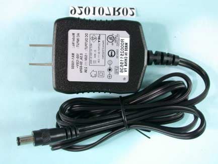
Click to zoom
Application Details
- Equipment Class
- DTS - Digital Transmission System
- Date of Grant
- Jul 28, 2003
- Application Purpose
- Original Equipment
- Date of Application
- Jul 27, 2003
- Equipment Note
- Bridge AP / Repeater AP
- Frequency Range
- 2412.00000000 - 2462.00000000
- Company
- Cellvision Systems Inc.
- Country
- Taiwan
Documents & Files
Document Text
Text extracted from the exhibit documents filed with the FCC. Open a document above to read the original.
Users Manual
Ethernet-to-Wireless Bridge User’s Manual Rev. 01 (April, 2003) Made In Taiwan RECYCLABLE - 2 - TABLE OF CONTENTS ABOUT THIS GUIDE.................................................................................................3 INTRODUCTION.......................................................................................................4 PACKAGE CONTENTS..............................................................................................5 GENERAL FEATURES...............................................................................................5 SERVICE FEATURES.................................................................................................6 EXTERNAL FEATURES.............................................................................................7 Front View............................................................................................................7 Rear View..............................................................................................................8 INSTALLATION........................................................................................................9 INSTALLING THE BRIDGE.......................................................................................9 CONNECTING THE BRIDGE...................................................................................10 Infrastructure Mode..........................................................................................10 Ad-Hoc Mode.....................................................................................................11 CONFIGURATION OF THE BRIDGE.......................................................................12 PRODUCT SPECIFICATIONS.............................................................................20 - 3 - ABOUT THIS GUIDE This manual describes the Ethernet-to-Wireless Bridge, including full descriptions of its features, detailed installation procedures, and product specification. - 4 - 1 INTRODUCTION Congratulations on purchasing your Ethernet-to-Wireless Bridge, a device that can be implemented in a variety of ways to provide wireless access by converting an Ethernet connection. For devices with a built-in Ethernet port, the Ethernet-to-Wireless Bridge provides a cost effective way to gain wireless connectivity, virtually transforming wired devices into wireless units! Connect any Ethernet-enabled device to an existing 802.11b wireless network using the Ethernet-to-Wireless Bridge. Typical applications include connecting a printer to a wireless network and connecting Ethernet-enabled devices such as game consoles or set top boxes to a Wireless Local Area Network (WLAN). Simply connect the Ethernet-to- Wireless Bridge to the Ethernet (RJ-45) port of a network device, such as a network storage device, Internet camera, network printer, network scanner, or other similar device. Using the Ethernet-to-Wireless Bridge allows the flexibility of placing network devices in remote locations while maintaining a high-speed connection. You can use the convenient Setup Wizard for the easy installation of your Ethernet-to-Wireless Bridge. Whether you are using it in Ad-Hoc mode or Infrastructure mode, you can begin with the Setup Wizard. Please refer to the Quick Installation Guide that is included with your purchase for instructions on how to use the Setup Wizard. - 5 - Package Contents Carefully remove all items from the package. In addition to this Hardware User’s Guide, be certain that you have: ♦ One Ethernet-to-Wireless Bridge ♦ One AC Power adapter suitable for your country’s electric power service ♦ One Installation CD-ROM ♦ One Quick Installation Guide If any item is missing, or if you find any damage or mismatch, promptly contact your dealer for assistance. General Features ♦ Transforms an Ethernet device into a wireless device ♦ Up to 22Mbps transfer rates ♦ Fully compatible with standard 802.11b-compliant devices ♦ Equipped with one 10/100 Ethernet port, Auto-MDI/MDIX ♦ Quick and Simple connectivity via Ethernet ♦ Supports Ad-Hoc or Infrastructure modes ♦ Easy web-based configuration when changing settings ♦ Encryption to provide a level of security for data transfers - 6 - Service Features With the Ethernet-to-Wireless Bridge, you can provide instant wireless access to the LAN (Local Area Network) for Ethernet-enabled devices. People use WLAN technology for many different purposes: ♦ Mobility - Productivity increases when people have access to data in any location within the operating range of the WLAN. Management decisions based on real-time information can significantly improve worker efficiency. ♦ Low Implementation Costs – WLANs are easy to set up, manage, change and relocate. Networks that frequently change, both physically and logically, can benefit from WLANs ease of implementation. WLANs can operate in locations where installation of wiring may be impractical. ♦ Installation and Network Expansion - Installing a WLAN system can be fast and easy and can eliminate the need to install cable through walls and ceilings. Wireless technology allows the network to go where wires cannot go - even outside the home or office. ♦ Inexpensive Solution – Wireless network devices are as competitively priced as conventional Ethernet network devices. ♦ Scalability - WLANs can be configured in a variety of ways to meet the needs of specific applications and installations. Configurations are easily changed and range from peer-to-peer networks suitable for a small number of users to full infrastructure networks of thousands of users that allow roaming over a broad area. - 7 - External Features This section describes the external features of your Ethernet-to-Wireless Bridge. Front View Front Panel There are two LEDs indicators on the front panel: LEDs Description Power A steady Green light indicates a proper connection to a power source. Wireless Link/Act A steady Yellow light indicates a wireless connection. A blinking light indi…
Text truncated - open the document above for the full version.
External Photos
Page 1 ANNEX PHOTOGRAPHS OF EUT Model: DWL-800AP+ Page 2 Page 3 Page 4 Model: DWL-810+ Page 5 Page 6 Page 7
ID Label/Location Info
Model No: WBA-200 FCC ID: QTRWBA10001 Tested To Comply With FCC Standards FOR HOME OR OFFICE USE 40mm 40mm
Internal Photos
Page 8 Page 9 Page 10 Page 11 Page 12
Operational Description
FCC ID: QTRWBA10001 ADT No.920619R04 Operational Description The transmitter of the EUT is powered by power adapter and connected with managing computer through RJ45 port. The antenna type is Dipole antenna without connector. Under normal use condition, the user has to keep at least 20cm separation distance between radiator and the body of the user. The other instruction, please have a look at the users manual. DSSS Information This device is Direct Sequence Spread Spectrum, the data is mixed by pseudorandom code which is an orthogonal code. The mixed data is digital modulated by BPSK and QPSK technique depends on the data rates. The CCK coding is applied for increasing the data rate, and also the processing gain will be increased. The bit rates are 1,2,5.5,11Mbps, the symbol rates are 1,1,1.375,1.375Mbps, the chip rates are always 11Mbps. So, the Chip/symbol is 11,11,8 and 8 respectively. Although is higher bit rate, the processing gain is lower than 10, but the CCK coding used in higher bit rate will provide 2.2dB coding gain.
RF Exposure Info
Report No: 920107R02A 1 FCC TEST REPORT REPORT NO.: RF92107R02A MODEL NO.: WBA-200 (Brand: Cellvision), WRA-200 (Brand: Cellvision) OEM MODEL NO.: CDINW00214 (Brand: CenDyne), CDINW00215 (Brand: CenDyne). ACCORDING: FCC Guidelines for Human Exposure IEEE C95.1 APPLICANT: Cellvision Systems Inc. ADDRESS: 18F-7, No. 79, Sec. 1, Hsin Taiwu Road, Hsichih, Taipei, Taiwan, R.O.C. ISSUED BY: Advance Data Technology Corporation LAB LOCATION: 47 14th Lin, Chiapau Tsun, Linko, Taipei, Taiwan, R.O.C. 0528 ILAC MRA Lab Code: 200102-0 Report No: 920107R02A 2 RF Exposure Measurement (Mobile Device) 1. Introduction In this document, we try to prove the safety of radiation harmfulness to the human body for our product. The limit for Maximum Permissible Exposure (MPE) specified in FCC 1.1310 is followed. The Gain of the antenna used in this product is measured in a Fully Anechoic Chamber (FAC) calibrated for antenna measurement in ADT, and also the maximum total power input to the antenna is measured. Through the Friis transmission formula and the maximum gain of the antenna, we can calculate the distance, away from the product, where the limit of MPE is reached. Although the Friis transmission formula is a far field assumption, the calculated result of that is an over-prediction for near field power density. We will take that as the worst case to specify the safety range. 2. RF Exposure Limit According to FCC 1.1310: The criteria listed in the following table shall be used to evaluate the environmental impact of human exposure to radio-frequency (RF) radiation as specified in 1.1307(b) LIMITS FOR MAXIMUM PERMISSIBLE EXPOSURE (MPE) Frequency Range (MHz) Electric Field Strength (V/m) Magnetic Field Strength (A/m) Power Density (mW/cm 2 ) Average Time (minutes) (A)Limits For Occupational / Control Exposures 300-1500......F/3006 1500-100,000......56 (B)Limits For General Population / Uncontrolled Exposure 300-1500......F/15006 1500-100,000......1.030 F = Frequency in MHz Report No: 920107R02A 3 3. Friis Formula Friis transmission formula : Pd = (Pout*G) / (4*pi*r 2 ) where Pd = power density in mW/cm 2 Pout = output power to antenna in mW G = gain of antenna in linear scale Pi = 3.1416 R = distance between observation point and center of the radiator in cm If we know the maximum Gain of the antenna and the total power input to the antenna, through the calculation, we will know the MPE value at distance 20cm. Ref. : David K. Cheng, Field and Wave Electromagnetics, Second Edition, Page 640, Eq. (11-133). 4 EUT Operating condition The software provided by Manufacturer enabled the EUT to transmit and receive data at lowest, middle and highest channel individually. 5. Classification This device is not fixed inside the host equipment, it is connected with host through wire. So it is easy to be re-located in the place where at least 20cm far away from the body of the user. Warning statement to the user for keeping at least 20cm or more separation distance with the antenna should be included in users manual. So, this device is classified as Mobile Device. Report No: 920107R02A 4 6 Test Results 6.1 Antenna Gain The maximum Gain measured in Fully Anechoic Chamber is 1.9dBi or 1.548(numeric). 6.2 Output Power Into Antenna & MPE value at distance 20cm: Channel Channel Frequency (MHz) Output Power to Antenna (mW) Power Density (mW/cm 2 ) Limit of Power Density (mW/cm 2 ) 1241248.3050.0101.0 6243748.0830.0101.0 11246250.4660.0101.0
Test Setup Photos
FCC ID: QTRWBA10001 Report No.: RF920107R02A 47 Issued: June 30, 2003 Reference No.: RF920107R02 5 PHOTOGRAPHS OF THE TEST CONFIGURATION CONDUCTED EMISSION TEST FCC ID: QTRWBA10001 Report No.: RF920107R02A 48 Issued: June 30, 2003 Reference No.: RF920107R02 RADIATED EMISSION TEST
Contact Information
Applicant
Celia Chu(Specialist)
Technical Contact
Advance Data Technology Corp.Ellis Wu
[email protected]+886-3-327-0910
13-1 Lane 19 WenShan 3rd St. · Taoyuan · Taiwan
Test Firm
Bureau Veritas CPS (H.K.) Ltd. Taoyuan BranchTommy Wu
Technical Specifications
| # | Rule Parts | Frequency Range | Power Output |
|---|---|---|---|
| 1 | 15C | 2.41 GHz - 2.46 GHz | 54.00 mW |
Other Applications from Cellvision Systems Inc.

QTRWLC10002
Nov 09, 2003Mini-ISA 2.4 GHz 802.11 Card
Equipment Class
DTS - Digital Transmission System
QTRPRS10001
May 26, 2003Print Server
Equipment Class
DTS - Digital Transmission System
QTRCAS10001
Mar 10, 2003Wireless Internet Camera
Equipment Class
DTS - Digital Transmission System