QUX-PC-800Panic Alert
Attenti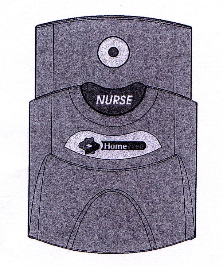
Click to zoom
Application Details
- Equipment Class
- DSC - Part 15 Security/Remote Control Transmitter
- Date of Grant
- Jun 19, 2003
- Application Purpose
- Original Equipment
- Date of Application
- Jun 19, 2003
- Equipment Note
- Panic Alert
- Frequency Range
- 318.00000000 - 318.00000000
- Company
- Attenti
- Country
- Israel
Documents & Files
Document Text
Text extracted from the exhibit documents filed with the FCC. Open a document above to read the original.
Users Manual
Pull Cord USER MANUAL FCC ID : QUX-PC-800 10 – June - 2003 HomeFree Systems Ltd Pendant (Panic Button) User Manual 1 Table of Contents 1. Foreword...................................................................................2 1.1. Pull Cord Device - State machine Drawing:..............................3 1.2. Activating the Pull Cord:...........................................................4 1.3. Activating a Panic Alert:............................................................4 1.4. Deactivating a Panic Alert:........................................................4 1.5. Deactivating the Pull Cord:........................................................5 1.6. Cleaning Instructions.................................................................5 2. FCC Notices..............................................................................6 HomeFree Systems Ltd Pendant (Panic Button) User Manual 1. Foreword The HomeFree at Care Centers system was designed to monitor special needs and Dementia individuals in the care center environment. The Pull Cord is one of the many unique elements of this system. The Pull Cord is a small wall-mounted device, to be installed at bedside and in the bathroom of nursing homes and assisted leaving homes. Once pulled, the Pull Cord Device shall transmit panic messages once every 18-22 seconds (random interval within this range), until it is reset by a nurse. It will be possible to turn the Pull Cord on and off (for saving battery life and for aviation safety while shipped). While the Pull Cord is ON, it shall transmit a status message, once every hour, to indicate that it is still functioning and to report its battery level. LED Indicator Pull Cord Button 2 HomeFree Systems Ltd Pendant (Panic Button) User Manual 3 1.1. Pull Cord Device - State machine Drawing: HomeFree Systems Ltd Pendant (Panic Button) User Manual 4 1.2. Activating the Pull Cord: The Pull Cord have an on/off function, to enable battery life saving while not in use, and aviation safety while being shipped. The Pull Cord is turned off by the manufacturer before shipment and must be activated before use. To activate, hold the Pull Cord insert the battery into the PCB. Once the Pull Cord is working, it sends a status message every 60sec to the monitoring station. The monitoring station then indicates the current battery status. This status message is sent until the Pull Cord is deactivated. 1.3. Activating a Panic Alert: To move from an ACTIVE – NO ALARM mode to an ACTIVE – PANIC ALARM mode – the user will have to pull the PCD cord. Once in panic alert mode, the Pull Cord sends a panic alert message to the monitoring station. This message is sent until the panic alert is deactivated. 1.4. Deactivating a Panic Alert: To move back from an ACTIVE – PANIC ALARM mode to an ACTIVE – NO ALARM mode (= Reset operation) – the user will have to move the pulled down knob to its original upper position. HomeFree Systems Ltd Pendant (Panic Button) User Manual 5 Even though the panic alert has been deactivated, the Pull Cord is still working. Therefore, the Pull Cord still sends a status message to the monitoring station. This status message is sent until the Pull Cord is deactivated. 1.5. Deactivating the Pull Cord: Holding the Pull Cord and take off the Battery. The Pull Cord is now in deactivated mode (turned off). 1.6. Cleaning Instructions A soft brush and any cleaning solution are all that is needed to clean the Pull Cord. Alcohol based solutions; Soapy water or Lysol can be used to clean the Pull Cord. HomeFree Systems Ltd Pendant (Panic Button) User Manual 6 2. FCC Notices This note is applicable to the American Pull Cord NOTE The Pull Cord complies with Part 15 of the FCC Rules. Operation is subject to the following two conditions: (1) This device may not cause harmful interference, and (2) This device must accept any interference received, including interference that may cause undesired operation. This device has been tested and found to comply with the limits of the Class B digital device, pursuant to Part 15 of the FCC rules. These limits are designed to provide reasonable protection against harmful interference in a residential installation. This device generates, uses and can radiate radio frequency energy and, if installed and used in accordance with the instruction, may cause harmful interference to radio communications. However, there is no guarantee that interference will not occur in a particular installation. If this device does cause harmful interference to radio or television reception, which can be determined by turning the equipment off and on, the user is encouraged to correct the interference by one or more of the following measures • Reorient or relocate the receiving antenna • Increase the separation between the equipment and the receiver. • Consult the dealer or an experienced radio/TV technician for help. CAUTION HomeFree Systems Ltd Pendant (Panic Button) User Manual 7 Any changes or modifications not expressly approved by the grantee of this device could void the user’s authority to operate the equipment. For Customer Support contact: Home Free Systems Inc. Wireless Tele home Care Solutions 6629 West Mill Road Milwaukee, WI 53218 USA Toll Free 1-800-606-0661 Fax +1-414-358-8100 Web: http://www.homefreesys.com
Block Diagram
Pull Cord Block Diagram Ant. RF Transmitter Unit Microcontroller Unit Led 14.7456MHz 3.6V Bat. Switch
Cover Letter(s)
TCB Confidentiality Form 10/06/2003 EMCCert DR. RAŠEK Boelwiese 5 91320 Ebermannstadt Germany Tel.: +49-9194-9331 Fax: +49-9194-7964-84 E-mail: [email protected] URL: http://www.emcc.de Gentlemen: This letter is to comply with Section 0.457(d)(2)(i) pertaining to confidential material. HomeFree would like the following document regarding this submission for FCC ID: QUX-PC-800 to be kept confidential. Schematics: 1 Page. The above material contains trade secrets or technical data, which would customarily be guarded from competitors. We do not want this document to be accessible to the general public. Sincerely, Gil Gemer VP R&D
ID Label/Location Info
Label Location QUX-PC-800
Operational Description
Pull Cord – PC-800 Operational description 1. General Description 1.1. The Pull Cord is a small wall-mounted device, to be installed at bedside and in the bathroom of nursing homes and assisted leaving homes. Once pulled, the Pull Cord Device shall transmit panic messages once every 18-22 seconds (random interval within this range), until it is reset by a nurse. It will be possible to turn the Pull Cord on and off (for saving battery life and for aviation safety while shipped). While the Pull Cord is ON, it shall transmit a status message, once every hour, to indicate that it is still functioning and to report its battery level. 1.2. The Pull Cord is a stand-alone unit. It is battery operated; it has RF transmitter module, a microcontroller, which controls the Pull Cord operation, and one PCB. 1.3. The Pull Cord has one RF channel. It is 318 MHz carrier with FSK modulated data. 2. Functional Description 2.1. The Pull Cord has four modes of operation. a) ACTIVATING THE PULL CORD: Three 5ms transmissions with interval 150 ms. b) ACTIVE: The Pull Cord sends a status message to the monitoring station (one 5ms transmission per hour) to indicate the current battery status. c) PANIC ALERT: The Pull Cord sends a panic alert message to the monitoring station in the following way. The first burst consists of three 5ms transmissions with 150ms interval (total burst duration 315 ms) and after that additional panic alert messages are sent, one 5ms alert message transmission once every randomly chosen interval of 18-22 s. This additional panic alert message is re-sent until the PANIC ALERT is deactivated. d) DEACTIVATION OF PANIC ALLERT: Three 5ms transmissions with interval 150 ms. after that the transmitter returns to ACTIVE mode. 5ms St ar t ad d i ti ona l Pa ni c A le r t 5ms 5ms 31 5m s 5ms 18- 22 s 18- 22 s 5m s Pa ni c al er t mo d e 15 0m s 5ms 5m s 5m s 315 ms 5ms 5ms 60 mi n Se nd ba tter y sta t us Se n d ba tt er y st at u s 60 mi n Ac t i vat in g t h Pe Ac t i ve mo de 150 m s 5m s 5m s 5m s 31 5m s 5m s 5ms 60 mi n Sen d ba tt er y sta tu s Se n d ba tte ry st at us 60 mi n D e act iv ati on th e Pa n ic a le rt Ac t iv e m o d e 150m s a ddi ti on a l Pa ni c A le rt e n d a n t Acti vati n g the Pull Cord Pull Cord time diagram
Test Report
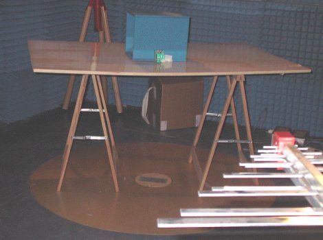
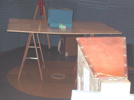
REV ∆ Description Sheet Effected Date Drawn Checked A 15.06.03 D.Lanuel S.Cohen EMC Laboratory FCCID :QUX-PC-800 Manufactured by HomeFree System Ltd. EMC Test Report According FCC Part 15 Requirements JUNE 2003 Function/Title Name Signature Date Prepared by Test Engineer D.Lanuel 15.06.03 Approved by EMC Lab. Manager S.Cohen 15.06.03 Pull Cord Unit EMI Test Report Table of Contents Para Page 1 TEST DATA INFORMATION...................................................................................................................4 A. DESCRIPTION OF EQUIPMENT UNDER TEST......................................................................................4 B. APPLICANT INFORMATION: ..........................................................................................................4 C. TEST PERFORMANCE: ..................................................................................................................4 2 TEST SUMMARY AND SIGNATURES.......................................................................................................5 A. TEST PERFORMED BY: ..................................................................................................................5 B. TEST REPORT PREPARED BY: ........................................................................................................5 C. TEST REPORT APPROVED BY:........................................................................................................5 3 GENERAL INFORMATION......................................................................................................................6 A. SPECIFICATION REFERENCE.........................................................................................................6 B. APPLICABLE DOCUMENTS.............................................................................................................6 4 ADMINISTRATIVE DATA.......................................................................................................................7 A. SCOPE......................................................................................................................................7 B. ADMINISTRATIVE DATA...............................................................................................................7 C. CERTIFICATION AND QUALIFICATIONS...........................................................................................7 D. MEASUREMENT REPEATABILITY INFORMATION.................................................................................7 E. MEASURING EQUIPMENT CALIBRATION..........................................................................................8 F. ANTENNAS CALIBRATION.................................................................................................................8 5 E.U.T INFORMATION............................................................................................................................8 A. E.U.T DESCRIPTION...................................................................................................................8 B. E.U.T TEST CONFIGURATION.......................................................................................................8 C. E.U.T MODE OF OPERATION DESCRIPTION.....................................................................................8 6 OUT OF BAND RADIATED FIELD STRENGTH TEST PROCEDURE..............................................................9 A. PRELIMINARY TEST SET UP...........................................................................................................9 B. PRELIMINARY TEST PROCEDURE.................................................................................................10 C. FINAL TEST SETUP.....................................................................................................................11 7 BANDWIDTH OF THE EMISSION PART 15.231—TEST RESULTS.............................................................12 A. GENERAL................................................................................................................................ 12 B. TEST RESULTS SUMMARY & CONCLUSIONS...................................................................................12 C. LIMITS OF FIELD STRENGTH FOR FUDAMENTAL ACCORDING 15.231..................................................12 D. TEST INSTRUMENTATION AND EQUIPMENT....................................................................................12 E. TEST RESULTS.........................................................................................................................12 8 FIELD STRENGTH OF FUNDAMENTAL PART 15.231-TEST RESULTS.......................................................13 A. GENERAL................................................................................................................................ 13 B. TEST RESULTS SUMMARY & CONCLUSIONS...................................................................................13 C. LIMITS OF FIELD STRENGTH FOR FIDAMENTAL ACCORDING 15.231..................................................13 D. TEST INSTRUMENTATION AND EQUIPMENT....................................................................................13 E. TEST RESULTS.........................................................................................................................14 9 RADIATED EMISSION PART 15.109-TEST RESULTS..............................................................................15 A. PRELIMINARY RADIATED EMISSION TEST RESULT ACCORDING PART 15.109.....................................15 B. GENERAL................................................................................................................................ 15 C. TEST RESULTS SUMMARY & CONCLUSIONS...................................................................................15 D. LIMITS OF RADIATED INTERFERENCE FIELD STRENGTH ACCORDING 15.109......................................15 E. TEST INSTRU…
Text truncated - open the document above for the full version.
Contact Information
Applicant
Stan DuPont(Electronic Engineer)
Test Firm
Elbit Systems Land C41Tadiran Ltd.Samuel Cohen
Technical Specifications
| # | Rule Parts | Frequency Range | Power Output |
|---|---|---|---|
| 1 | 15.231 | 318 MHz - 318 MHz | - |
Other Applications from Attenti
QUX-PC-840-2
Sep 12, 2012Pull Cord Station
Equipment Class
DXX - Part 15 Low Power Communication Device Transmitter
QUX-PC-840
Sep 11, 2012Pull Cord Station
Equipment Class
DSR - Part 15 Remote Control/Security Device Transceiver
QUX-URC-830-2
Sep 09, 2012Universal Receiver
Equipment Class
DSR - Part 15 Remote Control/Security Device Transceiver
QUX-NTT-830-2
Jul 29, 2012Nurse Tracking Tag
Equipment Class
DSC - Part 15 Security/Remote Control Transmitter
QUX-NTT-830
Jul 29, 2012Nurse Tracking Tag
Equipment Class
DSC - Part 15 Security/Remote Control Transmitter