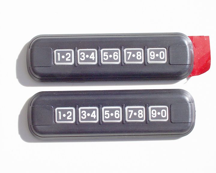
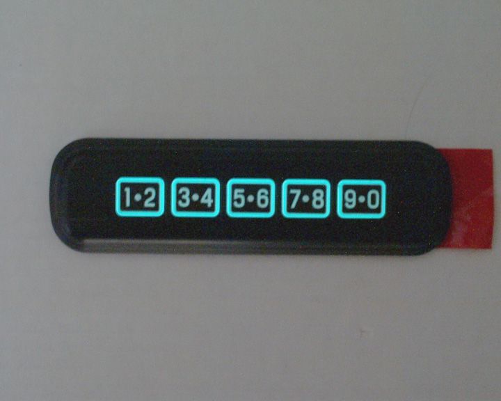
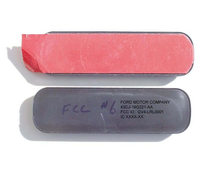
QV4-LRL0001Keypad Transmitter
Enterprise Electronics, L.L.C.
Click to zoom
Application Details
- Equipment Class
- DSC - Part 15 Security/Remote Control Transmitter
- Date of Grant
- Feb 12, 2003
- Application Purpose
- Original Equipment
- Date of Application
- Feb 12, 2003
- Equipment Note
- Keypad Transmitter
- Frequency Range
- 314.70000000 - 315.30000000
- Country
- United States
Documents & Files
Document Text
Text extracted from the exhibit documents filed with the FCC. Open a document above to read the original.
Users Manual
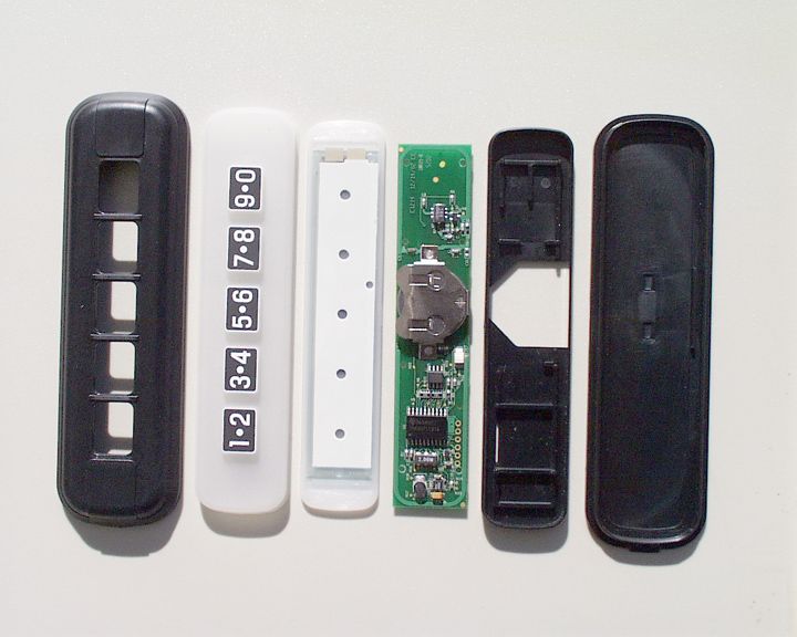
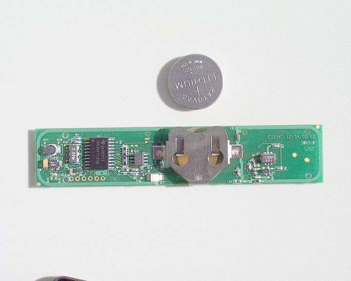
Locks and Security KEYLESS ENTRY SYSTEM If there is any potential keyless entry problem with your vehicle, ensure ALL key fobs (remote entry transmitters) are brought to the dealership, to aid in troubleshooting. Your vehicle is equipped with a keyless entry keypad, you can: • lock or unlock the vehicle doors without using the key. Your vehicle has a factory-set 5 digit code that operates the keyless entry system. You can also program your own 5 digit personal entry code. The factory-set code is located: • on the owner’s wallet card in the glove compartment • or at your dealer. When pressing the controls on the keyless entry keypad, press the middle of the controls to ensure a good activation. Programming your own personal entry code To program your own code: 1. Enter factory set code. 1 - 2 3 - 4 5 - 6 7 - 8 9 - 0 2. Press 1/2 control within five seconds of step 1. 3. Enter your personal 5 digit code. Enter each digit within five seconds of previous one. Do not set a code that includes five of the same number or presents them in sequential order. Thieves can easily figure out these types of codes. Your personal code does not replace the permanent code that the dealership gave you. You can use either code to unlock your Locks and Security vehicle. If a second personal code is entered, the module will erase it in favor of the new code. If you wish to erase your personal code, use the following instructions: 1. Enter factory set code. 2. Press 1/2 control within five seconds of step one. 3. Press 7/8 control and 9/0 control at the same time within five seconds of step 2. 1 - 2 3 - 4 5 - 6 7 - 8 9 - 0 The system will now only respond to the factory set code. Anti-Scan Feature 1 - 2 3 - 4 The keyless entry pad is disabled for 1 minute after 7 unsuccessful attempts at entering a valid key code. The keypad will flash during this 1 minute mode. However, the 7/8 and 9/0 cont 5 - 6 7 - 8 9 - 0 rols will still one minute of keypad inactivity lock the vehicle. Anti-scan will turn off after: • Locks and Security Unlocking the doors with the keyless entry system To unlock the driver door, enter either the factory set code or the personal code (each digit must be pressed within five seconds of the prior digit). 1 - 2 3 - 4 5 - 6 7 - 8 9 - 0 To unlock all doors, enter the factory set code or personal code (driver door unlocks) and press the 3/4 control within five seconds. Locking the doors with the keyless entry system It is not necessary to enter the factory or personal code prior to locking all doors. To lock the doors: 1 - 2 3 - 4 5 - 6 7 - 8 9 - 0 • Press the 7/8 control and the 9/0 control at the same time. Replacing the batteries One coin type three-volt lithium battery BR2335 (Ford Part # XXXX-XXXXX-AA) powers the keyless entry keypad. This battery must be purchased through a Ford or Lincoln/Mercury dealer parts and service department. Low Battery Warning: When the batteries of the Keyless Entry Keypad are running low and need to be changed, the vehicle will give you a warning. After entering your factory set or personal entry code in the keypad, instead of unlocking the driver’s door, the vehicle will unlock the driver’s door, lock it, and then unlock it again. Locks and Security To replace the batteries: 1. Take a regular flat head screwdriver with a ¼” wide head and insert it into the slot on the right side of the keypad. Gently twist the screwdriver to pry off the top cover. Pull cover off by pulling to the left and then up. The top cover and the guts of the keypad will come off the vehicle and the back cover will remain mounted to the vehicle. 2. Remove guts of keypad from top cover and place the top cover on a soft surface to avoid scratching the decorative finish. Be careful not to remove the silicone rubber membrane from the rest of the electronics. 3. Take same regular flat head screwdriver with a ¼” wide head and insert it into one of the two slots on the metal battery holder. The two slots are on either side of the (+) sign of the battery holder. The battery will then slide out enough to grab with your fingers. 4. Pull the old battery from the unit and replace with the new battery. Be sure that the battery is seated completely in side the battery holder. 5. Replace the keypad guts back inside the top cover, making sure the screwdriver slot is located next to the 9/0 key. 6. Hold the top cover and the keypad guts together, align the unit with the back cover mounted on the vehicle, and gently press the two pieced together. Gently run your finger around the perimeter of the keypad to assure it is properly seated. 7. Press the 7/9 key simultaneously to lock the vehicle and to verify that the unit is now functioning again. Locks and Security Replacement of the battery will not cause the keypad to become deprogrammed from your vehicle. The keypad should operate normally after battery replacement. Replacing stolen/damaged keyless entry keypad If a the keyless entry keypad has been stolen or damaged, or if you would like to purchase an additional keypad for your passengers door and have it programmed to your vehicle: • Take your vehicle as well as all your keyfob remote transmitters to your dealer, or • Perform the programming procedure yourself Programming keyless entry keypads It is necessary to have all (maximum of four – original and/or new) keypads and remote transmitters available prior to beginning this procedure. To program the keyless entry keypad yourself: 3 4 5 2 1 3 4 5 2 1 • Place the key in the ignition and turn from 2 (LOCK) to 3 (OFF) and cycle between 3 (OFF) and 4 (ON) eight times in rapid succession (within 10 seconds) with the eighth turn ending in the 4 (ON) position. The doors will lock/unlock to confirm that programming mode has been entered. • Within 20 seconds, program the keyless entry keypad by entering in the factory-set or personal code (if already programmed into keypad). The doors will lock/unlock to confirm that the keypad has been programmed. (If more than 20…
Text truncated - open the document above for the full version.
Block Diagram
3VOLT POWER BR2335 LITHIUM COIN CELL 5 KEY KEYPAD MSP430F1121 LOW POWER MICROCONTROLLER 2.00 MHz CLOCK DERIVED FROM RESONATOR NORMAL MODE - SLEEP ALL CLOCKS OFF ACTIVE ON KEYPAD CLOSURE 2.00 MHz CLOCK ACTIVE ON AVERAGE 4 MINUTES PER DAY MODIFIED COLPITTS SAW OSCILATOR 315 MHz MANCHESTER ENCODED BI-PHASE ON-OFF KEYING MODULATION 250 uSEC PULSE WIDTH 48.6 mSEC PACKET LENGTH 2.0MHz 1.5p-p ANTENNA EL PANEL CONTROL 2.00 MHz CERAMIC RESONATOR ELECTROLUMINESCENT PANEL DRIVER U2 - D356A 50KHz FLYBACK CONVERTER 110 VOLT DC Co: Title: Board: Author: Date: ENTERPRISE ELECTRONICS COMBINATION RKE CLOCKS E20503BD.SCH D. Pearson 2/05/03 100 Hz 110 Volt P-P AC COUPLED MODIFIED SINE WAVE 110VAC 100 HZ ELECTROLUMINESCENT PANEL Revision: Size: Sheet 1 A of A 1
Operational Description
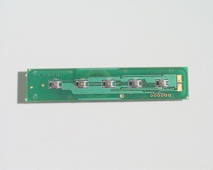
THEORY OF OPERATION FOR COMBINATION KEYLESS ENTRY E20503A The Keyless Entry system consists of nine functional groups: keypad input, reset circuit, microcontroller, non-volatile memory, ambient light sensor, low battery detect, electro- luminescent driver, 315 MHz transmitter and power conditioning. KEYPAD INPUT CIRCUITRY Five SPST momentary switches SW1- SW5 are connect to ground on one side and input pins on the (U1) MSP430 microcontroller on the other. These pins are held a positive logic level, 1.8 to 3 volts by a 10K ohm resistor RN2 and RN1. When a switch is closed the input pin of the MSP430 is taken to ground giving a logic zero state. This transition is sensed by the MSP430 (U1), which will wake up from its normal sleep mode and read which switch was pressed. RESET CIRCUIT Two of the keys SW4 and SW5 are also connected to an OR gate U5, which operates as a negative logic AND gate. Closure of both these keys simultaneously pulls the output of U5 low, which causes C12 to start charging. This is seen as a low pulse at the U1 reset line. This low pulse resets the microcontroller U1 clearing any lockup conditions in the microcontroller. Upon reset the microcontroller will look at the state of SW4 and SW5 and if both are logic zero will send a lock command via the transmitter. This circuit provides fail-safe operation for the important LOCK command. MICROCONTROLLER The MSP430F1121 (U1) is the heart of the system. All inputs are sent to it and all outputs come from it. It normally is in a sleep state with all clocks stopped. Depression of any key will bring it into an active state for at least five seconds. A simultaneous closure of SW4 and SW5 will reset U1 and immediately send the lock command followed by transition into sleep mode. When active U1 uses X1 to generate a 2.00 MHz clock for internal operation. This in not active in sleep mode. When any of the supporting circuits require it, U1 will source 3 volts to the power inputs for the non- volatile memory, ambient light sensor, and low battery detect. This power switching reduces the quiescent current of the system. The pull-down resistor R1 keeps the TST input low as required for normal operation. Capacitor C1 and C4 provide decoupling at high switching frequencies to maintain a clean power source to U1. NON-VOLATILE MEMORY U3 a IIC bussed Electrically Erasable Programmable Read Only Memory (EEPROM) stores the rolling code counter, and the user programmable entry code. Two resistors in RN2 provide pull-ups to logic 1 for proper operation of the IIC bus. Both the clock line and the data are driven by U1 when rolling code writes and reads are done. AMBIENT LIGHT SENSOR Q1 a phototransistor and R2 form a high sensitivity light sensor. With no illumination, the output is held near ground. As the illumination increases the output signal increases toward 3 volts. This sensor output is connected to the analog comparator input on the microcontroller U1. If this level is greater than the internal reference level of the comparator, the comparator signals the microcontroller that the ambient light level is high. The Electro-luminescent panel is NOT energized for this condition. LOW BATTERY DETECT The internal analog comparator is setup using the internal diode as the reference. Power to the resistor R3 is applied by the microcontroller. The time required for the voltage on the capacitor C3 to reach the reference voltage of the internal diode is measured. This time is proportional to the battery voltage. A time lookup table equates time to battery voltage. If the battery voltage is below 1.8 volts and indication is given by a flashing the electro luminescent panel. ELECTRO LUMINESCENT PANEL CIRCUIT A 100 Hz 110v p-p AC signal is applied to the Electroluminesecnt (EL) panel connected at P1. One side is grounded is other is at 110 v p-p AC 100 Hz. This causes the EL panel to glow bluish-green when commanded by the microcontroller U1. EL panel drive is developed by U2 using an internal 50 KHz oscillator feeding inductor L1 in a flyback configuration. This develops a high DC voltage that is chopped by an internal oscillator running at 110 Hz. This frequency is determined by capacitor C10. Capacitor C16 prevents high frequency RF from entering U2. Capacitors C11 and C9 provide high and low frequency decoupling to provide a low impedance power source for U2. 315 MHz TRANSMITTER Transistor Q2 forms a SAW controlled Colpitts oscillator. Resistors R6 and R7 determine Q2’s bias point. C15 and L2 form a resonant collector load. While C13 decouples the power feed at high frequencies. Capacitors C7 and C5 form a divider that controls oscillator startup and also add to the resonant frequency of C15 and L2. SAW resonator X2 provides the high Q frequency control element that determines the oscillators frequency. Capacitor C8 prevents RF from reaching the microcontroller U1 by shunting RF energy to ground. C14 along with the printed circuit trace between C14 and the collector of Q2 form a 2nd harmonic trap that reduces the 2nd harmonic (630 MHz). D. Pearson 2/09/03
Schematics
1 2 4 1 2 1 2 3 4 8 7 6 5 8 7 6 5 M24C01-SMN3 U3 1 2 3 4 10 1 2 3 4 5 6 7 8 9 20 19 18 17 16 15 14 13 12 11 + - GND L- VOUT L+ E EL2 EL1 V+ TEST VCC P2.5/Rosc VSS XOUT XIN /RST/NMI P2.0/ACLK P2.1/INCLK P2.2/CAOUT/TA0 P1.7/TA2/TDO/I P1.6/TA1/TDI P1.5/TA0/TMS P1.4/SMCLK/TCK P1.3/TA2 P1.2/TA1 P1.1/TA0 P1.0/TACLK P2.4/CA1/TA2 P2.3/CA0/TA1 K5 RST K5 K4 K3 K2 K1 K3 K4 RST TST S W 1 1/2 S W 2 3/4 S W 3 5/6 S W 4 7/8 S W 5 9/0 N22 C8 33pF R6 24Kê C14 3.0pF C15 5.6pF L2 39nH C13 100pF N9 C7 6.0pF N8 C5 15pF R7 82 N7 315MHz X2 Q2 PBR941 3V U5 NC7SP32 3V R2 1M N12 Q1 SFH3211 N18 L1 10mH N17 P1 X1 2MHz N20 N19 10K RN2 R1 10K TP5 TST C4 .1uF TP2 TX- TP3 TX+ N16 TP1 RST N14 C10 .01uF N15 C16 100pF 3V C9 10uF 6.3V C11 .01uF U2 D356A N4 C12 .01uF VCC WP' SCK SDAGND A0 A1 A2 N11 R3 100K N13 C3 .1uF MSP430F1121PWU1 N10 N5 N6 N21 N2 N1N3 C1 .1uF B 1 B R 2 3 3 5 A E T R 3V TP6 TXD TP4 RXD 10K RN1 TRACE ANTENNA *2 *1 *5 *3 Co: Title: Board: Author: Date: NOTE1 : C14 on PCB, 3.0pF NOTE2 : R6 was 18K, now 24K NOTE3 : C7 was 5.6pF now 6.0pF NOTE4 : C16 100pF added at U2 NOTE5 : Q2 changed to PBR941 NOT USED C2, C6, R4, R5, U4 Last used C16, L2, N22, Q2, R7, SW5, U5 ENTERPRISE ELECTRONICS Combination RKE E20503A.SCH D. Pearson 2/05/03 TP5, X2 Revision: Size: Sheet 1 A *4 of B 1
Test Report
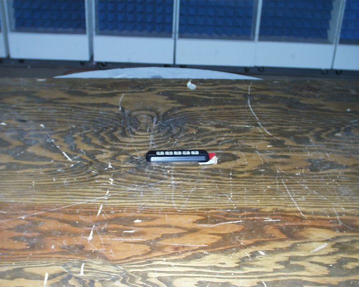
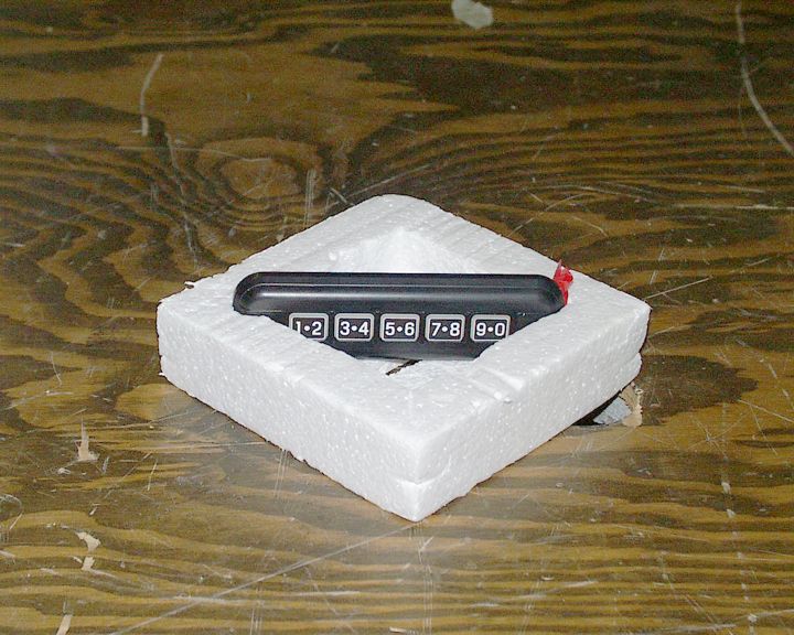
QV4-LRL0001 ENTERPRISE ELECTRONICS Test Report of an Intentional Radiator for Certification under Part 15 of the FCC rules DUT: Wireless keypad FCC ID QV4-LRL0001 Model LRL0001 Date: 4-Feb-2003 Manufacturer: Enterprise Electronics, L.L.C. 2120 Austin Drive Rochester Hills, MI 48309 (248) 844-1410 Prepared by: Control Design & Testing, Inc. 6010 Red Fox Drive Spotsylvania, VA 22553 (540) 582-2826 1 QV4-LRL0001 ENTERPRISE ELECTRONICS A. DEVICE UNDER TEST The product is a transmitter used as keyless access control device for automobiles. This device is similar in function to the popular keyfob transmitters currently offered by Ford Motor Company and works in conjunction with their existing keyless entry receivers. This product is designed to operate under the provisions of Part 15.231 of the FCC rules and RSS-210 in Canada. The frequency of operation is 315.00 MHz. nominal. The modulation mode is on/off keying using a proprietary Manchester phase format. In normal operation, this device is programmed to transmit 6 data packets for each activation and ceases transmission within 650ms. of activation The device is powered by an internal BR-2335 size 3 volt lithium coin cell battery. The rf circuit is a modified colpitts oscillator using a SAW resonator as the frequency determining element. The radiating element is a track antenna printed on the circuit board. . There is no provision to connect an external antenna. The test sample is in a plastic prototype enclosure. The FCC ID will be embossed in the plastic but for beta units a label will be attached as a temporary measure. B. MEASUREMENT PROCEDURE: RADIATED EMISSIONS Radiated emissions testing of this device was conducted at the Carl T. Jones test facility located in Springfield, Virginia. FCC Site #90490 The field strength measurements were conducted according to the procedures set forth in ANSI C63.4 (1992). The device under test was placed on a rotating turntable 0.8 meters high, centered at 3 meters distant from the measurement antenna. The device was placed in the center of the turntable and tested in three positions as shown in the test setup photographs. For the purpose of radiated emissions testing, the test sample was specially programmed to continuously transmit a “lock” command signal. The occupied bandwidth (Plot 1) was captured using this signal. 2 QV4-LRL0001 ENTERPRISE ELECTRONICS Plot 1 3 QV4-LRL0001 ENTERPRISE ELECTRONICS The field strength measurements were taken using an HP8596E spectrum analyzer, an EMCO 3121C dipole set, an EMCO 3115 double ridge guide horn and an Avantek UJ210 preamp. The device was scanned from 30 MHz. to 5 GHz. and all emissions were noted. In this case, the only emissions detected were those harmonically related to the fundamental transmit frequency. At each detected emission frequency, the device was measured by rotating the turntable and adjusting the antenna height over a range of 1 to 4 meters to obtain the maximum output level. This procedure was performed with both horizontal and vertical antenna polarizations for each of the test positions shown in the test setup photos. The peak reading for each frequency was recorded in the fourth column in Table 1 below. Measurements taken for weak emissions were performed by reducing the distance from the measurement antenna to 1 meter and factoring –9.54dB into the calculation. This method was used for the 10 th harmonic. ENTERPRISE ELECTRONICS, LLCFCC ID: QV4-LRL0001 EUT: KEYPAD TRANSMITTER PART 15.231, 15.35DATE: 04-FEB-03 Ant. Polar. H/V 314.967H20.3-39.9112.92341553036041 629.934H26.7-71.8712.91235280604 944.901V30.9-76.5612.91167264604 1259.868V27.6-89.9812.917039604 1574.835V28.8-79.8012.9631143500 1889.802V30.4-87.0212.933075604 2204.769V31.1-87.5112.933877500 2519.736H32.2-89.0312.932273604 2834.703H34.1-81.7612.9927210500 3149.669H35.4-89.1212.9461104604 Table 1 RADIATED EMISSIONS DATA Frequency In MHz. Peak Power uV/m@3m Peak reading dBm Ant. Factor dB ANTENNA: DIPOLES/DRG HORN Duty Cycle -dB FCC Limit uV/m@3m Corrected Power uV/m@3m 4 QV4-LRL0001 ENTERPRISE ELECTRONICS C. DUTY CYCLE AND INTERVAL CALCULATIONS The occupied bandwidth and duty cycle measurements were made using an HP8594E spectrum analyzer and plotted with an HP7475A pen plotter. The computation for the duty cycle correction factor in column five in Table 1 is derived from the manufacture’s description of the data scheme and is verified by plots 2 through 7. Plot 2 5 QV4-LRL0001 ENTERPRISE ELECTRONICS Plot 3 The code format for this device is a 50% Manchester phase pulse position scheme that comprises 90 bit frames of 500μs. each, divided into preamble and data, separated by a 3.5ms. space. The entire packet length including preamble is 48.5 ms. and is repeated a 100ms. intervals. Measurements of pulse widths have been taken at points at least 6dB below peak to insure worst case. The correction factor is given by: 20log(total on time in ms/100ms.) = -X dB. 6 QV4-LRL0001 ENTERPRISE ELECTRONICS 90 bits * 500us. * 0.5 = 22.5ms. 20log(22.5ms./100ms.) = -12.956 dB. As provided in Part 15.35 of the FCC rules, a correction factor of –12.9 dB is used for the calculations on the data sheet. Plot 4 7 QV4-LRL0001 ENTERPRISE ELECTRONICS Plot 5 8 QV4-LRL0001 ENTERPRISE ELECTRONICS Plot 6 9 QV4-LRL0001 ENTERPRISE ELECTRONICS 10 Plot 7
Contact Information
Applicant
David J. Pearson(President)
Test Firm
Carl T. Jones CorporationCarl Jones
Technical Specifications
| # | Rule Parts | Frequency Range | Power Output |
|---|---|---|---|
| 1 | 15.231 | 314.7 MHz - 315.3 MHz | - |
Other Applications from Enterprise Electronics, L.L.C.

QV4-315
Apr 16, 2024315 MHz Keypad
Equipment Class
DSC - Part 15 Security/Remote Control Transmitter
QV4-LRL053
Jul 18, 2013RF KEYPAD
Equipment Class
DSC - Part 15 Security/Remote Control Transmitter
QV4-LRL0006
Aug 07, 2007KEYPAD TRANSMITTER
Equipment Class
DSC - Part 15 Security/Remote Control Transmitter
QV4-LRL0005
Nov 14, 2006KEYLESS ENTRY PAD
Equipment Class
DSC - Part 15 Security/Remote Control Transmitter
QV4-LRL0004
Dec 28, 2005Keypad Transmitter
Equipment Class
DSC - Part 15 Security/Remote Control Transmitter