QW3-BT112FTT06BLUETOOTH FLASH DISK
Formosa Teletek Corporation
Click to zoom
Application Details
- Equipment Class
- DSS - Part 15 Spread Spectrum Transmitter
- Date of Grant
- Jul 16, 2003
- Application Purpose
- Original Equipment
- Date of Application
- Jul 16, 2003
- Equipment Note
- BLUETOOTH FLASH DISK
- Frequency Range
- 2402.00000000 - 2480.00000000
- Company
- Formosa Teletek Corporation
- Country
- Taiwan
Documents & Files
Document Text
Text extracted from the exhibit documents filed with the FCC. Open a document above to read the original.
Users Manual
Formosa Teletek Corporation BTW User’s Guide Version: 1.3 Formosa Teletek Corporation 358, Huaya 2nd Rd., Gueishan Shiang, Taoyuan, Taiwan Tel: 886-3-3280800 Fax: 886-3-3281231 Software & Driver Installation(98/ME/2000/XP) 1. Close any open programs and insert the utility CD into your CD-ROM Driver. 2. Click on the My Computer icon on your desktop. (a) Click on the icon representing your CD-ROM to open it. (b) Double click on the “SETUP” icon. 3. The Welcome screen informs you that the WIDCOMM Bluetooth Software Setup program is ready to begin. Click on the “Next” button. 4. I n the License Agreement screen, click on the radio button to the left of ”I accept the terms in the license agreement”. Click on the ”Next” button. 5. In the Destination Folder screen you are asked to confirm the application software. If you would like, you may change the destination folder to another location as the directory. Click on the ”Next” button. 6. The Ready to install the Program screen informs you that the driver is ready for installation. Click on the “Install” button to continue. Note: Please click on “OK” button from the Driver Signature Notice dialog box to proceed with driver installation in Win2000 and WinXP operating system. 7. After you click “OK” button from the Driver Signature Notice dialog box at previous step, the InstallShield Wizard will continue to install WIDCOMM Bluetooth Software. 8. When the files have been copied, you will be presented with a screen informing of its completion. Click on the ”Finish” button, a pop-up dialog box will on the screen. 9. After you click on the ”Finish” button, the FORMOSA TELETEK USB DONGLE Driver will finish installation and the ”Bluetooth Icon” resides in the Windows system tray. 10. Double click the ”Bluetooth Icon” resides in the Windows system tray or on the Desktop to perform some initial setup. Click on the check button you want the Bluetooth feature on your computer. Then click on the ”Next” button. 11. Enter a unique name for this computer, and select a computer type from the drop-down menu. Click on the ”Next” button. 12. Click on the ”Next” button to configure the Bluetooth services. 13. Enable a service, place a check in the box next to the service name. Click on the ”Next” button. 14. Click on the ”Next” button to configure the way this computer will use its services. Otherwise click on the “Skip” button. 15. Click on the ”Finish” button, Initial Bluetooth Configuration Wizard will finish. Notice: The changes or modifications not expressly approved by the party responsible for compliance could void the user’s authority to operate the equipment. User Information This device complies with part 15 of FCC Rules. Operation is subject to the following two conditions: (1) This device may not cause harmful interference, and (2) This device must accept any interference received, including interference that may cause undesired operation. The FCC require the user to be notified that any changes or modification made to this device that are not expressly approved by FORMOSA TELETEK CORPORATION may void the user’s authority to operate the equipment.
Block Diagram
Function Block Diagram Antenna 12MHz Crystal USB Hub Flash Disk Controller 6MHz Crystal 14.318MHz Crystal Flash Memory USB Connector Baseband Synthesizer Digital Smart Radio TX/RX SW
External Photos
External Photos
ID Label/Location Info
Label Sample Made in Taiwan ID: QW3-BT112FTT06 30mm 10mm
Internal Photos
Internal Photos
Operational Description
Description of Operation Principle This device is connected to PC or other host devices through a USB hub device connecting to the USB connector on one side, and propagates microwave signals from the antenna on the other side. The microwave signals in the air are received by the antenna of the receiver, through Tx/Rx switch which is controlled by the transceiver, then mixed with the 12MHz signals generated by the crystal, and down convert to frequency of base-band. The signals from the transceiver finally transfer to USB signals through base-band controller and exchange data with PC or other host devices. Furthermore, the USB hub device on the BT112FTT06 also controls access of the flash memory. The flash disk controller device use one port of the USB hub device of BT112FTT06 and is used to perform the directive from PC or other USB host devices to access the data in the flash memory. utilize a 6 MHz crystal input. Connect the crystal as shown in Figure 6. An internal PLL then generates the 48 MHz clock used to sample data from the upstream port and to synchronize the 12 MHz used for the USB clock. USB???????????????????: ????????????, USB ??????????, PCB ?????????????? ???????,??????????????USB?????USB?????????????,? ?????????????,???????????????????????????? USB?????????????????:USB???????FLASH(???????)? PCB?????,USB???????????????????:1?USB??????????; 2??????????????????;3?FLASH??????????????????,????? ?,??????????;4?PCB??????????????????????????????? ?,USB???????????????????????????USB??????????????? ???,??????????????????????????? ???FLASH: ?????FLASH????USB??????????????????,??90%??, ?????????????????: 1. ???? ??????????????,?3S?CYPRESS?OTI?PROLIFIC?ST? ??OTI?PROLIFIC?3S????????????????? 1.?OTI????,???????????OTI006808,??OTI??????,??? ????OTI006803????,????????????Bug,???6803????????? ????????,???????????????????,??????????????,?? ??????????????????,??,???????OTI??????????????? ?????????? 2.PROLIFIC?????????,????????????????????,????? ????????PL2315? 3.SSS?????,??????USB1.1 UHCI/OHCI?????????????,?? ??????600KB,??920KB,??USB FDD/HDD/ZIP????,???????? 3s6633B1?3s6633B2. ????????,???????????:OTI??2?0??;3S??1?3??; PROLIFIC(PL)??1?5??;????,OTI???????,????????????? ??????????OTI006808?????? 2. FLASH?? ??????FLASH???????????????????????,FLASH??USB ???????????,??????????????????FLASH?????????? FLASH????????Sumsung?Toshiba??????????????????,??? Flash????????????,????????? ????FLASH?????????????: SAMSUNG K9F2808XXX 16MB/PCS SAMSUNG K9F5608XXX 32MB/PCS SAMSUNG K9F1208XXX 64MB/PCS SAMSUNG K9K1G08XXX 128MB/PCS ????????FLASH???,???????????????????????,??? ????128MUSB????????,?????64MFLASH??,??????32M? FLASH??,???????????????????27-30???????FLASH???.? ??????FLASH,???????FLASH????????FLASH???????,??? ???????? ??????????????128M?????64M???????????? FLASH?????USB????????????????????????U???????? ?,??????????????,????FLASH????????????. PCB?????: PCB ???????????????????????????????? PCB ?????? ??????????????????,????????“??“????????????FLASH ???????????? ??USB?????????PCB??????,???????????????????? ??????,????????????????????????????????????,?? ????????????,????????????????,???????????????? ?????? U??????:??????U??????????,????????,?????????? ?.?????????.????????????????????????,,??????.???? ???????.??????????,????????????.??????????U???? ??.
Schematics
1 2 3 4 5 6 78 ABCD 8 7 6 5 4 3 2 1 D CBA Title Number Revision Size A2 Date: 26-Jun-2003 Sheet of File: d:\My Documents\Product Data\FLASH\BT112FTT06 one flash\PROJ\BT1112FTT06.Ddb Drawn By: SD1SD0SD2SD3SD7SD6SD4SD5RB CE2CE3 CLEALEWE Y1 14.318MHz R361M C3120pF C3020pF C260.1uF CE1CE0 C250.1uF L810nHL710nH R141.5K R281K XTAL1XTAL2 R35100K /RESET 1 GND 2 VCC 3 U10G688 3.3V 3.3V N/C 1 N/C 2 N/C 3 N/C 4 N/C 5 SE 6 R/B 7 RE 8 CE 9 N/C 10 N/C 11 VDD 12 VSS 13 N/C 14 N/C 15 CLE 16 ALE 17 WE 18 WP 19 N/C 20 N/C 21 N/C 22 N/C 23 N/C 24 N/C 25 N/C 26 N/C 27 N/C 28 I/O0 29 I/O1 30 I/O2 31 I/O3 32 N/C 33 N/C 34 N/C 35 VSS 36 VDD 37 N/C 38 N/C 39 N/C 40 I/O4 41 I/O5 42 I/O6 43 I/O7 44 N/C 45 N/C 46 N/C 47 N/C 48 U7 FLASH SD7SD6SD5SD4SD3SD2SD1SD0 WPWEALECLE RBRECE0 RESETF1_WP RESETF_USB_D+F_USB_D- GPIO_pad 1 LED_OUT_pad 2 F1_R_B_pad 3 F1_WE_pad 4 F1_RE_pad 5 F1_IO_pad[7] 6 F1_IO_pad[6] 7 F1_IO_pad[5] 8 F1_IO_pad[4] 9 F1_IO_pad[3] 10 F1_IO_pad[2] 11 F1_IO_pad[1] 12 F1_IO_pad[0] 13 F1_CLE_pad 14 F1_ALE_pad 15 Sel_reset_pad 16 Reset_B_pad 17 F1_WP_pad 18 XTAL2 19 XTAL1 20 VDD0 21 VSS0 22 VDD5_0 23 VDD5_1 24 VSS1 25 VDD1 26 DPLS_IO 27 DMNS_IO 28 F1_CE0_pad 29 F1_CE1_pad 30 F1_CE2_pad 31 F1_CE3_pad 32 U11OTi 6828 L510nH C171uF Y2 6MHz C327pF C1427pF R21.5K R3424 R3324 R323.9 R31 3.9 R61.5k DP0 1 DM0 2 Vcc 3 /RESET 4 EECLK 5 EEDATA/CANGED 6 GND 7 BUSPWR 8 /PWRON1 9 /OVRCUR1 10 DM1 11 DP1 12 /PWRON2 13 /OVRCUR2 14 DM2 15 DP2 16 /PWRON3 17 /OVRCUR3 18 DM3 19 DP3 20 /PWRON4 21 /OVRCUR4 22 DM4 23 DP4 24 VCC 25 /EXTMEM 26 TEPLL/48MCLK 27 GND 28 XTAL2 29 XTAL1 30 TSTMODE 31 SUSPND 32 U9TUSB2046B R1715k R1615k R1915k R2215k 5V 1 D- 2 D+ 3 GND 4 05 J1USB-PROT RESET B_USB_D+B_USB_D-USB_D+F_USB_D+F_USB_D- WP C280.1uF C270.1uF C240.1uF F1_WPRE 3.3V 3.3V 3.3V 3.3V 3.3V 3.3V 3.3V 5V 5V USB_D+ 5V L410nH C230.1uF C200.01uF 2.8V IN 1 GND 2 /SHDN 3 OUT 5 BP 4 U8CM2381/2/3/N C294.7 μF 3.3V B_USB_D+B_USB_D- C18 0.01uF 2.8V C190.01uF NC A1 NC A2 NC A3 NC A4 NC A5 NC A6 NC A7 NC A8 PI1_RFCE_TP A9 NC B1 NC B2 RF_GND B3 RF_GND B4 RF_GND B5 RF_GND B6 RF_GND B7 RF_GND B8 CLK_12_MHZ+ B9 NC C1 NC C2 RF_GND C3 RF_GND C4 RF_GND C5 RF_GND C6 RF_GND C7 RF_GND C8 TX_RX_DATA C9 UART_RX C10 UART_RTS C11 AAI_SFS C12 AAI_SCLK C13 NC C14 NC D1 NC D2 RF_GND D3 RF_GND D4 RF_GND D5 RF_GND D6 RF_GND D7 RF_GND D8 CCB_DATA D9 UART_TX D10 UART_CTS D11 RESET_BB D12 DIG_GND_1 D13 NC D14 NC E1 NC E2 RF_GND E3 RF_GND E4 RF_GND E5 RF_GND E6 NC J3 NC J4 NC J5 NC J6 NC J7 NC J8 NC J10 NC J11 NC J12 CCB_Latch J13 PH0_TP6 J14 RF_GND E7 RF_GND E8 LSTAT_0 E9 ENV0 E10 J_RDY E11 USB_D+ E12 USB_D- E13 NC E14 NC F1 NC F2 RF_GND F3 RF_GND F4 RF_GND F5 RF_GND F6 RF_GND F7 RF_GND F8 LSTAT_1 F9 HOST_WU F10 J_TDL F11 J_TDO F12 USB_VCC F13 PH3_TP9 F14 NC G1 NC G2 RF_GND G3 RF_GND G4 RF_GND G5 RF_GND G6 RF_GND G7 RF_GND G8 RESET_N G9 J_TMS G10 J_TCK G11 DIG_GND_2 G12 USB_GND G13 PH2_TP8 G14 NC H1 NC H2 VCC H3 TX_SWITCH_P H4 RF_GND H5 RF_GND H6 RF_GND H7 RF_GND H8 RF INOUT H9 RF_GND H10 RF_GND H11 RF_GND H12 IOVCC H13 PH1_TP7 H14 NC J1 NC J2 CLK_12_MHZ- B10 AAI_SRD B11 ENV1 B12 AAI_STD B13 NC B14 TX-RX_CLOCK A10 TX_RX_SYNC A11 CCB-CLOCK A12 BBCLK A13 PI2_TP12 A14 No pad J9 M2NSC_NEW_BTM P1 BNC 3.3V C210.01uF R10R C1CAP L218nH C1627pFC1527pF 3 4 1 Y312MHz 3.3V PH1 PH0 CLK_12_MHz+CLK_12_MHz- USB_Vcc USB_Gnd VCC IO_Vcc R24 10K R2310K 21 S1SW1 F1_WP R3024R D2LED D3LED R2924R
Test Report
Report No. : ER/2003/60014 Page : 1 of 49 TEST REPORT Equipment Under Test : Bluetooth Flash Disk Model No. : BT112FTT05, BT112FTT07, BT112FTT08 Applicant : Formosa Teletek Corporation 358, Huaya 2 nd Rd., Gueishan shiang, Address of Applicant : Taoyuan, Taiwan, R.O.C. Standards: FCC Part 15 subpart C In the configuration tested, the EUT complied with the standards specified above. Remarks: This report details the results of the testing carried out on one sample, the results contained in this test report do not relate to other samples of the same product. The manufacturer should ensure that all products in series production are in conformity with the product sample detailed in this report. This report may only be reproduced and distributed in full. If the product in this report is used in any configuration other than that detailed in the report, the manufacturer must ensure the new system complies with all relevant standards. Any mention of SGS Taiwan E&E Services or testing done by SGS Taiwan E&E Services in connection with distribution or use of the product described in this report must be approved by SGS Taiwan E&E Services in writing. Tested by : Alex Hsieh Date : Jun. 27, 2003 Approved by : Robert Chang Date : July 2, 2003 Report No. : ER/2003/60014 Page : 2 of 49 Contents 1. General Information 1.1 Testing Laboratory 3 1.2 Details of Applicant 3 1.3 Description of EUT(s) 3 1.4 Operation Procedure 4 1.5 Testing Method 4 2. Summary of Results 6 3. Instruments List 7 4. Measurements 8 4.1 Conducted Emission 8 4.2 Radiated emission Limits, general requirement 11 4.3 Channel Spacing 18 4.4 20db bandwidth / No. of channels 20 4.5 Average time of Occupancy 25 4.6 Peak output power 30 4.7 Band-edge emission 32 4.8 Spurious Emission under 25Ghz 35 APPENDIX Photographs of Test Setup 47 Photographs of EUT 48-49 Report No. : ER/2003/60014 Page : 3 of 49 1. General Information 1.1 Testing Laboratory SGS Taiwan Ltd. ( FCC Registration number: 573967 ) 1F, No. 134, Wukung Road, Wuku industrial zone Taipei county , Taiwan , R.O.C. Telephone : +886-2-2299-3279 Fax : +886-2-2298-2698 Internet : http://www.sgs.com.tw 1.2 Details of Applicant Applicant : Formosa Teletek Corporation Address of Applicant : 358, Huaya 2 nd Rd., Gueishan shiang, Taoyuan, Taiwan, R.O.C. Contact : Jeff Shih Telephone : +886-3-3280800 ext. 6303 1.3 Description of EUT(s) 1 Product name Bluetooth Flash Disk 2 Product ID BT112FTT05, BT112FTT07, BT112FTT08 3 Supply Voltage DC 5V from USB port 4 Carrier Frequency 2400MHz to 2483.5MHz 5 Modulation Method GFSK,1Mbps,0.5BT Gaussian 6 Hopping 1600hops/sec, 1MHz channel space 7 Antenna Gain 1 dbi 8 Operation Temperature -20 to +70 degree 9 Compliant Bluetooth Specification Ver1.1 Report No. : ER/2003/60014 Page : 4 of 49 1.4 Operation Procedure Bluetooth is a FHSS system, the output power and operating frequency of EUT are NOT End-user adjustable. The applicant provide a “Btcli.exe” software installed on PC to let EUT enter test mode, then we use Anritsu MT8850 to send Bluetooth HCI command to EUT. Let EUT hopping on and transmit at every channel with highest power. Only “output power” use conducted method, others are using radiated method. After MT8850 send the command to EUT , it can be removed , and the EUT keep hopping. The lowest operating frequency within Bluetooth specification is 2402Mhz, and highest operating frequency is 2480Mhz. So the frequency above are used as the lowest and highest frequency in the testing, and the middle frequency is set as 2441Mhz. Since the EUT is a bluetooth usb dongle with flash disk , the manufacturer provide 3 different memory size to test. Different model number means different memory size, BT112FTT05 is 64MB, BT112FTT07 is 128MB, BT112FTT08 is 256 MB . The circuit and PCB layout are all the same. And the memory chips are pin to pin identical. After checking the radiated spurious emission performance , we choose the 128MB dongle as the worst case, which will be used in the other test. 1.5 Testing Method The testing standard follows CFR 47, Part 15.247 and ANSI C63.4 1992, and measurement method according to Public Notice DA00-705 (March 2000). The Testing procedure is as following: a. The EUT was plug in the USB port of PC and placed on the top of a rotating table 0.8 meters above the ground at a 3m chamber. The table was rotated 360 degrees to determine the position of the highest radiation. b. The EUT was set 3 meters away from the interference-receiving antenna. c. The antenna is a broadband antenna, and its height is varied from one meter to four meters above the ground to determine the maximum value of the field strength. Both horizontal and vertical polarizations of the antenna are set to make the measurement. d. For each suspected emission, the EUT was arranged to its worst case and then the antenna was tuned to heights from 1 meter to 4 meters and the rotatable table was turned from 0 degrees to 360 degrees to find the maximum reading. e. The test-receiver system was set to Peak Detect Function and Specified Bandwidth with Maximum Hold Mode. Report No. : ER/2003/60014 Page : 5 of 49 NOTE: 1. The resolution bandwidth and video bandwidth of test receiver/spectrum analyzer is 120kHz for Peak detection (PK) and Quasi-peak detection (QP) at frequency below 1GHz. 2. The resolution bandwidth and video bandwidth of test receiver/spectrum analyzer is 1 MHz for Peak detection at frequency above 1GHz. 3. The resolution bandwidth of test receiver/spectrum analyzer is 1 MHz and the video bandwidth is 300 Hz for Average detection (AV) at frequency above 1GHz. 4. During the Output power testing, the manufacturer attach a test fixture which is a short cable that replace the antenna. So we use conducted method to measure the power. Hence the EIRP is the output power plus the antenna gain in dBi. Due to cable loss, the real value will equal to measured value(show on the instrument) add cable loss. Report No. : ER/2003/60014 Page : 6 of 49 2.Summary of Res…
Text truncated - open the document above for the full version.
Test Setup Photos
Test Setup photos 1. Conducted test 2. Radiated test
Contact Information
Applicant
Kevin Wang(Vice President)
Test Firm
SGS Taiwan Ltd.Wyse Chiu
Technical Specifications
| # | Rule Parts | Frequency Range | Power Output |
|---|---|---|---|
| 1 | 15C | 2.40 GHz - 2.48 GHz | 300.00 µW |
Other Applications from Formosa Teletek Corporation
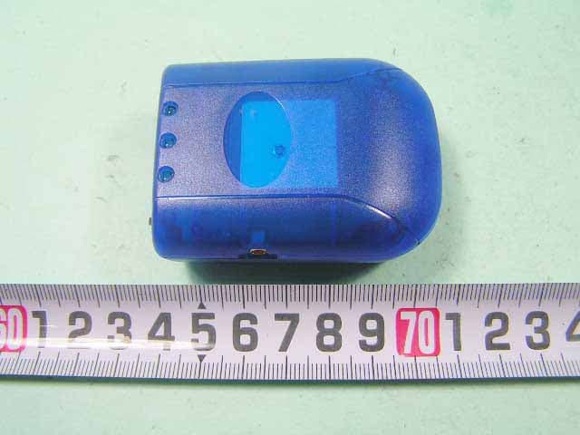
QW3-BTGPS02
Oct 27, 2005Bluetooth GPS Receiver
Equipment Class
DSS - Part 15 Spread Spectrum Transmitter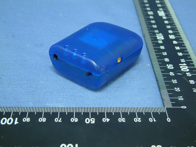
QW3-BTGPS01
Jul 12, 2005Bluetooth GPS Receiver
Equipment Class
DSS - Part 15 Spread Spectrum Transmitter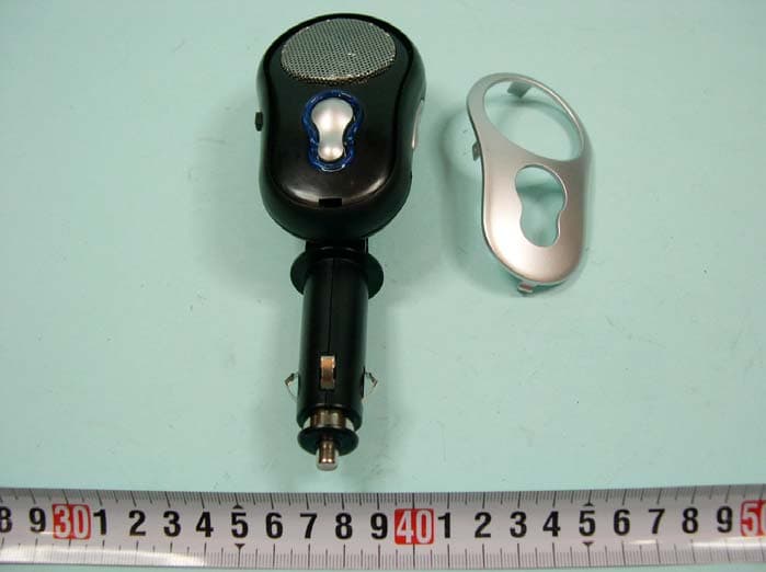
QW3-BTHCB01
Jun 02, 2005Bluetooth Car Kit
Equipment Class
DSS - Part 15 Spread Spectrum Transmitter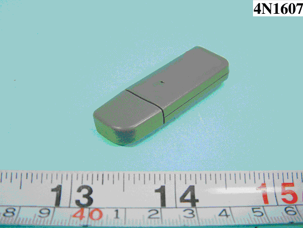
QW3-BTBA02B
Dec 09, 2004BLUETOOTH USB ADAPTER
Equipment Class
DSS - Part 15 Spread Spectrum Transmitter
QW3-BTBA02
Nov 30, 2004BLUETOOTH USB ADAPTER
Equipment Class
DSS - Part 15 Spread Spectrum Transmitter