QWP58XX-SWireless Ethernet Bridge
Cambium Networks Limited
Click to zoom
Application Details
- Equipment Class
- DSS - Part 15 Spread Spectrum Transmitter
- Date of Grant
- Mar 14, 2004
- Application Purpose
- Original Equipment
- Date of Application
- Mar 14, 2004
- Equipment Note
- Wireless Ethernet Bridge
- Frequency Range
- 5731.00000000 - 5844.00000000
- Company
- Cambium Networks Limited
- Country
- United Kingdom
Documents & Files
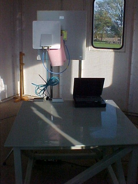
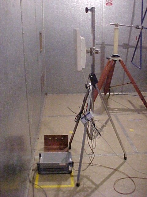
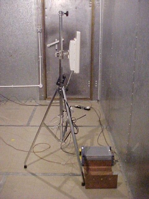
Document Text
Text extracted from the exhibit documents filed with the FCC. Open a document above to read the original.
Users Manual
PHN-0630-01.01 Orthogon Systems Gemini System User Manual February 24 th , 2004 Ref: PHN-0630-01.01 Copyright Information This document is the confidential property of PipingHot Networks Limited (trading as Orthogon Systems) and without its prior written consent may not be copied or released to 3rd parties. © 2004 PipingHot Networks Limited. Compliance Changes or modifications not expressly approved by Orthogon Systems could void the user’s authority to operate the system. NOTE: This system has been tested and found to comply with the limits for a Class B digital device 1 , pursuant to Part 15 of the FCC Rules. These limits are designed to provide reasonable protection against harmful interference in a residential installation. This equipment generates, uses and can radiate radio frequency energy and, if not installed and used in accordance with the instructions, may cause harmful interference to radio communications. However, there is no guarantee that interference will not occur in a particular installation. If this equipment does cause harmful interference to radio or television reception, which can be determined by turning the equipment off and on, the user is encouraged to try to correct the interference by one or more of the following measures: • Reorient or relocate the Outdoor Unit (ODU). • Increase the separation between the equipment and ODU. • Connect the equipment into a power outlet on a circuit different from that to which the receiver is connected. • Consult the dealer or an experienced radio/TV technician for help. 1 Class B Digital Device, A digital device that is marketed for use in a residential environment notwithstanding use in commercial, business and industrial environments. 1 Disclaimer The parameters quoted in this document must be specifically confirmed in writing before they become applicable to any particular order or contract. The company reserves the right to make alterations or amendments to the detail specification at its discretion. The publication of information in this document does not imply freedom from patent or other rights of Orthogon Systems or others. 2 Contents 1 Getting Started......................................6 1.1 For Your Safety....................................6 1.2 Welcome...............................................6 1.3 Product Description..............................8 1.4 Warranty.............................................13 2 Product Architecture..........................14 3 General Considerations.....................16 3.1 Frequency Planning...........................16 3.2 Distance..............................................16 3.3 Networking Information......................16 3.4 Lightning Protection............................16 3.5 Electrical Requirements.....................17 4 Site Planning.......................................18 4.1 Site Selection Criteria.........................18 5 Installation...........................................21 5.1 Preparation.........................................21 5.2 Installation Procedure.........................21 5.3 Tools Required...................................21 5.4 Installation Support.............................22 5.5 Legal Disclaimer.................................22 5.6 Mounting the ODUs............................22 5.7 Connecting Up....................................23 6 Web Page Reference..........................31 6.1 Home Page........................................31 6.2 Systems Status Page.........................33 6.3 System Administration Pages............38 7 Fault Finding.......................................68 7.1 Hardware............................................68 7.2 Radio..................................................71 8 Specifications.....................................72 8.1 System Specifications........................72 8.2 Safety Compliance.............................76 8.3 EMC Emissions Compliance..............76 8.4 EMC Immunity Compliance................77 8.5 Radio Certifications............................77 8.6 Environmental Specifications.............77 8.7 System Connections..........................78 9 Lightning Protection..........................79 9.1 Overview............................................79 9.2 Detailed Installation............................79 10 OS-Gemini C.......................................83 10.1 Scope.........................................83 10.2 Product Description....................83 10.3 Software/Features......................84 10.4 Deployment Considerations.......88 10.5 Link Budget................................88 10.6 Regulatory Issues......................89 10.7 Antennas for USA / Canada.......90 11 FAQs....................................................91 12 Glossary..............................................94 13 Index....................................................95 3 4 List of Figures Figure 1 Typical OS-Gemini Deployment.........................................................................................8 Figure 2 OS-Gemini Outdoor Unit (ODU).........................................................................................9 Figure 3 OS-Gemini Indoor Unit (IDU)...........................................................................................10 Figure 4 OS-Gemini Reset Switch Depressed...............................................................................10 Figure 5 OS-Gemini Power Adaptor...............................................................................................11 Figure 6 OS-Gemini Layer Diagram...............................................................................................14 Figure 7 Completed ODU connector..............................................................................................24 Figure 8 RJ45 Pin Connection........................................................................................................24 Figure 9 Disconnecting the ODU......................................…
Text truncated - open the document above for the full version.
Users Manual
51 6.3.4 Software Upgrade The OS-Gemini system has two software image banks; one is a fixed image which is stored in protected non-volatile memory, the second bank is used by the system administrator to upgrade the firmware as and when necessary. Figure 21 shows the main software upgrade webpage. Figure 21 Software Upgrade The ‘Fixed’ image is only used if disaster recovery is required, i.e. if an upgrade process is interrupted or the units are reset to their factory defaults. These pages are used to update a unit’s operational software. The software image to be uploaded should be downloaded to local storage from the Orthogon Systems website. The software image is delivered by Orthogon Systems as a compressed zip file. Once the zip file has been downloaded the user should extract the OS-Gemini Software image. This is easily identifiable by its ‘.dld’ file extension. The first step (Figure 21) is to use the “Browse” button to locate the software image previously downloaded to local storage from the Orthogon Systems website. Once the image is located the user should press the “Upload image to wireless unit” button to start the software upgrade process. 52 The software image will now be uploaded to the unit where it will be stored in SDRAM until it is committed to the unit’s non-volatile memory. This upload should only take a few seconds, once complete the image is verified and validated to ensure that no errors occurred during transfer and the image is valid to run on the current platform. If there are any problems a warning screen will appear. The unit being upgraded will now display information about the build it currently has stored in the image bank and the one that’s just been uploaded. If the image is not the right one the user has the option to go back and reload a new image. (See Figure 21) Figure 22 Software Upgrade Image Check The user should ensure that he is happy to proceed before pressing the “Program Software Image into Non-Volatile Memory” button. Once this button has been pressed the image is stored into non-volatile memory, this process can take up to 60 seconds and must not be interrupted. 53 Figure 23 Software Upgrade Complete When the software image has been written to non-volatile memory Figure 23 will be displayed showing the status of the software upload. Reset the unit by clicking the Reset Unit button. This will reset the unit within 30 seconds, during this time you will not be able to communicate with the unit. The unit is now fully functional. If this screen is not displayed after 60 seconds this could indicate a problem with the memory update process. The user should now power cycle the unit to start using the new software image. The unit’s boot software will automatically determine the health of the newly uploaded software image. If any problems were encountered the boot code will revert to a protected fixed software image After the power cycle the user should check that the required software image is loaded and running by re-entering the Upgrade page where the software bank status will be displayed. 54 6.3.5 Dynamic Frequency Selection (DFS) Dynamic Frequency Selection (hereafter referred to by the acronym DFS) is the OS-Gemini wireless feature that monitors the available wireless spectrum and directs both ends of the wireless link to operate on a channel with the minimum level of co and adjacent levels interference. 6.3.5.1 Wireless Channels The OS-Gemini wireless operates using a set of predefined overlapping channels. There are 19 predefined channels starting at 5734 MHz and ending at 5842 MHz. Each channel occupies 11 MHz of wireless spectrum and is offset in centre frequency from its neighbouring channel by 6 MHz. It is important to note that adjacent channels on the DFS display have a 5 MHz overlap to the adjacent channel. 6.3.5.2 DFS Measurements The OS-Gemini wireless units perform four DFS measurements per TDD cycle, per channel. The measurements are subdivided into two signal peak measurements and two mean signal measurements. The peak measurements represent the peak received signal power with a resolution down to 100 nS. The mean measurement represents the mean received signal power for the 40 μS measurement period. The DFS algorithm collects DFS measurements equally from all channels. This process is called the Channel Availability Check (hereafter referred to by the acronym CAC). The CAC uses a round-robin channel select process to collect an equal amount of DFS measurements from each channel. It is important to note that the CAC measurement process is not altered by channel barring process. Measurements are still collected for all channels irrespective of the number of barred channels. 6.3.5.3 Measurement Analysis DFS uses statistical analysis to process the received peak and mean measurement. The statistical analysis is based on a fixed measurement quantisation period. The default quantisation period is one minute. DFS collects data for the specified quantisation period and only at the end of the period is the statistical analysis performed. The analysis produces four key metrics for each channel: • Peak of Peaks • Peak of Means • 99.9% Percentile of the Means • Mean of Means 55 Peak of Peaks is the largest peak interference measurement encountered during the quantisation period. This metric is useful for detecting large short duration spikes in the interference environment. Peak of Means is the largest mean interference measurement encountered during the quantisation period. The peak of means is similar to the peak of peaks and is useful for detecting slightly longer duration spikes in the interference environment. 99.9% Percentile of the Means is the value of mean interference measurement for which 99.9% of all mean measurements fall below during the quantisation period. The 99.9% percentile metric is useful for detecting short duration repetitive interference that by its very nature has a minimal effect of the mean of means. Mean of Means is…
Text truncated - open the document above for the full version.
Cover Letter(s)
Unit A1, Linhay Business Park Eastern Road Ashburton Devon TQ13 7UP United Kingdom Tel: +44 (0)1364 655500 Fax: +44 (0)1364 654625 www.orthogonsystems.com 04 March 2004 Telecommunication Certification Body Radio Frequency Investigation Ltd. Ewhurst Park Ramsdell Basingstoke Hampshire RG26 5RQ England Subject: Certification Application for FCC ID: QWP58XX-S Dear Sirs It is requested that the following information is to be held confidential on behalf of Orthogon Systems. The only new item in this submission is the Operational Description of OS58XX-S; the remaining information is unchanged from the previous submissions for FCC ID: QWP58XX and QWP58XX-T. Item No of Files Pages Per File ODU RF Block Diagram 1 1 in .pdf OS58XX-S Operational Description 1 5 in .pdf ODU Digital Block Diagram 1 1 in .pdf ODU Digital Schematics 1 17 in .pdf ODU RF Schematics 1 22 in .pdf IDU Schematics 1 1 in .pdf Bills of Material 4 ODU RF ODU Digital IDU Overall ODU RF - 8 pages in .pdf ODU Dig - 4 pages in .pdf IDU - 2 pages in .pdf Overall - 1 page in .pdf Reasons for Confidentiality Request 1. Orthogon Systems is proposing to market the OS58XX-S product (also known as Gemini) as a Wireless Ethernet Bridge operating at 5.8GHz. This is a highly competitive market where Orthogon believes its product will have significant performance advantage in terms of its operation in Non Line-of-Sight conditions. The materials listed above identify the methods used in the product to achieve the performance advantage and contain significant Intellectual Property developed by Orthogon Systems. The publication of some or all of the information could allow this performance advantage to be unfairly eroded by the competitors of Orthogon Systems. 2. Orthogon Systems has entered into non-disclosure agreements during the development process with some of its key component suppliers. Publication of schematics and Bills of Material would compromise those agreements. 3. Orthogon Systems has taken steps during development of the product to keep confidential its plans: a. The Orthogon Systems web site was only upgraded to give brief details of the product once the formal launch date was finalised. b. Technical papers produced by Orthogon Systems do not identify how the performance advantage is achieved c. Prior disclosure to 3 rd parties has always been under the terms of specific non-disclosure agreement. 4. Orthogon Systems believes that no benefit would accrue to the general public in the event of publication of the material listed. The only beneficiaries would be the competitors of Orthogon Systems. 5. Orthogon Systems believes that the material listed should be kept confidential for a period of 5 years from the date of submission in order to prevent its competitors from copying its technology. Yours Sincerely Clem Fisher RF Development Manager
ID Label/Location Info
OS-Gemini Outdoor Unit Product Code: PHN1678 Made in: United Kingdom Power Requirements: 48V 0.9A CAUTION: This product must be installed in accordance with the instructions in the User Manual Complies with UL60950 CSA C22.2 No. 60950 LISTING No: E112443 FCC ID: QWP58XX-S This device complies with Part 15 of the FCC Rules.Operation is subject to the following two conditions:1 This device may not cause harmful interference, and 2 This device must accept any interference received, including interference that may cause undesired operation. IC:4815A-58XXSSerial NumberMAC Address OS Label artwork (back x2) 9/3/04 12:46 pm Page 3 (Black plate) OS-Gemini Outdoor Unit Product Code: 1806 Made in: United Kingdom Power Requirements: 48V 0.9A CAUTION: This product must be installed in accordance with the instructions in the User Manual Complies with UL60950 CSA C22.2 No. 60950 LISTING No: E112443 FCC ID: QWP58XX-S This device complies with Part 15 of the FCC Rules.Operation is subject to the following two conditions:1 This device may not cause harmful interference, and 2 This device must accept any interference received, including interference that may cause undesired operation. IC:4815A-58XXSSerial NumberMAC Address OS Label artwork (back x2) 9/3/04 12:46 pm Page 4 (Black plate)
RF Exposure Info
Integrated IDU Requirement Spec phn-0619 v 0.002 CF Page 1 of 5 Orthogon Systems Working Paper Analysis of the FCC Regulations for Radiation Safe Distance with respect to the Gemini 58XX-S Range of Products C.F.Fisher Ref: phn-0619 Abstract This document analyses the exclusion zone required to ensure human radiation level limits are not exceeded by the Gemini 58XX-S range of products with integrated or external antennas. The guidelines in FCC Bulletin 65 are used to compute the safe distances. This document is the confidential property of Orthogon Systems Ltd and without its prior consent may not be copied or released to 3 rd parties. The parameters quoted in this document must be specifically confirmed in writing before they become applicable to any particular order or contract. The company reserves the right to make alterations or amendments to the detail specification at its discretion. The publication of information in this document does not imply freedom from patent or other rights of Orthogon Systems or others. Integrated IDU Requirement Spec phn-0619 v 0.002 CF Page 2 of 5 Orthogon Systems Revision History Version Date Comments Author 0.001 24 November 2003 Initial Issue CF 0.002 5 February 2004 Update for 58XX-S CF Integrated IDU Requirement Spec phn-0619 v 0.002 CF Page 3 of 5 Orthogon Systems Operational Parameters of the Gemini 58XX-S Products 1 Scope The purpose of this brief working paper is to identify the mean RF power produced by the Gemini 58XX-S equipments under various operating conditions. This mean RF power plus the antenna gain used in specific installations identifies the effective power density (dBm/cm 2 ) that is to be compared against allowed limits for human exposure. 2 References Evaluating Compliance with FCC Guidelines for Human Exposure to Radio frequency Electromagnetic Fields: OET Bulletin 65, Edition 97-01, August 1997 [1] 3 Background Reference [1] identifies how the radiated power density should be calculated for different distances from the antenna. The variables used are Radiated Power Density (S), conducted power (P), Antenna Gain (G) and distance (R) . The formula given is S= (P * G)/(4 * Pi * R) 2 The limit allowed for S depends on whether the exposure risk is to a member of the public or not. The limits for public exposure are the lower, and so a power density limit of 1mW/cm 2 is used for S. This is used to compute a ‘safe’ distance from the antenna. It is clear from [1] that the power to be used should be the RMS power averaged over a period of 6 minutes. 4 Gemini 58XX-S Specific Issues 4.1 FCC Testing The Gemini 58XX is approved under section 15.247 and the only RF power level measured is the Peak Envelope Power during the transmission bursts. The measurement is either done using a spectrum analyser (set to use peak detector, maximum resolution bandwidth, maximum video bandwidth and with the analyser set to max hold) or with a peak reading power meter. If this power level is used for the computation of ‘safe distance’ the result is unduly pessimistic. 4.2 Errors in Using the FCC Recorded Power Levels The errors arise from : a) the Gemini 58XX-S operates as a Time Division Duplex System and transmits for up to 58% of the time, over a period of approximately 4msec. The actual transmit/receive burst duration is shown in the plot below. Integrated IDU Requirement Spec phn-0619 v 0.002 CF Page 4 of 5 Orthogon Systems This shows a transmit duty cycle of (4.175-2.637)/(4.175-1.538) or 0.583. This corresponds to a difference of 2.34dB between the power during the burst and the mean power level.. b) the formal measurements record peak envelope power, and the OFDM waveform used has a high peak to mean difference. The actual difference depends on modulation mode, but for the case the mode used at maximum power, the peak to mean approaches 6dB. Gemini 58XX uses an RF detector and a control loop to hold the power level at the closely to the set level. Gemini has a maximum setting for the mean power output of 24dBm (both channels together). The mean transmitted power level is reduced to this level to ensure meeting the peak envelope power limits contained in 15.247. c) In the case of the external antennas, the tests were performed with a cable loss of 1.2dB; the handbook mandates that this is the minimum cable loss that can be used. 5 Recommendations It is recommended that the power level used for computing the ‘safe distance’ for human exposure is either Integrated IDU Requirement Spec phn-0619 v 0.002 CF Page 5 of 5 Orthogon Systems a) the nominal maximum power output less the allowance for the duty cycle. This is 24dBm –2.34dB or 21.66dBm. The safe distance calculations for the different antennas are shown below on this basis. b) The power level in (a) less the minimum cable losses. Safe distance calculations are also included for this case. Total Mean Transmit PowerdBm mW mW incl cable loss Safety Power Density LimitmW/cm2 Antenna Type Manufacturer's Gain (dBi) Safe Distance for 0dB Cable Loss (m) Safe Distance for 1.2dB Cable Loss (m) Integrated23.50.51N/A 2 ft Flat Plate280.860.75 2ft Parabolic Dish28.50.910.79 3ft Parabolic Dish31.51.281.12 4ft Parabolic Dish34.51.811.58 6ft Parabolic Dish37.72.622.28 21.66 146.55 1 111.17
Test Report
Radio Frequency Investigation Ltd, Ewhurst Park, Ramsdell, Basingstoke, Hampshire, RG26 5RQ, ENGLAND. Tel: +44 (0) 1256 851193 Fax: +44 (0) 1256 851192 Registered in England, No. 211 7901. Registered Office: Ewhurst Park, Ramsdell, Basingstoke, Hampshire RG26 5RQ TESTING 0644 TEST REPORT FROM RADIO FREQUENCY INVESTIGATION LTD. Test Of: Orthogon Systems Gemini OS58XX To: FCC Part 15.247 Test Report Serial No: RFI/MPTB3/RP45840JD01A Supersedes Test Report Serial No: RFI/MPTB2/RP45840JD01A This Test Report Is Issued Under The Authority Of Richard Jacklin, Operations Director: Checked By: Tested By: pp Release Version No: PDF01 Issue Date: 15 March 2004 Test Dates: 03 February 2004 to 04 February 2004 This report is issued in Adobe Acrobat portable document format (PDF). It is only a valid copy of the report if it is being viewed in PDF format with the following security options not allowed: Changing the document, Selecting text and graphics, Adding or changing notes and form fields. Furthermore, the date of creation must match the issue date stated above. This report may be copied in full. The results in this report apply only to the sample(s) tested. RADIO FREQUENCY INVESTIGATION LTD TEST REPORT S.No. RFI/MPTB3/RP45840JD01A Operations Department Page 2 of 74 Issue Date: 15 March 2004 Test Of: Orthogon Systems Gemini OS58XX To: FCC Part 15.247 This page has been left intentionally blank. RADIO FREQUENCY INVESTIGATION LTD TEST REPORT S.No. RFI/MPTB3/RP45840JD01A Operations Department Page 3 of 74 Issue Date: 15 March 2004 Test Of: Orthogon Systems Gemini OS58XX To: FCC Part 15.247 Table of Contents 1. Client Information..........................................................................................................4 2. Equipment Under Test (EUT) .......................................................................................5 3. Methods And Procedures...........................................................................................10 4. Deviations From The Test Specification ...................................................................11 5. Operation Of The EUT During Testing ......................................................................12 6. Summary Of Test Results...........................................................................................14 7. Measurements, Examinations And Derived Results................................................15 8. Test Results – Full Power...........................................................................................16 9. Test Results – Reduced Power ..................................................................................51 10. Measurement Methods .............................................................................................66 11. Measurement Uncertainty ........................................................................................72 Appendix 1. Test Equipment Used ................................................................................73 Test Report Serial No: RFI/MPTB3/RP45840JD01A Supersedes Test Report Serial No: RFI/MPTB2/RP45840JD01A RADIO FREQUENCY INVESTIGATION LTD TEST REPORT S.No. RFI/MPTB3/RP45840JD01A Operations Department Page 4 of 74 Issue Date: 15 March 2004 Test Of: Orthogon Systems Gemini OS58XX To: FCC Part 15.247 1. Client Information Company Name: Orthogon Systems Address: Unit 1A, Linhay Business Park Eastern Road Ashburton Devon TQ13 7UP Contact Name: Clem Fisher RADIO FREQUENCY INVESTIGATION LTD TEST REPORT S.No. RFI/MPTB3/RP45840JD01A Operations Department Page 5 of 74 Issue Date: 15 March 2004 Test Of: Orthogon Systems Gemini OS58XX To: FCC Part 15.247 2. Equipment Under Test (EUT) The following information (with the exception of the Date of Receipt) has been supplied by the client: 2.1. Identification Of Equipment Under Test (EUT) Description: Outdoor Unit Brand Name: Gemini Model Name or Number: OS58XX Serial Number 00:03:01 Country of Manufacture: UK System FCC ID: QWP58XX-S Date of Receipt: 03 February 2004 Description: Indoor Unit Brand Name: Gemini Model Name or Number: OS58XX Serial Number: 14 Country of Manufacture: UK Date of Receipt: 03 February 2004 Description: System Power Supply Brand Name: Hitron Electronics Corporation Model Name or Number: HES51-48010 Serial Number: 0053 Country of Manufacture: Taiwan Date of Receipt: 03 February 2004 RADIO FREQUENCY INVESTIGATION LTD TEST REPORT S.No. RFI/MPTB3/RP45840JD01A Operations Department Page 6 of 74 Issue Date: 15 March 2004 Test Of: Orthogon Systems Gemini OS58XX To: FCC Part 15.247 2.2. Description Of EUT The Gemini 58XX is a point to point Ethernet Bridge radio equipment operating in the band 5725 MHz to 5850 MHz (USA band limits). There are 3 parts to the equipment. Outdoor Unit, which comprises of an electronics enclosure and an integral, dual polarised antenna. The ODU contains all the main electronic components in the system and generates all the RF frequencies. It has two antenna ports one for the vertical antenna and one for the horizontal antenna. The equipment may be operated in BPSK, QPSK, 16QAM, 64QAM or Acquisition modulation modes, which are selected via software control. All modes of modulation use the same hardware. Indoor Unit, which provides an interface box between the ODU, the power supply and the customer’s LAN network. This unit comprises basically of connectors, some LEDs and filters. A mains power supply adapter from an external supplier provides all the DC supply for the rest of the system. The system is connected by CAT5 cables, which may be screened or unscreened. The Gemini OS58XX is available in two versions. The first is fitted with an integral antenna and the second is a connectorised version for use with external antennas and is fitted with a cover plate containing two N type connectors. The fundamental product is otherwise identical in both versions – the version to be shipped is decided on the basis of current production orders. 2.3. Mo…
Text truncated - open the document above for the full version.
Contact Information
Applicant
Dominic Holton(Mr)
Technical Contact
Orthogon Systems LtdClem Fisher
[email protected]+44 1364 655500
Unit A Linhay Business Park · Ashburton · United Kingdom
Test Firm
RFI Global Services Ltd.Allan Hume
Technical Specifications
| # | Rule Parts | Frequency Range | Power Output |
|---|---|---|---|
| 1 | 15C | 5.73 GHz - 5.84 GHz | 759.00 mW |
Other Applications from Cambium Networks Limited

QWP-60V3000
Nov 10, 202060 GHz Outdoor Wireless Gigabit Ethernet Bridge
Equipment Class
DXX - Part 15 Low Power Communication Device Transmitter
QWP-60V1000
Nov 10, 202060 GHz Outdoor Wireless Gigabit Ethernet Bridge
Equipment Class
DXX - Part 15 Low Power Communication Device Transmitter
QWP-60V5000
Nov 10, 202060 GHz Outdoor Wireless Gigabit Ethernet Bridge
Equipment Class
DXX - Part 15 Low Power Communication Device Transmitter
QWP-50450I
May 21, 2015Wireless Ethernet Bridge, Dual Channel OFDM MIMO Combination Access Point, Subscriber Station and Point to Point Equipment
Equipment Class
DTS - Digital Transmission System
QWP5X250
Feb 01, 2012Wireless Ethernet Bridge
Equipment Class
DTS - Digital Transmission System