QXZGWTSPP1Bluetooth Serial Port Dongle
Gigawavetech Pte Ltd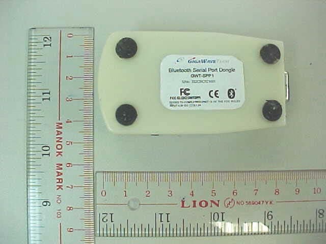
Click to zoom
Application Details
- Equipment Class
- DSS - Part 15 Spread Spectrum Transmitter
- Date of Grant
- Sep 18, 2003
- Application Purpose
- Original Equipment
- Date of Application
- Sep 18, 2003
- Equipment Note
- Bluetooth Serial Port Dongle
- Frequency Range
- 2402.00000000 - 2480.00000000
- Company
- Gigawavetech Pte Ltd
- Country
- Singapore
Documents & Files
Document Text
Text extracted from the exhibit documents filed with the FCC. Open a document above to read the original.
Users Manual
Bluetooth™ Serial Port Dongle GWT-SPP1 Users’ Guide The easy way to add Bluetooth functionality to your equipment with a serial port. GigaWaveTech (Pte) Ltd (a member of schmidt electronics asia) DISCLAIMER: This manual is published by GigaWaveTech Pte Ltd, without any warranty. Improvements and changes to this manual necessitated by typographical errors, inaccuracies of current information or improvements to equipment may be made by GigaWaveTech Pte Ltd at any time and without notice. Such changes will however be incorporated into new editions of this manual. Hardware, software and firmware mentioned in this document are subject to continuous development and improvement. Consequently, there may be discrepancies between the information in this document and the performance and design of the product. Table of Contents Introduction................................................................................................................ 4 Accessories............................................................................................................... 4 Parts of the GWT-SPP1............................................................................................. 4 Installation Procedure................................................................................................ 5 Connecting to a Host PC........................................................................................ 5 Connecting to Power Source.................................................................................. 5 Transferring Data from Other Bluetooth Devices to Host PC..................................... 6 Using the Light Emitting Diodes (LEDs)..................................................................... 7 Using the Pairing Switch............................................................................................ 7 Troubleshooting......................................................................................................... 8 Specifications............................................................................................................. 9 Useage & Safety Considerations............................................................................. 11 Appendix A: Limited Product Warranty............................................................... 13 Copyright Notice...................................................................................................... 15 Regulatory Compliance Notice................................................................................ 16 Life Support Policy................................................................................................... 17 INTRODUCTION Congratulations on the purchase of your GigaWaveTech Bluetooth Serial Port Dongle GWT- SPP1. The GWT-SPP1 is a plug and play adapter that allows you to easily add Bluetooth wireless connectivity to the serial port of your equipment. In itself, the GWT-SPP1 does not require installation of software or drivers on the host machine. The dongle does not initiate communications, but simply acts as a substitute for a wired serial connection. The adapter employs Bluetooth technology compliant to the BT 1.1 specifications and consists of a transceiver operating in the 2.4 GHz range. The operating range of the GWT- SPP1 has been tested to reach up to 50m in line-of-sight communication and up to 10m in typical indoor environment. It provides link control functionality and supports operation within a Bluetooth net in the slave mode. In the current release, it supports fixed interface baud rate of 115.2kbps using 8-bit data with 1 start, 1 stop-bit and no parity. This Users’ Guide shows you how to quickly install the dongle for communication with other Bluetooth devices support serial port profile. ACCESSORIES Each GWT-SPP1 requires a 4.5V dc AC-DC adaptor as power source. In addition, a 9-pin straight cable with a male connector at one end and a female connector at the other end is supplied. This cable may be used when there is not enough space to directly connect the GWT-SPP1 dongle to the serial port connector of a host PC or when poor wireless reception is encountered and locating the dongle away from the PC is desirable. PARTS OF THE GWT-SPP1 Pairing Switch Green LED Red LED Power Port 9-pin Serial Port Connector INSTALLATION PROCEDURE Connecting to a Host PC To use the dongle to provide serial communication between other Bluetooth device and a host PC: 1. The dongle serial port connector can be connected directly to the serial port of a host PC. However, in situation where connection is difficult or better wireless reception is desired by keeping the dongle away from the host PC, the serial cable can be used. 2. Connect the male end of a serial cable to the dongle serial port. 3. Connect the other end of the serial cable to the host PC. (Note: The dongle requires a dedicated serial port on the host PC. It cannot share a port with an internal modem or other device) 4. Power up the dongle following the procedure outlined in Connecting to Power Source. 5. The Host PC is ready to receive data from other Bluetooth devices through the serial port with the serial port settings matching that of the GWT-SPP1. The GWT-SPP1 has an interface configuration of baud rate 115.2kbps, using 8-bit data with 1 start and 1 stop bit. Connecting to Power Source The AC-DC adaptor provides power to the GWT-SPP1 dongle. Use only a GWT-approved power adaptor with output rated 4.5V DC and minimum current of 0.2 Ampere. To connect the power source to the dongle: 1. Connect the DC out put of the AC-DC adaptor to the power port of the dongle located at the side of it. 2. Connect the other end of the AC-DC adaptor to a wall outlet. 3. Switch on the wall outlet and checks that the green LED is lighted (see Using the LEDs for more information). TRANSFERRING DATA FROM OTHER BLUETOOTH DEVICES TO HOST PC The GWT-SPP1 dongle is shipped with a set of pre-configured parameters. The pre…
Text truncated - open the document above for the full version.
Block Diagram
TÜV Rheinland Product Safety GmbH Am Grauen Stein D - 51105 Köln Appendix 4 Prüfbericht - Nr.: Test Report No. 14004426 001 Seite 3 von 12 Page 3 of 12 2.2 Block Diagram 2.2.1 Block Diagram of GWT-SPP1 TÜV Rheinland Product Safety GmbH Am Grauen Stein D - 51105 Köln Appendix 4 Prüfbericht - Nr.: Test Report No. 14004426 001 Seite 4 von 12 Page 4 of 12
External Photos
TÜV Rheinland Product Safety GmbH Am Grauen Stein D - 51105 Köln Appendix 3 Prüfbericht - Nr.: Test Report No. 14004426 001 Seite 1 von 8 Page 1 of 8 Gigawavetech Bluetooth Serial Port Dongle Front side of external view: TÜV Rheinland Product Safety GmbH Am Grauen Stein D - 51105 Köln Appendix 3 Prüfbericht - Nr.: Test Report No. 14004426 001 Seite 2 von 8 Page 2 of 8 Rear side of external view: TÜV Rheinland Product Safety GmbH Am Grauen Stein D - 51105 Köln Appendix 3 Prüfbericht - Nr.: Test Report No. 14004426 001 Seite 3 von 8 Page 3 of 8 Side view of external view: TÜV Rheinland Product Safety GmbH Am Grauen Stein D - 51105 Köln Appendix 3 Prüfbericht - Nr.: Test Report No. 14004426 001 Seite 4 von 8 Page 4 of 8 TÜV Rheinland Product Safety GmbH Am Grauen Stein D - 51105 Köln Appendix 3 Prüfbericht - Nr.: Test Report No. 14004426 001 Seite 5 von 8 Page 5 of 8
ID Label/Location Info
TÜV Rheinland Product Safety GmbH Am Grauen Stein D - 51105 Köln Appendix 4 Prüfbericht - Nr.: Test Report No. 14004426 001 Seite 1 von 12 Page 1 of 12 1.1 FCCID Label Artwork
Internal Photos
TÜV Rheinland Product Safety GmbH Am Grauen Stein D - 51105 Köln Appendix 3 Prüfbericht - Nr.: Test Report No. 14004426 001 Seite 6 von 8 Page 6 of 8 Front side of internal view: The yellow oval indicates the location of the antenna. TÜV Rheinland Product Safety GmbH Am Grauen Stein D - 51105 Köln Appendix 3 Prüfbericht - Nr.: Test Report No. 14004426 001 Seite 7 von 8 Page 7 of 8 Rear side of internal view: TÜV Rheinland Product Safety GmbH Am Grauen Stein D - 51105 Köln Appendix 3 Prüfbericht - Nr.: Test Report No. 14004426 001 Seite 8 von 8 Page 8 of 8 Side view of internal view 1:
Operational Description
TÜV Rheinland Product Safety GmbH Am Grauen Stein D - 51105 Köln Appendix 4 Prüfbericht - Nr.: Test Report No. 14004426 001 Seite 2 von 12 Page 2 of 12 2.1 Description of Circuit Function 2.1.1 General Description Bluetooth operates in the unlicensed ISM band at 2.4 GHz. A frequency hop transceiver is applied to combat interference and fading. A shaped, binary FM modulation is applied to minimize transceiver complexity. The symbol rate is 1 Ms/s. A slotted channel is applied with a nominal slot length of 625 μs. For full duplex transmission, a Time-Division Duplex (TDD) scheme is used. On the channel, information is exchanged through packets. Each packet is transmitted on a different hop frequency. A packet nominally covers a single slot, but can be extended to cover up to five slots. The Bluetooth protocol uses a combination of circuit and packet switching. Slots can be reserved for synchronous packets. Bluetooth can support an asynchronous data channel, up to three simultaneous synchronous voice channels, or a channel which simultaneously supports asynchronous data and synchronous voice. Each voice channel supports a 64 kb/s synchronous (voice) channel in each direction. The asynchronous channel can support maximal 723.2 kb/s asymmetric (and still up to 57.6 kb/s in the return direction), or 433.9 kb/s symmetric. The Bluetooth system consists of a radio unit, a link control unit, and a support unit for link management and host terminal interface functions.
Test Report
TÜV Rheinland Product Safety GmbH Am Grauen Stein D - 51105 Köln Prüfbericht - Nr.: Test Report No. 14004426 001 Seite 2 von 19 Page 2 of 19 1 Test Summary 7.1.1 ANTENNA CONNECTOR SUBCLAUSE 15.203 7.1.2 A NTENNA TYPE SUBCLAUSE 15.204 7.1.3 DISTURBANCE VOLTAGE ON AC MAINS SUBCLAUSE 15.207(A) RESULT: Pass Limit Subclause 15.207(a) 7.1.4 C ARRIER FREQUENCY SEPERATION SUBCLAUSE 15.247(A)(1) RESULT: Pass Limit Subclause 15.247(a)(1) 7.1.5 DWELL TIME SUBCLAUSE 15.247(A)(1)(III) RESULT: Pass Limit Subclause 15.247(a)(1)(iii) 7.1.6 20DB BANDWIDTH SUBCLAUSE 15.247(A)(1) RESULT: Pass Limit Subclause 15.247(a)(1)(ii) 7.1.7 HOPPING SEQUENCE SUBCLAUSE 15.247(A)(1) 7.1.8 RECEIVER INPUT BANDWIDTH SUBCLAUSE 15.247(A)(1) 7.1.9 P EAK OUTPUT POWER SUBCLAUSE 15.247(B)(1) RESULT: Pass Limit Subclause 15.247(b)(1) 7.1.10 B AND EDGE COMPLIANCE SUBCLAUSE 15.247(C) RESULT: Pass Limit Subclause 15.247(c) 7.1.11 S PURIOUS CONDUCTED EMISSIONS SUBCLAUSE 15.247(C) RESULT: Pass Limit Subclause 15.247(c) 7.1.12 S PURIOUS RADIATED EMISSIONS SUBCLAUSE 15.247(C) RESULT: Pass Limit Subclause 15.247(c) TÜV Rheinland Product Safety GmbH Am Grauen Stein D - 51105 Köln Prüfbericht - Nr.: Test Report No. 14004426 001 Seite 3 von 19 Page 3 of 19 2 Contents 1 TEST SUMMARY..................................................................................................................2 2 C ONTENTS...........................................................................................................................3 3 GENERAL REMARKS...........................................................................................................4 3.1 COMPLEMENTARY MATERIALS..........................................................................................4 4 TEST SITES..........................................................................................................................4 4.1 TEST FACILITIES.................................................................................................................4 4.2 L IST OF TEST AND MEASUREMENT INSTRUMENTS............................................................5 5 GENERAL PRODUCT INFORMATION...................................................................................6 5.1 PRODUCT FUNCTION AND INTENDED USE..........................................................................6 5.2 R ATINGS AND SYSTEM DETAILS.........................................................................................6 5.3 INDEPENDENT OPERATION MODES....................................................................................6 5.4 SUBMITTED DOCUMENTS....................................................................................................7 6 T EST SET-UP AND OPERATION MODE................................................................................7 6.1 P RINCIPLE OF CONFIGURATION SELECTION.....................................................................7 6.2 T EST OPERATION AND TEST SOFTWARE............................................................................7 6.3 S PECIAL ACCESSORIES AND AUXILIARY EQUIPMENT.......................................................7 7 T EST RESULTS.....................................................................................................................8 7.1.1 Antenna connector Subclause 15.203 ........................................................................................................ 8 7.1.2 Antenna type Subclause 15.204.................................................................................................................. 8 7.1.3 Disturbance voltage on AC mains Subclause 15.207(a) ............................................................................9 7.1.4 Carrier frequency seperation Subclause 15.247(a)(1).............................................................................10 7.1.5 Dwell time Subclause 15.247(a)(1)(iii) .................................................................................................... 11 7.1.6 20dB bandwidth Subclause 15.247(a)(1) ................................................................................................. 12 7.1.7 Hopping sequence Subclause 15.247(a)(1).............................................................................................. 13 7.1.8 Receiver input bandwidth Subclause 15.247(a)(1) .................................................................................. 14 7.1.9 Peak output power Subclause 15.247(b)(1) ............................................................................................. 15 7.1.10 Band edge compliance Subclause 15.247(c) .......................................................................................16 7.1.11 Spurious conducted emissions Subclause 15.247(c) ........................................................................... 17 7.1.12 Spurious radiated emissions Subclause 15.247(c) .............................................................................. 18 TÜV Rheinland Product Safety GmbH Am Grauen Stein D - 51105 Köln Prüfbericht - Nr.: Test Report No. 14004426 001 Seite 4 von 19 Page 4 of 19 3 General Remarks 3.1 Complementary Materials All attachments are integral parts of this test report. This applies especially to the following appendix: Appendix 1: Test Results Appendix 2: Test Setup Appendix 3: EUT Photos Appendix 4: FCCID Label, Block Diagram and Schematics 4 Test Sites 4.1 Test Facilities Hong Kong Productivity Council HKPC Building 78 Tat Chee Avenue Kowloon Hong Kong TÜV Rheinland Product Safety GmbH Am Grauen Stein D - 51105 Köln Prüfbericht - Nr.: Test Report No. 14004426 001 Seite 5 von 19 Page 5 of 19 4.2 List of Test and Measurement Instruments Table 1: List of Test and Measurement Equipment Kind of Equipment Manufacturer Type S/N Test Receiver Rohde & Schwarz ESH-3 890173/033 L/I/S/N Rohde & Schwarz ESH 3-Z5 849876/026 Oscilloscope HP 54713B US34510455 Test Receiver Rohde & Schwarz ESVP 882402/033 Absorbing Clamp Rohde …
Text truncated - open the document above for the full version.
Test Setup Photos
TÜV Rheinland Product Safety GmbH Am Grauen Stein D - 51105 Köln Appendix 2 Prüfbericht - Nr.: Test Report No. 14004426 001 Seite 1 von 4 Page 1 of 4 1.1 Test set-up Spurious Radiated Emissions TÜV Rheinland Product Safety GmbH Am Grauen Stein D - 51105 Köln Appendix 2 Prüfbericht - Nr.: Test Report No. 14004426 001 Seite 2 von 4 Page 2 of 4 TÜV Rheinland Product Safety GmbH Am Grauen Stein D - 51105 Köln Appendix 2 Prüfbericht - Nr.: Test Report No. 14004426 001 Seite 3 von 4 Page 3 of 4 TÜV Rheinland Product Safety GmbH Am Grauen Stein D - 51105 Köln Appendix 2 Prüfbericht - Nr.: Test Report No. 14004426 001 Seite 4 von 4 Page 4 of 4 Disturbance voltage on AC mains
Contact Information
Applicant
Michael Soeding(Managing Director)
Technical Contact
T�V Rheinland Hong Kong Ltd.Stephan Wald
[email protected]+852 2192 1000
Room 405, Tech Centre · Hong Kong · Hong Kong
Non-Technical Contact
Gigawavetech Pte LtdMichael Soeding
[email protected]+65 63774801
Test Firm
Hong Kong Productivity CouncilIr Angel Wong Yuen-yee
Technical Specifications
| # | Rule Parts | Frequency Range | Power Output |
|---|---|---|---|
| 1 | 15C | 2.40 GHz - 2.48 GHz | 2.00 mW |
Other Applications from Gigawavetech Pte Ltd
QXZGWTBTH1
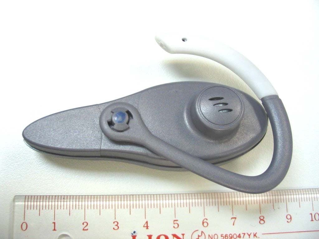
Dec 21, 2003Bluetooth Headset
Equipment Class
DSS - Part 15 Spread Spectrum Transmitter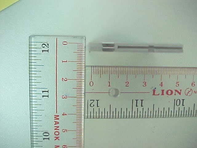
QXZCFSF-CL2
Sep 18, 2003Bluetooth Class 2 CF Adapter GWT-SFF
Equipment Class
DSS - Part 15 Spread Spectrum Transmitter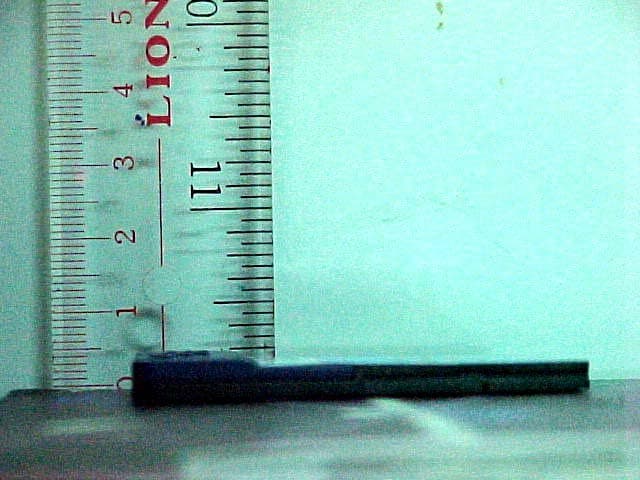
QXZCFPA-001A
Jul 27, 2003Bluetooth Compact Flash Card (Class 1)
Equipment Class
DSS - Part 15 Spread Spectrum Transmitter
QXZCFPA-001
Jul 07, 2003Bluetooth Compact Flash Card (Class 1)
Equipment Class
DSS - Part 15 Spread Spectrum Transmitter
QXZCFSC-CL2
Apr 22, 2003Bluetooth Compact Flash Card (Class 2)
Equipment Class
DSS - Part 15 Spread Spectrum Transmitter