QY9-AVBPBluetooth Pendant Headset
Addvalue Communications Pte Ltd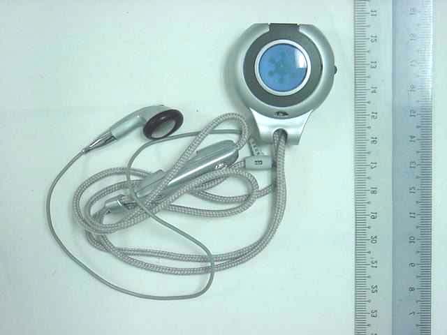
Click to zoom
Application Details
- Equipment Class
- DSS - Part 15 Spread Spectrum Transmitter
- Date of Grant
- Mar 29, 2003
- Application Purpose
- Original Equipment
- Date of Application
- Mar 29, 2003
- Equipment Note
- Bluetooth Pendant Headset
- Frequency Range
- 2402.00000000 - 2480.00000000
- Country
- Singapore
Documents & Files
Document Text
Text extracted from the exhibit documents filed with the FCC. Open a document above to read the original.
Users Manual
FCC INFORMATION FCC Compliance This device complies with Part 15 of the FCC Rules. Operation is subject to the following two conditions: (1) This device may not cause harmful interference, and (2) this device must accept any interference received, including interference that may cause undesired operation. NOTE: This equipment has been tested and found to comply with the limits for a Class B digital device, pursuant to Part 15 of the FCC Rules. These limits are designed to provide reasonable protection against harmful interference in a residential installation. This equipment generates, uses and can radiate radio frequency energy and, if not installed and used in accordance with the instructions, may cause harmful interference to radio communications. However, there is no guarantee that interference will not occur in a particular installation. If this equipment does cause harmful interference to radio or television reception, which can be determined by turning the equipment off and on, the user is encouraged to try to correct the interference by one or more of the following measures: -- Reorient or relocate the receiving antenna. -- Increase the separation between the equipment and receiver. -- Connect the equipment into an outlet on a circuit different from that to which the receiver is connected. -- Consult the dealer or an experience radio/TV technician for help for help. Any changes or modifications not expressly approved by the party responsible for compliance could void the user’s authority to operate the equipment. No special accessory is required to enable the equipment to comply with the emission limits. • Incoming Call • Outgoing Call • Call Waiting • Voice Control • Volume Control Contents Getting Started Using Your BluePendant Charging Troubleshooting Unpacking Contents • Power On/Off • Pairing Process • Pairing to a Mobile Phone • Deleting Pairing Information • Modes • Low Battery 2 3 7 12 14 1 Additional Information17 77A55017030 Your package should have: • BluePendant BP100 (Fig 1) • Power Adaptor (Fig 2) • Rechargeable Battery (Fig 3) CALL Button Indicator Light Power / Volume Button (PWR / VOL ) Power Jack Unpacking Contents 2 Unpacking Contents Fig 1 : Picture of Connecting Earpiece & Mic from the BluePendant Fig 2 : Power Adaptor Fig 3 : Rechargeable Battery Getting Started 3 Getting Started Before the BluePendant can be used for the first time, the BluePendant battery must be charged with the supplied power adapter according to steps found in page 12 for Charging. Power ON / OFF • To Power ON, press and hold PWR/VOL button until a BEEP is heard in the BluePendant earpiece. The indicator light turns Blue for 3 seconds. Thereafter, the indicator light will either flash Blue, once every 2 seconds (when paired) or alternating Blue and Orange (when not paired). • To Power OFF, press and hold the PWR/VOL button until the indicator light turns OFF. A series of beeps will be heard in the BluePendant earpiece and the PWR/VOL button is to be released. • The BluePendant cannot be turned OFF during Charging and when there is a call in process. Pairing Process Before the BluePendant can be used, it must be paired with a Bluetooth-enabled mobile phone. There is no need to pair the BluePendant again unless the pairing information has been deleted from the mobile phone. Pairing to a Mobile Phone • Delete pairing information in the BluePendant first. Refer to page 5 for deleting pairing information. • The BluePendant is ready for pairing when the indicator light alternates Blue and Orange. Refer to Phone Operations Guide to prepare the mobile phone for pairing to the BluePendant. • During the pairing process, depending on the model, the mobile phone will request for the PASSKEY, or PAIRING CODE, or PASSCODE. The code or the PIN is labeled at the back of the BluePendant battery door. • Key-in the provided PIN into the mobile phone. The BluePendant indicator light will continue to alternate Blue and Orange until the BluePendant is paired to the mobile phone. 4 Getting Started Model: BP100 PIN:12345 Bluetooth Headset BluePendant PASSKEY or PIN CODE 5 Getting Started Deleting Pairing Information • Once pairing information is deleted, the BluePendant resets to its default settings. • To delete pairing information, press and hold both PWR/VOL and CALL buttons until the indicator light alternates Blue and Orange. • The BluePendant is ready for pairing. • Once pairing is completed, the indicator light will flash Blue once every 2 seconds. • The BluePendant is now in Standby mode and is ready to accept or initiate calls. 6 Getting Started Modes • Pairing mode - Indicator light alternating Blue and Orange - BluePendant is ready for pairing to Bluetooth-enabled phone • Standby mode - Indicator light flashes Blue once every 2 seconds - BluePendant ready to accept/initiate calls • Call mode - Indicator light shows a steady Blue - BluePendant has either accepted or initiated a call • Charging mode - Indicator light steady Orange - The BluePendant battery is being charged • Low Battery mode - Indicator light flashes Orange - 3 long beeps can be heard in earpiece - Battery needs recharging and if BluePendant continues to operate in this mode, the power will be automatically switched OFF ultimately Using Your BluePendant 7 Using Your BluePendant Once the BluePendant is paired to the mobile phone, it can now accept or initiate calls as long as it is within range of approximately up to 10m (30ft) outdoor, or up to 5m (15ft) indoor. Incoming call Depending on the mobile phone, calls can be received through the BluePendant or through the mobile phone. Switching calls from the BluePendant to the mobile phone and vice versa is possible. Please refer to the mobile phone user documentation and the BluePendant Phone Operations Guide for more information. • When there is an incoming call, the indicator light shows a steady Blue. • When the incoming call ring is heard in the BluePendant earpiece, press the BluePe…
Text truncated - open the document above for the full version.
Block Diagram
Page 1 of 1 Proprietary Information Not To Be Disclosed Without Written Authorization From AVC © Addvalue Technologies Ltd, all rights reserved Block Diagram of BluePendant (Project Title: BraveHeart, Model Name: NeckWear, Model No: BP 100) Description of Block Diagram BluePendant Core circuitry is made up the Bluetooth Baseband and RF. The antenna is a ceramic type and is contained with the BluePendant Plastic. Power control circuit manages the various power levels used by the core IC and the RF. The power is fed into the system through the power control circuit via an internal battery as well as from an external power adapter. The power adapter will charge the battery as well as provide power to the board when connected to the BluePendant. The charger circuit controls the charging of the battery so as to ensure no overcharge as well as maintain battery level after fully charging battery when external adapter is connected. Audio from the BluePendant is provided for via external mic and speaker that is connected to the baseband IC. BaseBand Bluetooth Core Mic/Receiver Charge Circuit Power Control BatteryUser Interface Bluetooth RF Antenna Power Adapter BluePendant, NeckWear
Cover Letter(s)
Close From: Marianne Bosley To: '[email protected]' Cc: Greg Czumak; Marianne Bosley Subject: metrak #13563 Addvalue Communications PTe Ltd QY9-AVBP Sent: 3/25/2003 1:51 PM Importance: Normal Hello, The reviewing engineer has one technical request and one fyi. Please forward answer to #1 and I will send the him we will then be ready to grant. RT questions: 1. Please indicate the analyzer instrument settings (i.e., RBW, VBW, detector, etc.) used to measure the output power. 2. FYI- under the most recent FCC Rules, a Bluetooth device meets the definition of a frequency hopping transmitter in all modes of operation. Thus, it is no longer necessary to conduct power spectral density measurements. Marianne T. Bosley EMC Administrator 410-354-3300 X 412 [email protected] Visit MET Labs for a demonstration of our new CETECOM BITE Test System at the Bluetooth Developers Conference, Booth 622, Dec. 10-12, San Jose, CA. For more information visit www.ibctelecoms.com/bluetoothdevcon . MET’S IN THE NEWS! Get the latest at: http://www.metlabs.com/pages/Sun.html?coll=bal -business-headlines
Cover Letter(s)
Close From: [email protected] [SMTP:[email protected]] To: [email protected] Cc: [email protected]; [email protected] Subject: Re: metrak #13563 Addvalue Communications PTe Ltd QY9-AVBP Sent: 3/25/2003 8:55 PM Importance: Normal Hi Marianne, Pls find attached the updated report with inclusion of settings of the RBW, VBW and detector mode of measring instrument for output power measurement. Pls refer to pages 30 and 31. (See attached file: 56S030132-01.pdf) Thanks and regards, Lim Cher Hwee Engineer, Testing Group ? Telecoms & EMC PSB Corporation, Science Park DID: (65) 6885 1459 / PG: 9302 2949 / Fax: (65) 6774 1459 / Email: [email protected] http://www.psbcorp.com Enquiries: [email protected] (Embedded image moved to file: pic32391.gif)Your peace of mind [email protected] om To: Cher Hwee LIM/SP/Psb@Psb cc: [email protected], [email protected] 26/03/2003 02:51 Subject: metrak #13563 Addvalue Communications PTe Ltd AM QY9-AVBP Hello, The reviewing engineer has one technical request and one fyi. Please forward answer to #1 and I will send the him we will then be ready to grant. RT questions: 1. Please indicate the analyzer instrument settings (i.e., RBW, VBW, detector, etc.) used to measure the output power. 2. FYI- under the most recent FCC Rules, a Bluetooth device meets the definition of a frequency hopping transmitter in all modes of operation. Thus, it is no longer necessary to conduct power spectral density measurements. Marianne T. Bosley EMC Administrator 410-354-3300 X 412 [email protected] Visit MET Labs for a demonstration of our new CETECOM BITE Test System at the Bluetooth Developers Conference, Booth 622, Dec. 10-12, San Jose, CA. For more information visit www.ibctelecoms.com/bluetoothdevcon. MET'S IN THE NEWS! Get the latest at: http://www.metlabs.com/pages/Sun.html?coll=bal -business-headlines ========================================================================== CONFIDENTIALITY NOTICE The information in this message and the files transmitted with it are confidential and may be privileged. It is intended solely for the addressee. Access to this message by anyone else is unauthorised. If you are not the intended recipient, any disclosure, copying or distribution of the message, or any action or omission by you in reliance on it, is prohibited and may be unlawful. Please contact the sender if you have received this message in error. Thank you. =========================================================================== 56S030132 -01.pdf pic32391.gif
External Photos
TEST PHOTOGRAPHS / DIAGRAMS ANNEX B 56S030132/01 EUT PHOTOGRAPHS EUT - Front View EUT - Rear View
ID Label/Location Info
FCC LABEL & POSITION ANNEX D 56S030132/01 Labelling requirements per Section 2.925 & 15.19 The label shown will be permanently affixed at a conspicuous location on the device and be readily visible to the user at the time of purchase. Sample Label Physical Location of FCC ID on EUT FCC ID Location
Internal Photos
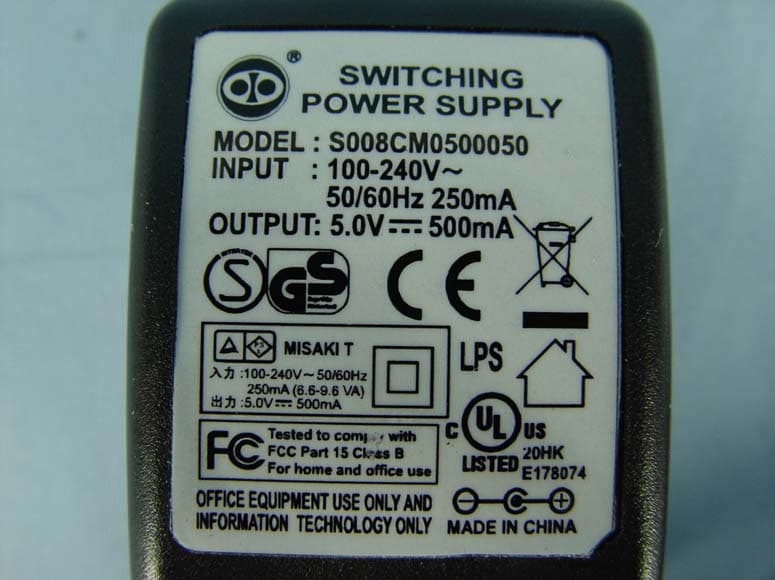
TEST PHOTOGRAPHS / DIAGRAMS ANNEX B 56S030132/01 EUT PHOTOGRAPHS EUT – DC Battery Removed EUT Housing – Internal View TEST PHOTOGRAPHS / DIAGRAMS ANNEX B 56S030132/01 EUT PHOTOGRAPHS EUT AC/DC Power Adapter – Top View EUT AC/DC Power Adapter – Bottom View TEST PHOTOGRAPHS / DIAGRAMS ANNEX B 56S030132/01 EUT PHOTOGRAPHS EUT PCB - Top View TEST PHOTOGRAPHS / DIAGRAMS ANNEX B 56S030132/01 EUT PHOTOGRAPHS EUT PCB - Bottom View
Operational Description
Frequency Hopping Spread Spectrum (FHSS) Descriptions 1. Output Power and Channel Separation of a Bluetooth Device in the Different Operating Modes The different operating modes (data-mode, acquisition-mode) of a Bluetooth device don't influence the output power and the channel spacing. There is only one transmitter, which is driven by identical input parameters concerning these two parameters. Only a different hopping sequence will be used. For this reason, the RF parameters in one op-mode are sufficient. 2. Frequency Range of a Bluetooth Device The maximum frequency of the device is 2402MHz - 2480 MHz. This is according the Bluetooth Core Specification V 1.1. 3. Co-Ordination of the Hopping Sequence in Data Mode to Avoid Simultaneous Occupancy by Multiple Transmitters Bluetooth units, which want to communicate with other units, must be organized in a structure called piconet. This piconet consist of maximum 8 Bluetooth units. One unit is the master the other seven are the slaves. The master co-ordinates frequency occupation in this piconet for all units. As the master hop sequence is derived from it's BD address which is unique for every Bluetooth device, additional masters intending to establish new piconets will always use different hop sequences. 4. Example of a Hopping Sequence in Data Mode: Example of a 79 hopping sequence in data mode: 40, 21, 44, 23, 42, 53, 46, 55, 48, 33, 52, 35, 50, 65, 54, 67, 56, 37, 60, 39, 58, 69, 62, 71, 64, 25, 68, 27, 66, 57, 70, 59, 72, 29, 76, 31, 74, 61, 78, 63, 01, 41, 05, 43, 03, 73, 07, 75, 09, 45, 13, 47, 11, 77, 15, 00, 64, 49, 66, 53, 68, 02, 70, 06, 01, 51, 03, 55, 05, 04 5. Equally Average Use of Frequencies in Data Mode and Short Transmissions The generation of the hopping sequence in connection mode depends essentially on two input values: 1. LAP/UAP of the master of the connection 2. Internal master clock The LAP (lower address part) is the 24 LSB's of the 48 BD-ADDRESS. The BD ADDRESS is an unambiguous number of every Bluetooth unit. The UAP (upper address part) are the 24 MSB's of the 48 BD-ADDRESS. The internal clock of a Bluetooth unit is derived from a free running clock, which is never adjusted and is never turned off. For synchronization with other units, only the offsets are used. It has no relation to the time of the day. Its resolution is at least half the RX/TX slot length of 312.5IJs. The clock has a cycle of about one day (23h30). In most case it is implemented as a 28-bit counter. For the deriving of the hopping sequence the entire LAP (24 bits), 4 LSB's (4 bits) (Input 1) and the 27 MSB's of the clock (Input 2) are used. With this input values different mathematical procedures (permutations, additions, XOR-operations) are performed to generate the sequence. This will be done at the beginning of every new transmission. Regarding short transmissions, the Bluetooth system has the following behavior: The first connection between the two devices is established, a hopping sequence is generated. For transmitting the wanted data, the complete hopping sequence is not used and the connection ends. The second connection will be established. A new hopping sequence is generated. Due to the fact that the Bluetooth clock has a different value, because the period between the two transmission is longer (and it cannot be shorter) than the minimum resolution of the clock (312.5 μs). The hopping sequence will always differ from the first one. 6. Receiver Input Bandwidth, Synchronization and Repeated Single or Multiple Packets The input bandwidth of the receiver is 1 MHz. In every connection, one Bluetooth device is the master and the other one is the slave. The master determines the hopping sequence (see section 5). The slave follows this sequence. Both devices shift between RX and TX time slot according to the clock of the master. Additionally the type of connection (e.g. single or multi-slot packet) is set up at the beginning of the connection. The master adapts its hopping frequency and its TX/RX timing is according to the packet type of the connection. Also, the slave of the connection uses these settings. Repeating of a packet has no influence on the hopping sequence. The hopping sequence generated by the master of the connection will be followed in any case. That means, a repeated packet will not be send on the same frequency, it is send on the next frequency of the hopping sequence. 7. Dwell Time in Data Mode The dwell time of 0.3797s within a 30 seconds period in data mode is independent from the packet type (packet length). The calculation for a 30 seconds period is as follows: Dwell time = time slot length * hop rate / number of hopping channels *30s Example for a DH1 packet (with a maximum length of one time slot) Dwell time = 625 IJs * 1600 1/s /79 * 30s = 0.3797s (in a 30s period) For multi-slot packet the hopping is reduced according to the length of the packet. Example for a DH5 packet (with a maximum length of five time slots) Dwell time = 5 * 625 μs * 1600 * 1/5 *1/s / 79 * 30s = 0.3797s (in a 30s period) This is according the Bluetooth Core Specification V 1.1 for all Bluetooth devices. Therefore, all Bluetooth devices comply with the FCC dwell time requirement in the data mode. This was checked during the Bluetooth Qualification tests. The Dwell time in hybrid mode is approximately 2.6ms (in a 12.8s period). 8. Channel Separation in Hybrid Mode The nominal channel spacing of the Bluetooth system is 1 MHz independent of the operating mode. The maximum "initial carrier frequency tolerance" which is allowed for Bluetooth is f center = 75 kHz. This was checked during the Bluetooth Qualification tests (Test Case: TRM/CA/07-E) for three frequencies (2402MHz, 2441MHz, 2480 MHz). 9. Derivation and Examples for a Hopping Sequence in Hybrid Mode For the generation of the inquiry and page hop sequences the same procedures as described for the data mode are used (see section 5), but this time with different input vectors: ♦ For the inqu…
Text truncated - open the document above for the full version.
Test Report
TEST REPORT Your Ref:Date: 15 March 2003 Our Ref: 56S030132/01 Page: 1 of 39 DID: 6885 1448 Fax: 6777 6409 LA-2001-0212-A LA-2001-0213-F LA-2001-0214-E LA-2001-0215-B LA-2001-0216-G LA-2001-0217-G The results reported herein have been performed in accordance with the laboratory’s terms of accreditation under the Singapore Accreditation Council - Singapore Laboratory Accreditation Scheme PSB Corporation • Testing Group • 1 Science Park Drive Singapore 118221 • Fax 6775 9725 • Email [email protected] • Website www.psbcorp.com Your product quality and safety mark NOTE: This Report is issued subject to the “Terms and Conditions Governing Technical Services” set out in the “Request for Technical Services” form. The terms and conditions governing the issue of this report are set out overleaf. FORMAL REPORT ON TESTING IN ACCORDANCE WITH FCC Part 15C : 2002 OF A BLUE PENDANT BLUETOOTH HEADSET [ MODEL : BP 100 ] [ FCC ID : QY9-AVBP ] TEST FACILITY Telecoms & EMC, Testing Group, PSB Corporation Pte Ltd 1 Science Park Drive, Singapore 118221 FCC REG. NO. 90937 (3m & 10m OATS) 99142 (10m Anechoic Chamber) 871638 (5m Anechoic Chamber) IND. CANADA REG. NO. IC 4257 (10m Anechoic Chamber) PREPARED FOR Ms Anitha Addvalue Communications Pte Ltd 750D Chai Chee Road #03-03 Technopark @ Chai Chee Singapore 469004 Tel : +65 6244 4828Fax : +65 6242 4555 JOB NUMBER 56S030132 TEST PERIOD 25 Feb 2003 – 03 Mar 2003 PREPARED BYAPPROVED BY ____________________ Lim Cher Hwee Engineer ____________________ Colin Gan Assistance Vice President April 2002Page 2 of 39 This Report is issued under the following conditions: 1. Results of the testing/calibration in the form of a report will be issued immediately after the service has been completed or terminated. 2. Unless otherwise requested, a report shall contain only technical results. Analysis and interpretation of the results and professional opinion and recommendations expressed thereupon, if required, shall be clearly indicated and additional fee paid for, by the Client. 3. This report applies to the sample of the specific product/equipment given at the time of its testing/calibration. The results are not used to indicate or imply that they are applicable to other similar items. In addition, such results must not be used to indicate or imply that PSB Corporation approves, recommends or endorses the manufacturer, supplier or user of such product/equipment, or that PSB Corporation in any way “guarantees” the later performance of the product/equipment. 4. The sample/s mentioned in this report is/are submitted/supplied/manufactured by the Client, PSB Corporation therefore assumes no responsibility for the accuracy of information on the brand name, model number, origin of manufacture, consignment or any information supplied. 5. Additional copies of the report are available to the Client at an additional fee. No third party can obtain a copy of this report through PSB Corporation, unless the Client has authorised PSB Corporation in writing to do so. 6. PSB Corporation may at its sole discretion add to or amend the conditions of the report at the time of issue of the report and such report and such additions or amendments shall be binding on the Client. 7. All copyright in the report shall remain with PSB Corporation and the Client shall, upon payment of PSB Corporation’s fees for the carrying out of the tests/calibrations, be granted a license to use or publish the report to the third parties subject to the terms and conditions herein, provided always that PSB Corporation may at its absolute discretion be entitled to impose such conditions on the license as it sees fit. 8. Nothing in this report shall be interpreted to mean that PSB Corporation has verified or ascertained any endorsement or marks from any other testing authority or bodies that may be found on that sample. 9. This report shall not be reproduced wholly or in parts and no reference shall be made by the Client to PSB Corporation or to the report or results furnished by PSB Corporation in any advertisements or sales promotion. 56S030132/01Addvalue Communications Pte LtdPage 3 of 39 Blue Pendant Bluetooth Headset [ Model: BP100 ] [ FCC ID: QY9-AVBP ] TABLE OF CONTENTS TEST SUMMARY PRODUCT DESCRIPTION SUPPORTING EQUIPMENT LIST EUT OPERATING CONDITION TEST RESULTS ANNEX A-TEST INSTRUMENTATION & GENERAL PROCEDURES ANNEX B-EUT PHOTOGRAPHS / DIAGRAMS ANNEX C-USER MANUAL, TECHNICAL DESCRIPTION, BLOCK & CIRCUIT DIAGRAMS ANNEX D-FCC LABEL & POSITION 56S030132/01Addvalue Communications Pte LtdPage 4 of 39 Blue Pendant Bluetooth Headset [ Model: BP100 ] [ FCC ID: QY9-AVBP ] TEST SUMMARY The product was tested in accordance with the customer's specifications. Test Results Summary FCC ParagraphsDescriptionsPass / Fail 15.207Conducted EmissionsPass 15.205Radiated Emissions (Restricted Band Requirements)Pass 15.209Radiated Emissions (Spurious Emissions)Pass Carrier Frequency SeparationPass 15.247 (a)(1) Spectrum Bandwidth (20dB Bandwidth Measurement)Pass Number of Hopping FrequenciesPass 15.247 (a)(1)(iii) Average Frequency Dwell TimePass 15.247 (b)(1)Maximum Peak PowerPass 15.247 (b)(4)Effective Isotropic Radiated Power (EIRP) RequirementsPass 15.247 (c)RF Conducted Spurious Emissions & Band Edge Compliance at the Transmitter Antenna Terminal Pass 15.247 (d)Peak Power Spectral DensityPass 1.1310Maximum Permissible ExposureN/A * see Note 3 Notes 1.Three channels as listed below, which respectively represent the lower, middle and upper channels of the equipment under test (EUT) were chosen and tested. For each channel, the EUT was configured to operate in the Bluetooth test mode Transmit Channel Frequency (GHz) Channel 02.402 Channel 392.441 Channel 782.480 2.All the measurements in section 15.247 were done based on conducted measurements. 3.As the typical distance between users and the EUT is less than 20cm, maximum exposure test is not applicable. Specific Absorption Rate (SAR) test is not required either as the maximum tran…
Text truncated - open the document above for the full version.
Test Setup Photos
56S030132/01Addvalue Communications Pte LtdPage 17 of 39 Blue Pendant Bluetooth Headset [ Model: BP100 ] [ FCC ID: QY9-AVBP ] TEST RESULTS Radiated Emissions Setup (Front View) Radiated Emissions Setup (Rear View) 56S030132 56S030132 56S030132/01Addvalue Communications Pte LtdPage 18 of 39 Blue Pendant Bluetooth Headset [ Model: BP100 ] [ FCC ID: QY9-AVBP ] TEST RESULTS FCC Part 15C (15.247(a)(1)) Carrier Frequency Separation Results The EUT shows compliance to the requirements of this section, which states the adjacent carrier frequencies must be separated by a minimum of 25kHz or the 20dB bandwidth of the hopping channel, whichever is greater. Adjacent ChannelsChannel Separation (MHz) 0 and 1 (2.402GHz and 2.403GHz)1.005 38 and 39 (2.440GHz and 2.441GHz)1.013 39 and 40 (2.441GHz and 2.442GHz)1.013 77 and 78 (2.479GHz and 2.480GHz)1.005 Please refer to the attached Plots 1 - 4 for details. Tested By: AL Carrier Frequency Separation Measurement Test Setup 56S030132/01Addvalue Communications Pte LtdPage 9 of 39 Blue Pendant Bluetooth Headset [ Model: BP100 ] [ FCC ID: QY9-AVBP ] TEST RESULTS Conducted Emissions Setup (Front View) Conducted Emissions Setup (Rear View) 56S030132/01Addvalue Communications Pte LtdPage 21 of 39 Blue Pendant Bluetooth Headset [ Model: BP100 ] [ FCC ID: QY9-AVBP ] TEST RESULTS FCC Part 15C (15.247(a)(1)) Spectrum Bandwidth (20dB Bandwidth Measurement) Results The EUT 20dB Bandwidth was tabulated as shown below. ChannelChannel Frequency (GHz)20dB Bandwidth (MHz) 02.4021.170 392.4411.170 782.4801.245 Please refer to attached Plots 5 - 7 for details. Tested By: AL Spectrum Bandwidth Measurement Test Setup
Contact Information
Applicant
PRABAKAR KUTTANISEERI(MANAGER - QUALITY ENGINEERING)
Technical Contact
MET Laboratories Inc.Christopher Harvey
[email protected]410-354-3300
914 W. Patapsco Avenue · Baltimore, Maryland · United States
Non-Technical Contact
MET Laboratories Inc.Marianne Bosley
[email protected]410-354-3300
Test Firm
TUV SUD PSB Pte LtdHarold Tan
Technical Specifications
| # | Rule Parts | Frequency Range | Power Output |
|---|---|---|---|
| 1 | 15C | 2.40 GHz - 2.48 GHz | 600.00 µW |
Other Applications from Addvalue Communications Pte Ltd
QY9-SB1BCP1K
Oct 01, 2007Bluetooth Handset
Equipment Class
DSS - Part 15 Spread Spectrum Transmitter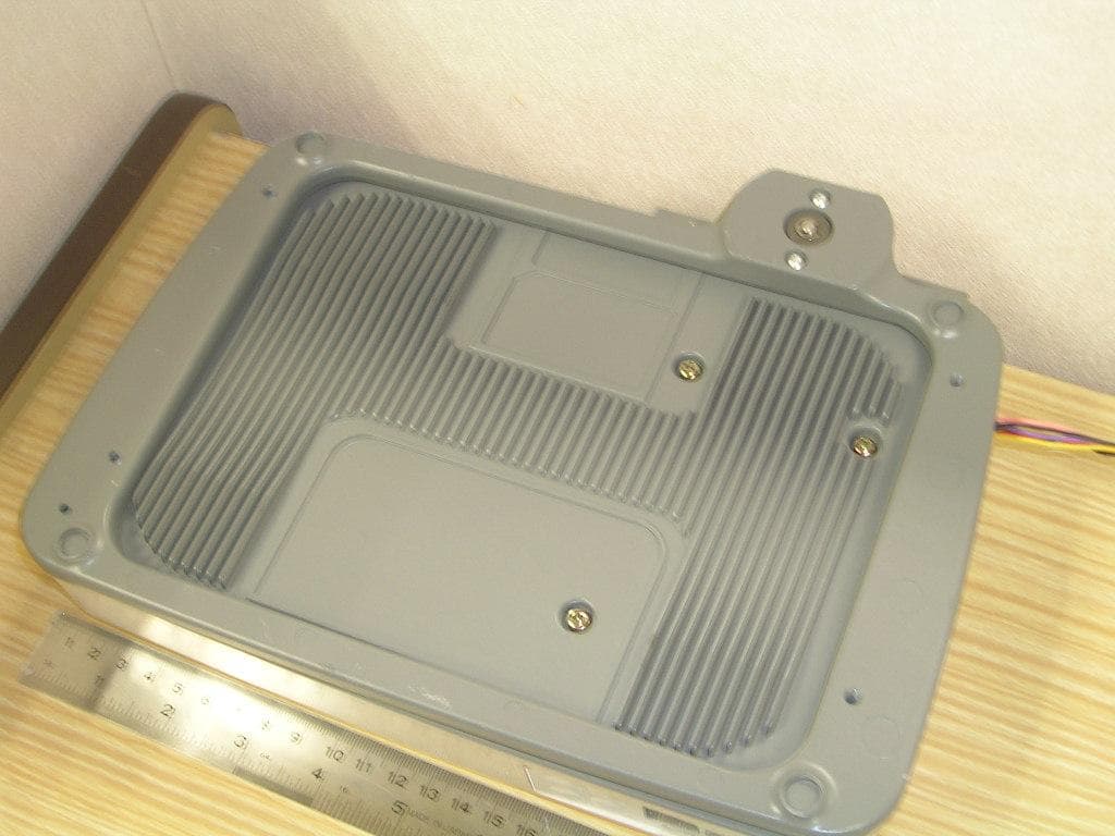
QY9-SABRE1WE
May 07, 2007WIDEYE SABRE 1
Equipment Class
DSS - Part 15 Spread Spectrum Transmitter
QY9-ACXA1C
Mar 25, 2004Audio Communicator
Equipment Class
DXX - Part 15 Low Power Communication Device Transmitter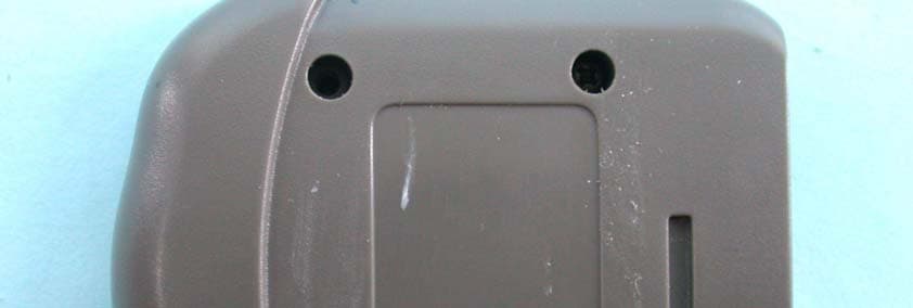
QY9-ACXA1B
Mar 24, 2004X Box Audio Communicator
Equipment Class
DXX - Part 15 Low Power Communication Device Transmitter