QYEHCRRDDE0207523Card Reader
ASK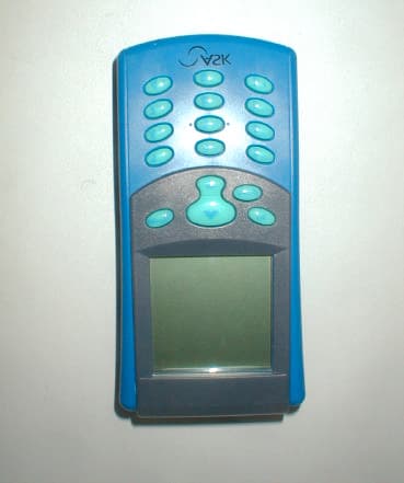
Click to zoom
Application Details
- Equipment Class
- DXX - Part 15 Low Power Communication Device Transmitter
- Date of Grant
- Jul 09, 2003
- Application Purpose
- Original Equipment
- Date of Application
- Jul 09, 2003
- Equipment Note
- Card Reader
- Frequency Range
- 13.56000000 - 13.56000000
- Company
- ASK
- Country
- France
Documents & Files
Document Text
Text extracted from the exhibit documents filed with the FCC. Open a document above to read the original.
Users Manual
RD-MU-03014-13 (Modifié SMEE) 1/19 10/07/03 DOCKING STATION HCC 100 USER MANUAL RD-MU-03014-13 (Modifié SMEE) 2/19 10/07/03 FCC Compliance Statements Class B Digital Device: This device complies with Part 15 of the FCC Rules. These limits are designed to provide a reasonable protection against harmful interferences in a residential installation. This equipment generates, uses and can radiate radio frequency energy and, if not installed and used in accordance with the instructions manual, may cause harmful interference to radio communications. However, there is no guarantee that interference will not occur in a particular installation. If this equipment does cause harmful interference to radio or television reception, which can be determined by turning the equipment off and on, the user is encouraged to try the correct interference by one of the following measures: - Reorient or relocate the receiving antenna. - Increase the separation between the equipment and receiver. - Connect the equipment into an outlet on a circuit different from that to which the receiver is connected. - Consult an experienced radio/TV technician for help. Caution: The manufacturer is not responsible for any radio or television interference caused by unauthorized changes or modifications to this equipment. Unauthorized changes or modifications could void the user’s authority to operate this equipment. Compliance accessories: The accessories associated with this equipment are: shielded USB cable with ferrite tube (normally supplied with the HCC 100 and attached to it). These accessories are required to be used in order to ensure compliance with the FFC rules. CE Compliance statement The ASK HCC 100 docking station is in conformity with European requirements, this product has been assessed to the following standard: EN 55022 / CISPR22 Class B EN 55024 / CISPR 24 EN 60950-1 / IEC 60950-1 RD-MU-03014-13 (Modifié SMEE) 3/19 10/07/03 Table of contents 1 – FIRST USE 4 1.1 Unpacking 4 1.2 Docking station overview 4 1.3 Docking station opening 6 1.4 Grouping docking stations 7 1.5 Using docking station bay (X6) 8 2 – BATTERY RECHARGING 9 3 – TECHNICAL FEATURES 10 RD-MU-03014-13 (Modifié SMEE) 4/19 10/07/03 1 – First use 1.1 Unpacking Check in packaging box if following items are present: - 1 HCC 100 - 1 USB cable 1.2 Docking station overview The HCC 100 docking station performs the following functions: - Physical support of the terminal - Battery recharging - Interface for exchange of information between the terminal and the concentrator by USB link. It performs USB1.1 to 115.2 kb/s serial link adaptation between PC and HCR. It features Green / Orange / Red Led battery charge indicator. Side view: The docking station has four adhesive feet, different holes enable setting of the terminal on a horizontal or vertical support. Centering guide Precut parts Rubber foot RD-MU-03014-13 (Modifié SMEE) 5/19 10/07/03 Top view : The recharging connector is situated deep inside the docking station, in the hand-held reader footprint. At the front side a light with different colours provides information about recharging state. The backside of the hand-held reader’s footprint includes a path for the strap. Rear view : Holes for wall installation and opening for cable are seen at the rear side of the docking station. light Connector Path for strap Hole for wall installation Cable opening RD-MU-03014-13 (Modifié SMEE) 6/19 10/07/03 1.3 Docking station opening The docking station is composed of two parts : the cover shell and the chassis They are maintained together by self-locking. Unlocking can be done by action on the top of the cover or on the bottom of the chassis. The way depends on the setting of the docking station (table top or wall). Operating : With a flat screwdriver, push successively on the internal locking ergot, while cover shell is pushed back Top opening : cutaway drawing Bottom opening : cutaway drawing Push back Push back screwdriver screwdriver Cover shell RD-MU-03014-13 (Modifié SMEE) 7/19 10/07/03 1.4 Grouping docking stations HCC shelves own male centring guide at the left and female centring guide at the right which allow the HCC positioning when two or more HCC are associated. Lateral precut footprint can be broken in order to offer a path for fixing screws. This way, docking stations can be tight with M4x12 screw and nut. Precut footprint Screw and nut between HCC RD-MU-03014-13 (Modifié SMEE) 8/19 10/07/03 1.5 Using docking station bay (X6) ASK can provide optional bays, they support up to 6 docking stations. These bays can easily be in juxtaposition, this allows the associated setting of several docking stations (6, 12, 18,...). The support can be either set on a wall or on a table Support RD-MU-03014-13 (Modifié SMEE) 9/19 10/07/03 2 – Battery recharging Before first use, the hand-held reader should be inserted in its docking station for a minimum of five hours for battery charging completion. The next reload will depend of the battery discharge. Internal battery use li-ion technology, that means it doesn’t have memory effect. The internal battery can be charged at any time, without wasting its capacity . IMPORTANT : Never turn OFF the PC when docking station is connected to USB port and while a hand-held reader is connected. The docking station should be connected to a computer via a USB port. No more connection is required. The docking station’s light should bright, three colors are possible : - Orange : docking station power is ON - Red : hand-held reader is charging. It shouldn’t be removed - Green : charging is over, reader can be removed Blinking on colors means the hand-held reader is exchanging data with the computer. Green light should bright without blinking for removing the reader from the docking station. Note : When reader is set on docking station, its power up is automatically launched and will remain so until recharging completion. MenuOK Annul 1 2 3 4 5 6 7 8 9 0 abc def ghi jkl mno pqrs tuv wxy…
Text truncated - open the document above for the full version.
Users Manual
RD-MU-02161-13 1/1 07/07/03 HAND-HELD READER HCR 800/805 USER MANUAL Menu OK Annul 1 2 3 4 5 6 7 8 9 0 abc def ghi jkl mno pqrs tuv wxyz # RD-MU-02161-13 2/19 07/07/03 FCC Compliance Statements This equipment has been tested and found to comply with the radiated limits for a Class B digital device, pursuant to Part 15 of the FCC Rules. These limits are designed to provide a reasonable protection against harmful interferences in a residential installation. This equipment generates, uses and can radiate radio frequency energy and, if not installed and used in accordance with the instructions, may cause harmful interference to radio communications. However, there is no guarantee that interference will not occur in a particular installation. If this equipment does cause harmful interference to radio or television reception, which can be determined by turning the equipment off and on, the user is encouraged to try the correct interference by one or more of the following measures: - Reorient or relocate the receiving antenna. - Increase the separation between the equipment and receiver. - Connect the equipment into an outlet on a circuit different from that to which the receiver is connected. - Consult the dealer or an experienced radio/TV technician for help. This device complies with Part 15 of the FCC rules. Operation is subject to the following two conditions. (1) This device may not cause harmful interferences. And (2) this device must accept any interference received, including interference that may cause undesired operation. The ASK HCR800/HCR805 readers were submitted and a grand of authorization received from the FCC as device under the intentional radiator requirements of Part 15, Subpart C. Caution: Any changes or modification not approved by ASK could void user’s authority to operate the equipment. CE Compliance statement The ASK HCR readers are in conformity with European requirements, this product has been assessed to the following standard: EN 300330 EN 301 489-3 EN 60950-1 / IEC 60950-1 RD-MU-02161-13 3/19 07/07/03 Table of contents 1 – FIRST USE 4 1.1 Unpacking 4 1.2 HCR 800 overview 4 1.3 Strap installation 5 1.4 Strap adjustment 6 1.5 Belt base using 6 2 – BATTERY RECHARGING 6 3 – SAM MODULES SETUP 7 4 – APPLICATIVE SOFTWARE LOADING 8 5 – USE 8 5.1 ON/OFF 8 5.1 Contactless card 8 5.2 Contact card 8 6 –TECHNICAL FEATURES 9 7 – TROUBLESHOOTING – AUTOTEST 10 RD-MU-02161-13 4/19 07/07/03 1 – First use 1.1 Unpacking Check in packaging box if following items are present: -1 hand-held reader -1 belt base -1 holding strap 1.2 HCR 800 /805 overview Menu OK Annul 1 2 3 4 5 6 7 8 9 0 abc def ghi jkl mno pqrs tuv wxyz # Graphic display 160 pl x 160 pl Antenna location ON/OFF key (press 3s.) Control leds Browser keys Alphanumeric Keys RD-MU-02161-13 5/19 07/07/03 Contact card slot Connector for battery charging x 6 screws for bottom case closure Holder strap HCR 800 made in France Type : DE-075-01 Serial 024401 ID label 1.3 Strap installation Insert the strap into the holder upper strap ring, then into the lower ring, after, bend back the two sides of the strap as shown in the following figure. RD-MU-02161-13 6/19 07/07/03 1.4 Strap adjustment The strap should be adjusted to the user’s hand. For that, it is necessary to move the two straps part (Velcro covered) in order to have the required space. 1.5 Using belt base Belt base should be locked on belt vertically from top to bottom. The HCR goes to belt base via the riveted button on the strap. Reader is inserted from bottom to top. For extracting, apply a pressure with one hand to the two lateral buttons of the base, with the other hand lift the hand- held reader up. 2 – Battery recharging Before first use, the HCR should be inserted in its base station for five hours minimum for battery charging completion. The next recharge will depend on the battery discharge. Internal battery uses li-ion technology, that means it doesn’t have memory effect. The internal battery can be charged at any time, without capacity waste. The docking station should be connected to a computer via an USB port. No other connection is required. The docking station’s light should bright, three colors are possible : - Orange : docking station power is ON MenuOK Annul 1 2 3 4 5 6 7 8 9 0 abc def ghi jkl mno pqrs tuv wxyz # Reader setup USB cable to PC Charging red light indicator RD-MU-02161-13 7/19 07/07/03 - Red : hand-held reader is charging. It shouldn’t be carried out - Green : charging is over, reader can be carried out Blinking on colors means the hand-held reader is exchanging data with the computer. Do not remove the reader from the docking station when led is blinking. Do not shut off the PC power supply when reader is set on dockingstation Note : When reader is set on docking station, its power up is automatically launched and will remain so until recharging completion. 3 – SAM modules setup For opening, flip over the hand-held reader. Screw off the six screws around the bottom part of the plastic case, then lift this part up. For this operation, the screwdriver type must be : Pozidriv N°1. SAM slots can be reached directly. Tree location are offered, the first one is JSIM 1(see figure below). First, SAM module must be gently inserted in the open door socket, then door should be locked. After operation, set again the bottom of the plastic case with the six screws. RD-MU-02161-13 8/19 07/07/03 4 – Applicative software loading Applicative software is loaded by PC computer while hand-held reader is set on docking station. Environment software installation CD (ART TOOLKIT) provides all the tools required for developing load applicative software. This CD ROM is delivered separately, please contact your local reseller for more information. 5 - Use 5.1 ON/OFF Hand-held reader is turned ON by pressing the menu key for 3 seconds. After that applicative software (user specific) is ready to run. The reader is turned OFF by pressing the menu key for 3 secondes. 5.1 Co…
Text truncated - open the document above for the full version.
Cover Letter(s)
June 26 th , 2003 CONFIDENTIALITY REQUEST Curtis-Straus LLC 527 Great Road Littleton, MA 01460 USA Re: Confidentiality request for a Low Power Communication Device FCC ID: QYEHCRRDDE0207523 Gentlemen, ASK requests, pursuant to 47CFR 0.459, post grant confidentiality for portions of the material contained in this application. The following document regarding this submission for FCC ID: QYEHCRRDDE0207523 be kept confidential 1. Schematic Diagram of HCR 800-805 (file: Schematic Diagram-HCR 800-805.pdf) 2. Block diagram of HCR 800-805 (file: Block Diagram- HCR 800-805.pdf) 3. Operational description of HCR 800-805 (file: Oper Descr- HCR 800-805.pdf) Specifically, these exhibits contain information relating to circuit function and complexity that could be of benefit to competitors. The material contains trade secrets and confidential information that ASK does not customarily release to the public and which is otherwise not generally available to the public. Regards, François MONTEIL R&D Director ASK Les Bouilles – 15, Traverse des Brucs F-06560 VALBONNE SOPHIA ANTIPOLIS - France
Cover Letter(s)
Response to TCB Findings Please confirm that HCR 800-805 has been tested in 3 orthogonal planes as it is a hand- held device Response: The HCR 800 was tested as a hand held device in position that maximised emission (3 planes checked). The HCC-100 manual needs to address the requirement to use the shielded USB cable with ferrite tube on it for compliance as seen in the internal pictures Response: Supplied, see the revised user manual for HCC-100 Page 2.
External Photos
FCC ID: QYEHCRRDDE0207523 Page 1/6 EXTERNAL PHOTOS OF TESTED EUT 1.1 HCR 800/805 with HCC 100 PHOTOS General view, HCR 800/805 reader with HCC 100 docking station (with USB cable) Rear view, HCR 800/805 reader with HCC 100 docking station (with USB cable) FCC ID: QYEHCRRDDE0207523 Page 2/6 Right view, HCR 800/805 reader with HCC 100 docking station (with USB cable) 1.2 HCR 800/805 PHOTOS Front view of HCR 800/805 reader FCC ID: QYEHCRRDDE0207523 Page 3/6 Bottom view of HCR 800/805 reader (interface connector) Top view of HCR 800/805 reader (antenna side) Right view of HCR 800/805 reader Left view of HCR 800/805 reader FCC ID: QYEHCRRDDE0207523 Page 4/6 Rear side of HCR 800/805 reader 1.3 HCC 100 PHOTOS General view of HCC 100 docking station FCC ID: QYEHCRRDDE0207523 Page 5/6 Rear view of HCC 100 docking station Top view of HCC 100 docking station FCC ID: QYEHCRRDDE0207523 Page 6/6 aazz Under view of HCC 100 docking station
ID Label/Location Info
FCC ID: QYEHCRRDDE0207523 Page 1/2 1 PRODUCT LABELING 1.1 FCC ID Label This is the copy of the label stuck on the product. Size is 40x30mm. Material is metallic polyester. Printing mode is thermal transfer. r HCR 800 made in France type : DE-02075-23 Serial 0314001 This device complies with Part 15 of the FCC rules. Operation is subject to the following two conditions: (1) this device may not cause harmful interferences, and (2) this device must accept any interference received, including interference that may cause undesired operation. FCC ID : QYEHCRRDDE0207523 HCC 100 made in France type : DE-02080-20 Serial 0306022 FCC ID : QYEHCRRDDE0207523 This device complies with Part 15 of the FCC rules. Operation is subject to the following two conditions: (1) this device may not cause harmful interferences, and (2) this device must accept any interference received, including interference that may cause undesired operation. 30 40 FCC ID: QYEHCRRDDE0207523 Page 2/2 1.2 Location of label on EUT Label is stuck on the rear side of the HCR 800/805 (see photo). Rear side of the HCR 800/805 reader Label is stuck on the under side of the HCC 100 (see photo). Under side of the HCR 800/805 reader
Internal Photos
FCC ID: QYEHCRRDDE0207523 Page 1/10 INTERNAL PHOTOS OF TESTED EUT 1.1 Internal photos of HCR 800/805 HCR 800/805 reader (Rear cover removed) HCR 800/805 reader (without front and rear plastic housing) FCC ID: QYEHCRRDDE0207523 Page 2/10 HCR 800/805 reader (Antenna board) HCR 800/805 reader (Antenna connectors) HCR 800/805 reader (Battery connector) FCC ID: QYEHCRRDDE0207523 Page 3/10 HCR 800/805 reader (Plastic housing – Front part with keyboard) HCR 800/805 reader (Plastic housing – Front part without keyboard) FCC ID: QYEHCRRDDE0207523 Page 4/10 HCR 800/805 reader (Keyboard) HCR 800/805 reader (Keyboard) FCC ID: QYEHCRRDDE0207523 Page 5/10 1.2 PCB photos of HCR 800/805 HCR 800/805 reader (Main board with display and antenna board) HCR 800/805 reader (Main board without display and antenna board) FCC ID: QYEHCRRDDE0207523 Page 6/10 HCR 800/805 reader (Main board – Smart card connectors side) HCR 800/805 reader (Main board without smart card connectors) FCC ID: QYEHCRRDDE0207523 Page 7/10 HCR 800/805 reader (Display board) HCR 800/805 reader (Antenna board) HCR 800/805 reader (Antenna board) FCC ID: QYEHCRRDDE0207523 Page 8/10 1.3 Internal photos of HCC 100 docking station HCC 100 docking station (Lower part of plastic housing removed) HCC 100 docking station (Lower part of plastic housing) FCC ID: QYEHCRRDDE0207523 Page 9/10 HCC 100 docking station (Upper part of plastic housing) FCC ID: QYEHCRRDDE0207523 Page 10/10 1.4 PCB photos of HCC 100 docking station HCC 100 docking station (PCB – Interface connector side) HCC 100 docking station (PCB – USB connector side)
Test Report
Actions Mesures ZI des Blanchisseries - 38500 VOIRON - Tél. 04 76 65 76 50 - FAX 04 76 66 18 30 S.A. au capital de 152 449,02 € / R.C. de Grenoble B 329 901 888 / SIRET 329 901 888 00035 / code APE 332 B / n°TVA :FR29 329 901 888 This test report applies only on equipment described hereafter. Proposal number: 200301-2131 Date........................................: March 3 rd to 6 th and 25 th , 2003 Location..................................: SMEE Actions Mesures Laboratory - 38 VOIRON Performed by...........................: Laurent CHAPUS Customer................................: ASK (Represented by Mr. LOGNON) Les Bouillides – 15, Traverse des Brucs 06560 Valbonne Sophia Antipolis FRANCE Product...................................: HCR 800 / HCR 805 With docking station HCC 100 Type of test.............................: Radiated and Conducted Emission Test Applied standards....................: ANSI C63-4 (1992+2000) CISPR22 (1997) + A1 (2000) 47 CFR Part 15 Subpart B and Subpart C Result of tests.........................: Samples tested in configuration and description presented in this test report comply with prescriptions and limits of FCC Part 15, in radiated and conducted emissions. The reproduction of this test report is authorized only under its entire form. This report contents 19 pages. Written by...............................: Laurent CHAPUS Date : June 25th, 2003 Signature Approved by.............................: Jean-Pierre ORY EMC TEST REPORT Nr 2769-FCC FCCID : QYEHCRRDDE0207523 Nr 2769-FCC March 3rd to 6th and 25th, 2003 page 2 /19 1. System test configuration 1.1. Justification The system was configured for testing in a typical fashion (as a customer would normally use it). The HCR 800/805 is an intentional radiator when it is used as a contactless smartcard reader and is subject to the regulations of the Part 15, Subpart C. It can be also used as a peripheral device when the collected and stored data are transferred from the handheld reader to a computer with the USB interface of the HCC 100 docking station (unintentional radiator, coupler circuit is off in this case). 1.2. HARDWARE IDENTIFICATION: * Equipment Under Test (EUT): HCR 800 / HCR 805 sn: 0306001 or 0306038 With USB docking station HCC 100 sn: Proto • Configuration : The HCR 800 / HCR 805 is configured for the MIFARE® cryptography. (Equipment in this case is named HCR 805) • Input/output on HCR 800/805: - Interface connector HCR 800/805 to the HCC100 docking station • Input/output on HCC 100 docking station: - Interface connector with the HCR 800/805 - USB cable, shielded, fixed on the equipment: 2m • Frequencies : FREQUENCY SOURCE USE CPU and peripherals (HCR 800/805) 22,1184MHz Oscillator Main clock frequency for ARM microprocessor 32,768KHz Quartz Real Time Clock 10MHz Quartz LCD display main clock Coupler (HCR 800/805) 27,120MHz Oscillator Main clock frequency for RF treatments, FPGA clock 22,1184MHz Microcontroller Microcontroller internal frequency 13,56MHz FPGA Carrier frequency and digital filters 9,04MHz FPGA SAM main clock source 4,52MHz SAM electrical interface, FPGA SAM clock source 3,6864MHz Resonator Microcontroller 847,500KHz Contactless card sub- carrier, FPGA FPGA internal treatments 423,750KHz FPGA FPGA internal treatments 211,875KHz FPGA FPGA internal treatments 105,937KHz FPGA, RF data rate FPGA internal treatments FCCID : QYEHCRRDDE0207523 Nr 2769-FCC March 3rd to 6th and 25th, 2003 page 3 /19 Docking station (HCC 100) 6MHz Resonator USB/RS232 chip main clock • Equipment information : Radiated fundamental frequency of the HCR800/805 is 13.56MHz 1.3. Auxiliaries The FCC IDs for all equipment, plus description of all cables used in the tested system are: Trade Mark – Model Number (Serial number) FCC ID Description Cable description ASK – HCR 800 / HCR 805 (1) (Sn : 0306001) QYEHCRRDDE0 207523 Handheld contactless reader No cable ASK – HCC 100 (1) (Sn : Proto) QYEHCRRDDE0 207523 USB Docking station for HCR 800/805 reader USB shielded cable (fixed on the equipment) HEWLETT PACKARD Vectra VLI8 PIII-500 P/N: D7963A (sn: FR94020533) (2) DOC Personnel computer All data cables are shielded. Power cable unshielded. HEWLETT PACKARD P/N: D2846 (sn JP74001000) (2) DOC 21" color monitor Shielded video cable with ferrites at each end. Power cable unshielded. HEWLETT PACKARD P/N: C4734-60111 (sn: M971168931) (2) GYUR38SK Keyboard Shielded cable Microsoft X04-72167 (sn: 9916996-5) (2) DOC Mouse Shielded cable HEWLETT PACKARD Deskjet 895 Cxi (sn: MY9761915S) (2) DOC Parallel printer HP 24542D shielded parallel cable DC power cable unshielded HEWLETT PACKARD 48GX (sn: ID83802369) (2) None Serial calculator Shielded serial cable LABTEC LT-100 (sn: none) (2) None Headset Stereo audio cable TELEX Model 700 373 000A (2) None Microphone Stereo audio cable ASK – C.Ticket ISO 14443-2-3 Mode A and mode B (3) None Contactless paper ticket - (1): Equipment under test (2): Equipment used for test of the HCR 800/805 with docking station HCC 100. (3): Equipment used for the test of the HCR 800/805 reader alone. 1.4. Equipment modifications None. FCCID : QYEHCRRDDE0207523 Nr 2769-FCC March 3rd to 6th and 25th, 2003 page 4 /19 1.5. EUT Exercise software The EUT exercise program used during radiated and conducted testing was designed to exercise the HCR 800/805 in a manner similar to a typical use. Communication mode A and B (contactless reader) of the standard ISO/IEC 14443-2 are tested. The inboard software used during the evaluation of the HCR 800/805 alone permits the emission with mode A or B modulation or an emission without modulation. While testing the HCR 800/805 with the docking station HCC 100, a data file of 0.5Mo is transferred from the computer to the reader through the USB link. Software used is ZOC-PRO.exe (V4.10 – USB to serial port emulator software), running under windows 98. The HCR 800/805 is in a maintenance mode in this case. 1.6. Special accessories The USB interface cable used for compliance t…
Text truncated - open the document above for the full version.
Test Setup Photos
FCC ID: QYEHCRRDDE0207523 Page 1/3 CONDUCTED AND RADIATED MEASUREMENT PHOTO 1.1 Conducted emission for HCC 100 docking station test Front view Rear view Detail view FCC ID: QYEHCRRDDE0207523 Page 2/3 1.2 Radiated emission for HCC 100 docking station test Front View Rear View Detail view FCC ID: QYEHCRRDDE0207523 Page 3/3 1.3 Radiated emission for HCR 800/805 test Front view Detail view
Contact Information
Applicant
Laurent LOGNON(Hardware Engineer)
Test Firm
LCIE Sud-EstJacques Lorquin
Technical Specifications
| # | Rule Parts | Frequency Range | Power Output |
|---|---|---|---|
| 1 | 15C | 13.56 MHz - 13.56 MHz | - |
Other Applications from ASK
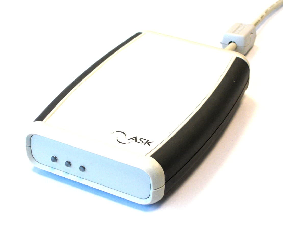
QYERDR41X
Feb 27, 2006USB Card Reader
Equipment Class
DXX - Part 15 Low Power Communication Device Transmitter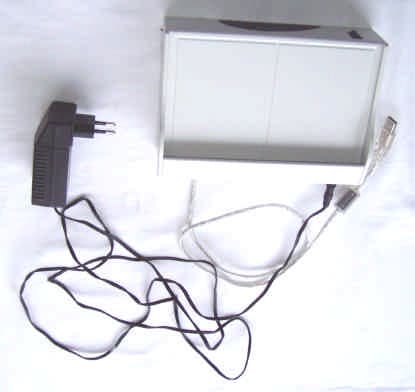
QYELDB3-RDDE05078
Jul 19, 2005Tag Reader
Equipment Class
DXX - Part 15 Low Power Communication Device Transmitter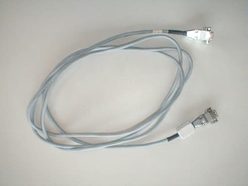
QYELDB2-RDDE03082
Jun 23, 2003Tag Reader
Equipment Class
DXX - Part 15 Low Power Communication Device Transmitter