QYERDR41XUSB Card Reader
ASK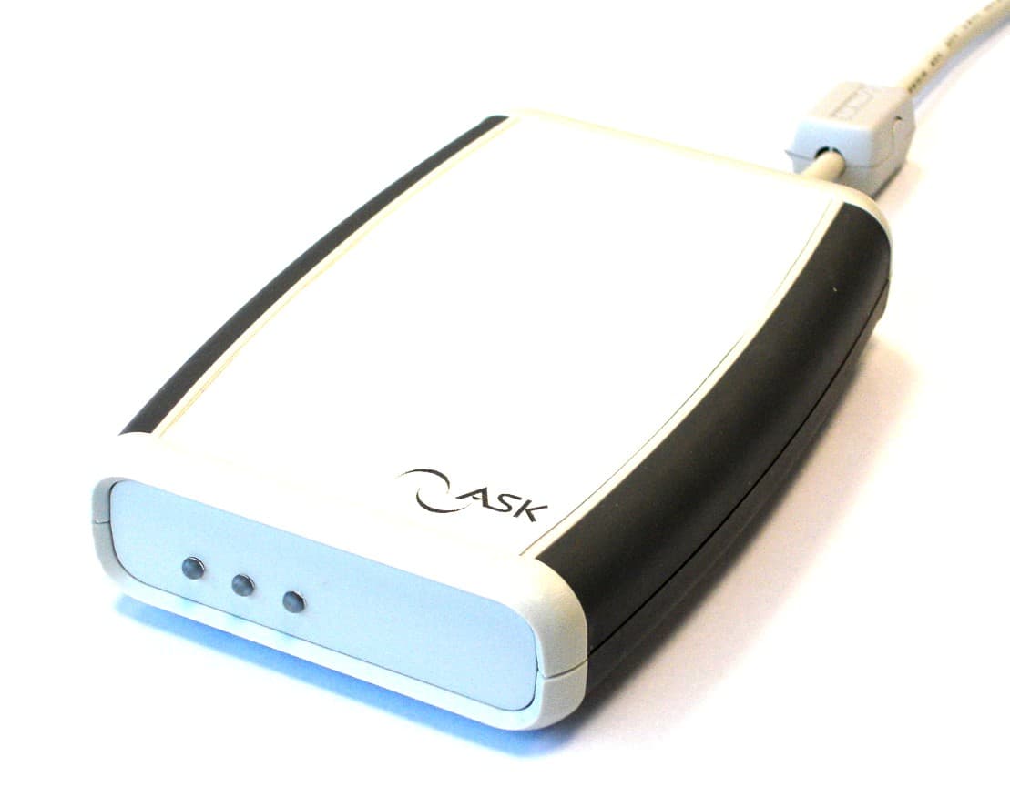
Click to zoom
Application Details
- Equipment Class
- DXX - Part 15 Low Power Communication Device Transmitter
- Date of Grant
- Feb 27, 2006
- Application Purpose
- Original Equipment
- Date of Application
- Feb 27, 2006
- Equipment Note
- USB Card Reader
- Frequency Range
- 13.56000000 - 13.56000000
- Company
- ASK
- Country
- France
Documents & Files
Document Text
Text extracted from the exhibit documents filed with the FCC. Open a document above to read the original.
Users Manual
ASK R&DRéf. : RD-MU-05179-10 1 / 13 ASK 2260 Route des CrêtesR&D001-Form1 06560 VALBONNE SOPHIA ANTIPOLIS Tel: 04 97 21 40 00 Fax: 04 92 38 93 21 USER MANUALRDR 417 RDR 417 USB contactless reader user manual ASK R&DRéf. : RD-MU-05179-10 2 / 13 ASK 2260 Route des CrêtesR&D001-Form1 06560 VALBONNE SOPHIA ANTIPOLIS Tel: 04 97 21 40 00 Fax: 04 92 38 93 21 TABLEOFCONTENTS 1SCOPE OF MANUAL3 2READER DESCRIPTION3 2.1Characteristics3 2.1.1Features3 2.1.2Main applications4 2.1.3Cards & tags supported4 2.2Architecture4 2.3Mechanical aspects5 2.3.1Attached USB cable definition6 2.3.2Adhesive cover film6 3READER SETUP7 3.1Unpacking and inspection7 3.2Installing the SAM in the reader7 3.3Reader connection to USB9 3.3.1Driver installation9 3.3.2Software9 4HOW TO USE THE READER10 4.1Contactless operation10 4.2Cleaning10 5STANDARD COMPLIANCE11 5.1FCC compliance statements11 5.2CE compliance statement11 5.3Annexe12 5.3.1Coupler board12 5.3.2Antenna board13 5.3.3Assembly13 USER MANUELRDR 417 USB contactless reader ASK R&DRéf. : RD-MU-050179-10 3 / 13 Copyright ASK SA - 2006 1SCOPEOFMANUAL This manual describes ASKRDR 417 contactless reader main features and setup information. This manual is intended for use by end users. Sam installation requires a “Philips” screwdriver for case opening. 2READERDESCRIPTION The RDR417 is a high speed, low cost, multi-standard, multi-application USB contactless reader. It supports all current ISO dual interface / contactless cards and contactless paper tickets. 2.1Characteristics The RDR417 reader is based on CPL407 coupler platform. 2.1.1Features • ISO 14443 A/B - ISO 15693 ISO/IEC 14443-2:2001/FPDAM 2 2004-03-17 • Contactless paper tickets • High powerclass 1 RF interface • Compatible with Windows 98 SE, Me, 2000, XP • PC/SC driver, ASK (dll) proprietary driver, or virtual COM driver available • High-speed communication: 106 Kb/s up to 847 Kb/s • Cryptographic security management with embedded SAM slot + Mifare® asic • USB 2.0 connection for PC-based applications • Powered via USB port (500 mA port) • CE Mark: EN300330, EN301 489-3, EN60950-1 • FCC class B part 15 • 3 control LEDs • 178 mm x 125 mm x 26 mm • Weight: 160 g • Operating temperature: 0°Cto 50°C USER MANUELRDR 417 USB contactless reader ASK R&DRéf. : RD-MU-050179-10 4 / 13 Copyright ASK SA - 2006 2.1.2Mainapplications • Identity • Banking • Logical / physical access control • PC/ workstation add-on 2.1.3Cards&tagssupported Mifare® standard, Mifare®4K, Mifare® Pro, Mifare Ultra Light, Mifare DESFIRE, Smart MX, SLE 55Rxx, SLE 66CL1605, SLE 66CLX320P, SR176, SRIX4K, Sharp B, all ASK cards and tickets. ICODE SLI. 2.2Architecture This diagram describes the general architecture of the RDR417 reader. The reader is an assembly of the ASK CPL407 USB coupler, and its dedicated local antenna ANT400. CPU USB interface SA M interf ace 5V DC converter Leds 6 MHz 3.6864 MHz FPGA 27.120 MHz osc R C 6 3 2 4.52 MHz 13.56 MHz RF emitter RF receiver 3.3V regulator 13.56 MHz m i n i B CPL407 ANT 400 RDR417 m i n i B U S B A 1m USB cable USER MANUELRDR 417 USB contactless reader ASK R&DRéf. : RD-MU-050179-10 5 / 13 Copyright ASK SA - 2006 2.3Mechanical aspects 7.57.5 3 9.5 diam2.8 117 79 F E R R I T E 24 Case: ABS light grey (RAL 7035) Soft side "grip" plastic: grey (RAL 7012) USER MANUELRDR 417 USB contactless reader ASK R&DRéf. : RD-MU-050179-10 6 / 13 Copyright ASK SA - 2006 2.3.1AttachedUSBcabledefinition Mini-B-to-USB Type A Length: 1m Current: 1.0A Contact resistance: 50mΩ max. Over-Mold: Gray Polyvinyl Chloride, UL 94V-0 Ferrite: Wurth 7427114 2.3.2Adhesivecoverfilm An adhesive cover film is added to the top case. It supports ASK logo. For volume order, it may be modified in order to support customer’s logo. Material is polycarbonate 250 μm, and adhesive 3M 468. USER MANUELRDR 417 USB contactless reader ASK R&DRéf. : RD-MU-050179-10 7 / 13 Copyright ASK SA - 2006 3READERSETUP 3.1Unpacking and inspection For end user unity packaging, the RDR 417 is delivered with an installation CD. It includes user manuals in *;pdf format, USB drivers, and a few demonstration software. 3.2Installing the SAM in the reader In most applications, one SAM (Security Application Module) is required. This component is provided separately, so to set a SAM, the plastic case should be opened. Caution: For SAM installation, it is mandatory to disconnect reader from USB port. For opening, unscrew the cover screw using a “Philips” head screwdriver. Open the case, and remove the lower case from the assembly. USER MANUELRDR 417 USB contactless reader ASK R&DRéf. : RD-MU-050179-10 8 / 13 Copyright ASK SA - 2006 Caution: In a first time, μSIM shape SAM must be gently inserted in the opened cover, then in a second time the cover should be closed and locked. Close and screw again the reader before use. USER MANUELRDR 417 USB contactless reader ASK R&DRéf. : RD-MU-050179-10 9 / 13 Copyright ASK SA - 2006 3.3Reader connection to USB Caution: The RDR417 is an USB powered reader. Because of its high RF power, it has to be imperatively connected to a native USB port of a computer, or a self powered USB hub able to deliver up to 500mA according to USB standard. To avoid improper operation: Prefer connection to a rear USB port directly handled by the motherboard. Avoid use of USB extension cable. Avoid replacement of the existing 1 meter USB A to miniB cable by a longer one. Note: Some PCMCIA USB2.0 extension boards for handheld computers are not able to deliver 500 mA. 3.3.1Driverinstallation Connect the reader to the proper USB port. Windows will detect it as a new device. Insert the installation CD, and follow the instructions on screen. You will be asked to choose between: Standard virtual COM driver, Card reader ASK (dll) proprietary driver, or PC/SC driver. Chosen driver will depend on the customer application software requirements. 3.3.2Software The RDR is delivered by default with an embedded application firmware called CSC which supports the ASK cards and C.ti…
Text truncated - open the document above for the full version.
Cover Letter(s)
February 28 th , 2006 CONFIDENTIALITY REQUEST Federal Communications Commission 7435 Oakland Mills Road Columbia, MD 21046 USA Curtis-Straus LLC 527 Great Road Littleton, MA 01460 USA Re: Confidentiality request for a Low Power Communication Device FCC ID: QYERDR41X Gentlemen, ASK requests, pursuant to 47CFR 0.459, post grant confidentiality for portions of the material contained in this application. The following documents regarding this submission for FCC ID: QYERDR41X shall be kept confidential 1.Schematic Diagrams of RDR417 (files: Schematic Diagram1-QYERDR41X.pdfandSchematic Diagram2-QYERDR41X.pdf) 2.Block diagram of RDR417 (file: Block Diagram-QYERDR41X.pdf) Specifically, these exhibits contain information relating to circuit function and complexity that could be of benefit to competitors. The material contains trade secrets and confidential information that ASK does not customarily release to the public and which is otherwise not generally available to the public. Regards, Olivier Parrault Hardware Engineer ASK 2405, routes des Dolines F-06560 VALBONNE SOPHIA ANTIPOLIS - France
Cover Letter(s)
Question: The block diagram shows two different chip options (RC632 and RC531) in the RF path. Please explain the differences between these chipsets and their possible effect on the RF characteristics. You can see on page 2 of the Test Report (chap 1.3) an explanation of the difference between RDR416 and RDR417 RDR416 : uses the RC531--> permits the reading of smartcards ISO 14443 mode A and mode B RDR417 : uses the RC632--> permits the reading of smartcards ISO 14443 mode A and mode B and ISO15693. All this different mode of reading have been examined for the compliance evaluation. Question: The voltages listed on Pg 12 of the report is not within +/- 15% of 5V. Please clarify. The USB standard specifies a voltage of 4.3V to 5.25Vdc. The product is powered by the USB voltage.
External Photos
FCC ID: QYERDR41X Page 1/3 1EXTERNAL PHOTOS OF TESTED EUT General view FCC ID: QYERDR41X Page 2/3 General view, front face and rear face. General view, left face and right face. FCC ID: QYERDR41X Page 3/3 General view, upper face and lower face.
ID Label/Location Info
FCC ID: QYERDR41X Page 1/2 1PRODUCT LABELING 1.1FCC ID Label This is the copy of the label stuck on the product. Size is 40x30mm. Material is metallic polyester. Printing mode is thermal transfer . FCC ID: QYERDR41X Page 2/2 1.2Location of label on EUT Label is stuck on the lower facethe product (see photo). Lower Face
Internal Photos
FCC ID: QYERDR41X Page 1/3 1INTERNAL PHOTOS OF TESTED EUT 1.1General view of equipment 1.2PCB view FCC ID: QYERDR41X Page 2/3 PCB view with ferrite square stuck on FPGAchip FCC ID: QYERDR41X Page 3/3 1.3General view of PCB (assembled)
Operational Description
FCC ID: QYERDR41X 1.GENERAL INFORMATION 1.1.Product description of RDR416 / RDR417 The RDR417 is a high speed, low cost, multi-standard, multi-application USB contactless reader. It supports all current ISO dual interface / contactless cards and contactless paper tickets. Characteristics The RDR417 reader is based on CPL407 coupler platform. Features • ISO 14443 A/B - ISO 15693 ISO/IEC 14443-2:2001/FPDAM 2 2004-03-17 • Contactless paper tickets • High power class 1 RF interface • Compatible with Windows 98 SE, Me, 2000, XP • PC/SC driver, ASK (dll) proprietary driver, or virtual COM driver available • High-speed communication: 106 Kb/s up to 847 Kb/s • Cryptographic security management with embedded SAM slot + Mifare® asic • USB 2.0 connection for PC-based applications • Powered via USB port (500 mA port) • CE Mark: EN300330, EN301 489-3, EN60950-1 • FCC Part 15, subpart C • 3 control LEDs • 178 mm x 125 mm x 26 mm • Weight: 160 g • Operating temperature: 0°C to 50°C Main applications • Identity • Banking • Logical / physical access control • PC/ workstation add-on Cards & tags supported Mifare® standard, Mifare®4K, Mifare® Pro, Mifare Ultra Light, Mifare DESFIRE, Smart MX, SLE 55Rxx, SLE 66CL1605, SLE 66CLX320P, SR176, SRIX4K, Sharp B, all ASK cards and tickets. ICODESLI. FCC ID: QYERDR41X Mechanical aspects Case: ABS light grey (RAL 7035) Soft side "grip" plastic: grey (RAL 7012) 7.57.5 3 9.5 diam 2.8 117 79 F E R R I T E 24 FCC ID: QYERDR41X Attached USB cable definition Mini-B-to-USB Type A Length: 1m Current: 1.0A Contact resistance: 50mΩ max. Over-Mold: Gray Polyvinyl Chloride, UL 94V-0 Ferrite: Wurth 7427114 Adhesive cover film An adhesive cover film is added to the top case. It supports ASK logo. For volume order, it may be modified in order to support customer’s logo. Material is polycarbonate 250 μm, and adhesive 3M 468. 1.2.Related Submittal(s) / Grant(s) All host equipment used in the test configuration are FCC granted, when relevant. 1.3.Tested System Details The FCC IDs for all equipment, plus description of all cables used in the tested system are : Trade Mark – Model Number (Serial number) FCC IDDescriptionCable description ASK – RDR417 (1) (Sn : 05520005) QYERDR41XUSB contactless reader USB cable, shielded with ferrite clip on reader side. DELLLatitude D600 TAG: 9VH931J E2K24CLNSPersonnel computer (Laptop) Power cables unshielded. USB shielded ASK – C.Ticket or samartcard ISO 14443-2-3 (Mode A and mode B) ISO 15693 None Contactless paper ticket and smartcard - (1): Equipment under test 1.4.Test Methodology Both conducted and radiated testing were performed according to the procedures in ANSI C63.4-2003, FCC Part 15 Subpart C. Radiated testing was performed at an antenna to EUT distance of 10 meters (F<30MHz) and 3m (F>30MHz). During testing, all equipment’s and cables were moved relative to each other in order to identify the worst case set-up. 1.5.Test facility Tests have been performed on December 28 th and 29 th , 2005. This test facility has been fully described in a report and accepted by FCC as compliant with the radiated and AC line conducted test site criteria in ANSI C63.4-2003 in a letter dated July 14, 2005 (registration number 94821). This test facility has also been accredited by COFRAC (French accreditation authority for European union test lab accreditation organization) according to NF EN ISO/IEC 17025, accreditation number 1-1633 as compliant with test site criteria and competence in 47 CFR Part 15/ANSI C63.4 and EN55022/CISPR22 norms for 89/336/EEC European EMC Directive application.All pertinent data for this test facility remains unchanged.
Test Report
This test report applies only on equipment described hereafter. Proposal number: 200512-2878 Date.........................................:December 27 th and 28 th , 2005 Location....................................: LCIE ZI des Blanchisseries 38500 VOIRON - France Performed by............................:Laurent CHAPUS Customer..................................:ASK (Representedby Mr. PARRAULT) 2405, route des Dolines 06560 SOPHIA ANTIPOLIS FRANCE Product.....................................: RDR 416/417 Type of test..............................: Radiated and Conducted Emission Test Applied standards.....................:ANSI C63-4 (2003) 47 CFR Part 15 Subpart C Result of tests.........................: Sample tested in configuration and description presented in this test report complieswith prescriptions and limits of FCC Part 15, subpart C, in radiated and conducted emissions. The reproduction of this test report is authorized only under its entire form. This report contents 14pages. Written by.................................:Laurent CHAPUS Date: February28th, 2006Signature Approved by.............................:Jacques LORQUIN EMC TEST REPORT Nr 3634-A1-FCC FCCID : QYERDR41X Nr3634-A1-FCCDecember27th and28th, 2005page 2 /14 1. System test configuration 1.1. Justification The system was configured for testing in a typical fashion (as a customer would normally use it). The RDR416 / RDR417is an intentional radiator as it is used as a contactless smartcard readerand is subject to the regulations of the Part 15, Subpart C. 1.2. HARDWAREIDENTIFICATION: * Equipment Under Test (EUT):RDR417 sn: 05520005 Configuration : The RDR 417is configured for the MIFARE® cryptography, ISO 14443 A or B and ISO 15693 standards using the RC632 chip. (Version without ISO 15693 is called RDR 416, using RC531 chip). Input/output on RDR 417: - USB interface shielded cable, fixed on the equipment: 1m (with ferrite clamp on EUT’s side) Frequencies : FREQUENCY SOURCEUSE 27,120MHzOscillatorMain clock frequency for RF treatments, FPGA clock 22,1184MHzMicrocontrollerMicrocontroller internal frequency 13,56MHzFPGACarrier frequency and digital filters 4,52MHzSAM electrical interface, FPGA SAM clock source 3,6864MHzResonatorMicrocontroller 847,500KHzContactless card sub- carrier RC632internal treatments 105,937KHzRF basic data rate RC632internal treatments 6MHzResonatorUSB chip main clock (Max data rate: 12MBit/s) Equipment information : Radiated fundamental frequencyof the RDR416/417is 13.56MHz Power input voltage: 5V from USB port FCCID : QYERDR41X Nr3634-A1-FCCDecember27th and28th, 2005page 3 /14 1.3. Auxiliaries The FCC IDs for all equipment, plus description of all cables used in the tested system are: Trade Mark – Model Number (Serial number) FCC IDDescriptionCable description ASK – RDR417 (1) (Sn : 05520005) QYERDR41XUSB contactless reader USB cable, shielded with ferrite clip on reader side. DELL Latitude D600 TAG: 9VH931J E2K24CLNSPersonnel computer (Laptop) Power cables unshielded. USB shielded ASK – C.Ticket or smartcard ISO 14443-2-3 (Mode A and mode B) ISO 15693 None Contactless paper ticketand smartcard - (1): Equipment under test 1.4. Equipment modifications None. 1.5. EUT Exercise software The EUT exercise program used during radiated and conducted testing was exercised the RDR 417in a manner similar to a typical use, excepted thatthe RF field is ON permanently with smartcard readings. Smartcards for mode A, B and ISO15693 are tested. PC Software used: POOLING V4.07b.EXE or ASK-MONITOR.EXE 1.6. Special accessories The USB interface cable used for compliance testing is shielded as normally supplied. The equipment is supplied with a ferrite clamp on the USB cable (Ferrite type WE 7427114) All these cables are normally recommended to be used with the product. 1.7. I/O cables Cables used for the test of the RDR 417: - 1x USB cable, shielded:1m - 1x AC power cord(PC): 1.8m 2. Radiated emission data 2.1. SET-UP The EUT is placed on a non-conducting table of 80cm height. FCCID : QYERDR41X Nr3634-A1-FCCDecember27th and28th, 2005page 4 /14 er Radiated emission test setup Equipment configuration and running mode: A contactless smartcard or paper ticket (mode A or mode B or ISO15693) is placedon the top side of the reader. The installation of EUT is identical for pre-characterization measurement in a 3 meters full anechoic chamber and for measures on a 3 meters Open site. 2.2. TESTEQUIPMENT Test equipment up to 1GHz on 3/10 meters open site: EquipmentCompany ModelSerial Spectrum AnalyzerHP8568B 2732A04155 Quasi-Peak adapterHP85650A2811A01134 RF Pre-selectorHP85685A2837A00784 Biconical AntennaEMCO3104C9401-4636 Log Periodic AntennaEMCO31462178 Spectrum AnalyzerHP8593E3409u00537 Loop antennaElectro-metricsEM-6879690234 AmplifierHP8447F H643113A06394 OATS EMCO-1050, 6 meters height antenna mast & EMCO-1060, 3 meters diameter Turntable. A 3 or 10 meters Open site located in LCIE- Voiron (FRANCE). Pre-scan, test equipment up to 1GHz: EquipmentCompany ModelSerial EMC Analyzer HP8591EM3536A00384 AmplifierHP8447F H643113A06394 Antenna (30MHz-1GHz)CHASECBL6111A1628 Loop antenna Electro-metricsEM-6879690234 FCCID : QYERDR41X Nr3634-A1-FCCDecember27th and28th, 2005page 5 /14 2.3. TEST SEQUENCE AND RESULTS 2.3.1.Pre-characterization at 3 meters [9kHz-30MHz] A pre-scan of all the setup has been performed in a 3 meters full anechoic chamber. The distance between EUT and antenna is 3 meters. Pre-characterization is performed in vertical (V) polarization and the loop antenna position was rotated during the test for maximized the emission measurement. Frequency band investigated is 9kHz to 30MHz. See below graph examples between 150MHz to 30MHz: (No frequency observed between 9kHz to 150KHz) (RBW = 9kHz, VBW = 30kHz) Result for 150MHz to 30MHz (Marker n°1 is 13.56MHz) 2.3.2.Pre-characterization at 3 meters [30MHz-1GHz] A pre-scan of all the setup has been performed in a 3 meters full anechoic chamber. The distance between E…
Text truncated - open the document above for the full version.
Test Setup Photos
FCC ID: QYERDR41X Page 1/2 1CONDUCTED AND RADIATED MEASUREMENT PHOTO 1.1Conducted emission Front viewRear view Detail view FCC ID: QYERDR41X Page 2/2 1.2Radiated emission Front View Rear View Detail view
Contact Information
Applicant
Laurent LOGNON(Hardware Engineer)
Test Firm
LCIE Sud-EstJacques Lorquin
Technical Specifications
| # | Rule Parts | Frequency Range | Power Output |
|---|---|---|---|
| 1 | 15C | 13.56 MHz - 13.56 MHz | - |
Other Applications from ASK
QYELDB3-RDDE05078
Jul 19, 2005Tag Reader
Equipment Class
DXX - Part 15 Low Power Communication Device Transmitter
QYEHCRRDDE0207523
Jul 09, 2003Card Reader
Equipment Class
DXX - Part 15 Low Power Communication Device Transmitter
QYELDB2-RDDE03082
Jun 23, 2003Tag Reader
Equipment Class
DXX - Part 15 Low Power Communication Device Transmitter