QYELDB2-RDDE03082Tag Reader
ASK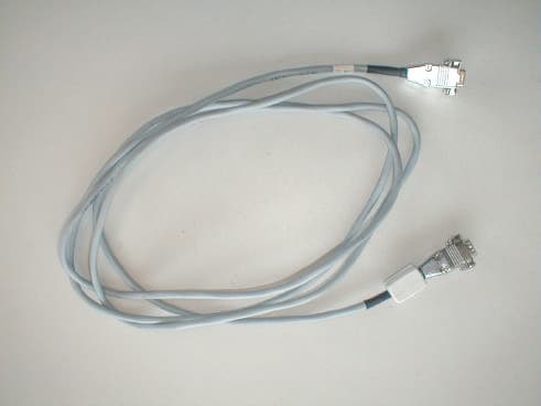
Click to zoom
Application Details
- Equipment Class
- DXX - Part 15 Low Power Communication Device Transmitter
- Date of Grant
- Jun 23, 2003
- Application Purpose
- Original Equipment
- Date of Application
- Jun 22, 2003
- Equipment Note
- Tag Reader
- Frequency Range
- 13.56000000 - 13.56000000
- Company
- ASK
- Country
- France
Documents & Files
Document Text
Text extracted from the exhibit documents filed with the FCC. Open a document above to read the original.
Users Manual
ASK R&DRéf. : RD-ST-03022-10Rév.: 1.0 1 / 10 ASK 5 traverse des Brucs. Les BouillidesR&D001-Form1 06560 VALBONNE SOPHIA ANTIPOLIS Tel : 04 97 21 40 00 Fax : 04 92 38 93 21 USER MANUALLDB 2 ASK LDB 2 DESKTOP READER ASK R&DRéf. : RD-ST-03022-10Rév.: 1.0 2 / 10 ASK 5 traverse des Brucs. Les BouillidesR&D001-Form1 06560 VALBONNE SOPHIA ANTIPOLIS Tel : 04 97 21 40 00 Fax : 04 92 38 93 21 FCC Compliance Statements This equipment has been tested and found to comply with the radiated limits for a Class B digital device, pursuant to Part 15 of the FCC Rules. These limits are designed to provide a reasonable protection against harmful interferences in a residential installation. This equipment generates, uses and can radiate radio frequency energy and, if not installed and used in accordance with the instructions, may cause harmful interference to radio communications. However, there is no guarantee that interference will not occur in a particular installation. If this equipment does cause harmful interference to radio or television reception, which can be determined by turning the equipment off and on, the user is encouraged to try the correct interference by one or more of the following measures: - Reorient or relocate the receiving antenna. - Increase the separation between the equipment and receiver. - Connect the equipment into an outlet on a circuit different from that to which the receiver is connected. - Consult the dealer or an experienced radio/TV technician for help. This device complies with Part 15 of the FCC rules. Operation is subject to the following two conditions. (1) This device may not cause harmful interferences. And (2) this device must accept any interference received, including interference that may cause undesired operation. The ASK LDB 2 reader was submitted and a grand of authorization received from the FCC as device under the intentional radiator requirements of Part 15, Subpart C. The party that incorporates this device into their product is responsible for verification of the emissions produced by the final product and must adhere to the limits specified in the Code of Federal Regulation 47, Part 15, subpart B. Compliance accessories: The accessories associated with this equipment are: shielded serial cable with ferrite tube and linear sector adaptor (12V DC 500mA). These accessories are required to be used in order to ensure compliance with the FFC rules. Caution: Any changes or modification not approved by ASK could void user’s authority to operate the equipment. Switching power mode adaptors are prohibited. CE Compliance statement The ASK LDB 2 reader is in conformity with European requirements, this product has been assessed to the following standard: EN 300 330 EN 301 489-3 EN 50121-4 EN 60950-1 ASK R&DRéf. : RD-ST-03022-10Rév.: 1.0 3 / 10 ASK 5 traverse des Brucs. Les BouillidesR&D001-Form1 06560 VALBONNE SOPHIA ANTIPOLIS Tel : 04 97 21 40 00 Fax : 04 92 38 93 21 TABLE OF CONTENTS 1SCOPE OF MANUAL4 1.1UNPACKING AND INSPECTION4 2LDB 2 READER4 2.1READER COMPONENTS5 2.1.1Coupler board5 2.1.2Antenna board6 2.1.3Power supply board6 2.1.4Contact card interface board7 2.2Assembly7 3READER SETUP8 3.1INSTALLING A NEW SAM IN READER8 3.2READER CONNEXION9 4HOW TO USE THE READER10 4.1CONTACTLESS OPERATIONS10 4.2CONTACT OPERATIONS10 4.3SOFTWARE10 4.4CLEANING10 USER MANUELLDB 2 DESKTOP READER ASK R&DRéf. : RD-MU-03036-10Rév.: 1.0 4 / 10 Copyright ASK SA - 2003 1 SCOPE OF MANUAL This manual describes ASK LDB 2 reader main features and setup information. This manual is intended for use by end users. No specific tools are required for operation described in this document. 1.1 UNPACKING AND INSPECTION Each LDB 2 kit is shipped with : - serial cable (length : 3 meters) - This user manual - One power supply 110V AC / 12V DC 500mA - LDB 2 reader packaged in plastic case 2 LDB 2 READER LDB 2 readers are contactless readers designed for integrators and operators as development tools as well as desktop readers for card issuing center and point of sales. LDB 2 provides the communication between a terminal and customer smart cards. USER MANUELLDB 2 DESKTOP READER ASK R&DRéf. : RD-MU-03036-10Rév.: 1.0 5 / 10 Copyright ASK SA - 2003 2.1 READER COMPONENTS LDB 2 consists of a control board called ”coupler board”, and antenna board, a DC supply converter board (with two extra SAM sockets) and a contact card interface board. 2.1.1 COUPLER BOARD The coupler board contains a microprocessor, non-volatile memory and a radio frequency transmitting circuitry. This board communicates with smart cards via RF link (provided by an antenna board), and to the terminal via RS-232 interface. The serial rate is set to 115,2 bps. The coupler platforms are GEN320 or GEN325 elements which can be purchased separately at ASK. These two OEM coupler boards are compliant with ISO/IEC14443-2 directives (Radio frequency power and signal interface). Communications can be executed according to the type A or type B of the directive. Figure 1 : GEN 320-GEN 325 board GEN 320 and GEN 325 board are strictly identical, except that on GEN 325, PHILIPS ‘s RC500 chip is added. In this case, the chip just manages MIFARE cryptography mode. The RC500 chip is located (or not) at the bottom of the printed circuit board (PCB). SAM location RS232 connector Antenna connector RC500 chip TOP VIEW BOTTOM VIEW Figure 3 : GEN 320 boardFigure 2 : GEN 325 board USER MANUELLDB 2 DESKTOP READER ASK R&DRéf. : RD-MU-03036-10Rév.: 1.0 6 / 10 Copyright ASK SA - 2003 2.1.2 ANTENNA BOARD The antenna board consists of a printed circuit board with copper traces forming the transmit and the receive antenna. Antenna may be one of several types, varying in dimensions and connection. LDB 2 receives GEN 530 antenna because its area (110x120mm) matches well with a desktop application. This antenna has a tuning capacitor, but no setting is required because it has been optimized in factory. Figure 4 : LDB 2 antenna board : GEN 530 2.1.3 POWER SUPPLY BOARD This b…
Text truncated - open the document above for the full version.
Cover Letter(s)
June 20 th , 2003 CONFIDENTIALITY REQUEST Curtis-Straus LLC 527 Great Road Littleton, MA 01460 USA Re: Confidentiality request for a Low Power Communication Device FCC ID: QYELDB2-RDDE03082 Gentlemen, ASK requests, pursuant to 47CFR 0.459, post grant confidentiality for portions of the material contained in this application. The following document regarding this submission for FCC ID: QYELDB2-RDDE03082 be kept confidential 1. Schematic Diagram of LDB2 (file: Schematic Diagram-LDB2.pdf) 2. Block diagram of LDB2 (file: Block Diagram-LDB2.pdf) 3. Operational description of LDB2 (file: Oper Descr-LDB2.pdf) Specifically, these exhibits contain information relating to circuit function and complexity that could be of benefit to competitors. The material contains trade secrets and confidential information that ASK does not customarily release to the public and which is otherwise not generally available to the public. Regards, François MONTEIL R&D Director ASK Les Bouilles – 15, Traverse des Brucs F-06560 VALBONNE SOPHIA ANTIPOLIS - France
External Photos
FCC ID: QYELDB2-RDDE03082 Page 1/3 1 EXTERNAL PHOTOS OF TESTED EUT 1.1 LDB2 PHOTOS General view, front face (with power adapter and serial cable) General view, front face and rear face. FCC ID: QYELDB2-RDDE03082 Page 2/3 General view, left face and right face. 1.2 Auxiliaries photos (AC/DC adapter) Linear power supply adapter FCC ID: QYELDB2-RDDE03082 Page 3/3 1.3 Auxiliaries photos (RS232 cable)
ID Label/Location Info
FCC ID: QYELDB2-RDDE03082 Page 1/1 1 PRODUCT LABELING 1.1 FCC ID Label This is the copy of the label stuck on the product. Size is 60x30mm. Material is metallic polyester. Printing mode is thermal transfer . 1.2 Location of label on EUT Label is stuck on the under the product (see photo). Lower Face LDB 2 FCC ID : QYELDB2-RDDE03082 Serial : 0314001 made in France This device complies with Part 15 of the FCC rules. Operation is subject to the following two conditions: (1) this device may not cause harmful interferences, and (2) this device must accept any interference received, including interference that may cause undesired operation. Input : 12VDC / 500mA
Internal Photos
FCC ID: QYELDB2-RDDE03082 Page 1/8 1 INTERNAL PHOTOS OF TESTED EUT 1.1 General view of equipment 1.2 General view of assembled boards Assembled boards, upper face. FCC ID: QYELDB2-RDDE03082 Page 2/8 Assembled boards, underside view (antenna). Assembled boards, connector sides Assembled boards, left and right sides FCC ID: QYELDB2-RDDE03082 Page 3/8 1.3 PCB view of GEN 320-GEN325 boards (couplers boards) yuy Detail view (SAM connector removed) SAM Connector RS232 connector Antenna connector FCC ID: QYELDB2-RDDE03082 Page 4/8 1.4 PCB view of GEN 530 board (antenna board) RC500 chip (GEN 325 board) FCC ID: QYELDB2-RDDE03082 Page 5/8 Antenna connector FCC ID: QYELDB2-RDDE03082 Page 6/8 1.5 PCB view of GEN 351 board (DC conversion and SAM extension) Detail view (SAM connectors and EMI cover removed) SAM location FCC ID: QYELDB2-RDDE03082 Page 7/8 1.6 PCB view of GEN 362 board (Contact card interface board) Contact card removed FCC ID: QYELDB2-RDDE03082 Page 8/8 azaz 1.7 Internal photo of linear power supply
Test Report
Actions Mesures ZI des Blanchisseries - 38500 VOIRON - Tél. 04 76 65 76 50 - FAX 04 76 66 18 30 S.A. au capital de 152 449,02 € / R.C. de Grenoble B 329 901 888 / SIRET 329 901 888 00035 / code APE 332 B / n°TVA :FR29 329 901 888 This test report applies only on equipment described hereafter. Proposal number: 200301-2130 Date.........................................:February 6 th ,7 th and 10 th , 2003 Location...................................: SMEE Actions Mesures Laboratory - 38 VOIRON Performed by...........................:Laurent CHAPUS Customer.................................:ASK (Represented by Mr. LOGNON) Les Bouillides – 15, Traverse des Brucs 06560 Valbonne Sophia Antipolis FRANCE Product....................................: LDB2 Type of test..............................: Radiated and Conducted Emission Test Applied standards....................:ANSI C63-4 (1992+2000) 47 CFR Part 15 Subpart C Result of tests........................: Transmitter magnetic field: Comply Transmitter modulation bandwidth: Comply Transmitter radiated emissions from 9kHz to 30MHz: Comply Transmitter radiated emissions from 30MHz to 1GHz : Comply The reproduction of this test report is authorized only under its entire form. This report contents 20 pages. Written by................................:Laurent CHAPUS Date : May 13th, 2003 Signature Approved by............................:Jean-Pierre ORY EMC TEST REPORT Nr 2712-FCC FCCID : QYELDB2-RDE03082 Nr 2712-FCCFebruary 6th ,7th and 10th, 2003page 2 /20 1. System test configuration 1.1. Justification The system was configured for testing in a typical fashion (as a customer would normally use it). The LDB2 was connected to a Personnel Computer. It has been tested with a Personal Computer HP model Vectra Vli8 series. 1.2. HARDWARE IDENTIFICATION: * Equipment Under Test (EUT): LDB 2 Sn : Pre serie • Configuration : The LDB2 is configured with the followings boards : - Coupler board GEN 325 - Antenna board GEN 530 - Power supply board GEN 351 - Contact card interface board GEN 362 • Input/output on LDB2 : - DC power supply 12V/500mA - RS232 serial port • Frequencies : FREQUENCY SOURCEUSE 27,120MHzOscillatorMain clock frequency for RF treatments, FPGA clock 22,1184MHzMicrocontrollerMicrocontroller internal frequency 13,56MHzFPGACarrier frequency and digital filters 9,04MHzFPGASAM main clock source 4,52MHzSAM electrical interface, FPGA SAM clock source 3,6864MHzresonatorMicrocontroller 847,500KHzContactless card sub- carrier, FPGA FPGA internal treatments 423,750KHzFPGAFPGA internal treatments 211,875KHzFPGAFPGA internal treatments 105,937KHzFPGA, RF data rateFPGA internal treatments FCCID : QYELDB2-RDE03082 Nr 2712-FCCFebruary 6th ,7th and 10th, 2003page 3 /20 1.3. Auxiliaries The FCC IDs for all equipment, plus description of all cables used in the tested system are : Trade Mark – Model Number (Serial number) FCC IDDescriptionCable description ASK - LDB2 (sn: Pre-serie) QYELDB2- RDDE03082 Contactless readerDC power unshielded RS232 serial shielded with ferrite tube COMELIT Type AL06E 230Vac/12Vdc-500mA (used for radiated emission test) NonePower supply unit. AC/DC converter with linear transformer. DC Power cable, unshielded, 1.75m. Direct plug-in adapter COMELIT Type AL0512/A 120Vac/12Vdc-500mA (used for conducted emission test) NonePower supply unit. AC/DC converter with linear transformer. DC Power cable, unshielded, 1.75m. Direct plug-in adapter HEWLETT PACKARD Vectra VLI8 PIII-500 P/N: D7963A (sn: FR72565009) DOCPersonnel computerAll data cables are shielded. Power cable unshielded. HEWLETT PACKARD P/N: D2846 (sn JP74001000) DOC21" color monitorShielded video cable with ferrites at each end. Power cable unshielded. HEWLETT PACKARD P/N: C4734-60111 (sn: M971168931) GYUR38SKKeyboardShielded cable Microsoft X04-72167 sn: 9916996-5 DOCMouseShielded cable ASK – C.Ticket ISO 14443-2-3 Mode A and mode B NoneContactless paper ticket - 1.4. Equipment modifications A ferrite is added on the RS232 cable (Ferrite type is Würth Electronik ref. 742 7113) A ferrite is added inside the equipment on DC power wires. (Ferrite type is Würth Electronik ref. 742 700 30) Added ferrite on DC wires 1.5. EUT Exercise software The EUT exercise program used during radiated and conducted testing was designed to exercise the LDB2 in a manner similar to a typical use. Communications mode A and B (contactless reader) of the standard ISO/IEC 14443-2 are tested. FCCID : QYELDB2-RDE03082 Nr 2712-FCCFebruary 6th ,7th and 10th, 2003page 4 /20 Software used for each mode is : Mode A : TESTSCRIPT (running in loop) Mode B : POLLING V1.4 1.6. Special accessories The serial interface cable used for compliance testing is shielded as normally supplied. All these cables are normally recommended to be used with the product. 1.7. I/O cables - 1x DC Power cable : 1.75m (fixed on AC/DC adapter) - 1x shielded serial RS232 cable, SubD9 connectors : 3m. - 2x AC power cords (PC and monitor) : 1.5m - 1x Standard video cable SVGA (with two integrated ferrites) : 1.5m 2. Radiated emission data 2.1. SET-UP The EUT is placed on a non-conducting table of 80cm height. Equipment configuration and running mode: - The LDB2 is connected to the PC with the RS232 serial cable; - The LDB2 is powered by 230V/50Hz with the AC/DC adapter; -PC and EUT are ON; - Software is running; - A contactless paper ticket (mode A or mode B) is placed 1 cm above the reader. The installation of EUT is identical for pre-characterization measurement in a 3 meters full anechoic chamber and for measures on a 10 meters Open site. FCCID : QYELDB2-RDE03082 Nr 2712-FCCFebruary 6th ,7th and 10th, 2003page 5 /20 2.2. TEST EQUIPMENT Test equipment up to 1GHz on 10 meters open site: EquipmentCompanyModelSerialCalibration Due Spectrum AnalyzerHP8568B2732A04140March 22 nd ,2003 Quasi-Peak adapterHP85650A2811A01136March 22 nd ,2003 RF Pre-selectorHP85685A2833A00773March 22 nd ,2003 Biconical AntennaEMCO3104C9401-4636April 4 th ,2003 Log Periodic …
Text truncated - open the document above for the full version.
Test Setup Photos
FCC ID: QYELDB2-RDDE03082 Page 1 / 2 1 CONDUCTED AND RADIATED MEASUREMENT PHOTO 1.1 Conducted emission Front view Rear view Detail view FCC ID: QYELDB2-RDDE03082 Page 2 / 2 1.2 Radiated emission Front View Rear View Detail view
Contact Information
Applicant
Laurent LOGNON(Hardware Engineer)
Test Firm
LCIE Sud-EstJacques Lorquin
Technical Specifications
| # | Rule Parts | Frequency Range | Power Output |
|---|---|---|---|
| 1 | 15C | 13.56 MHz - 13.56 MHz | - |
Other Applications from ASK
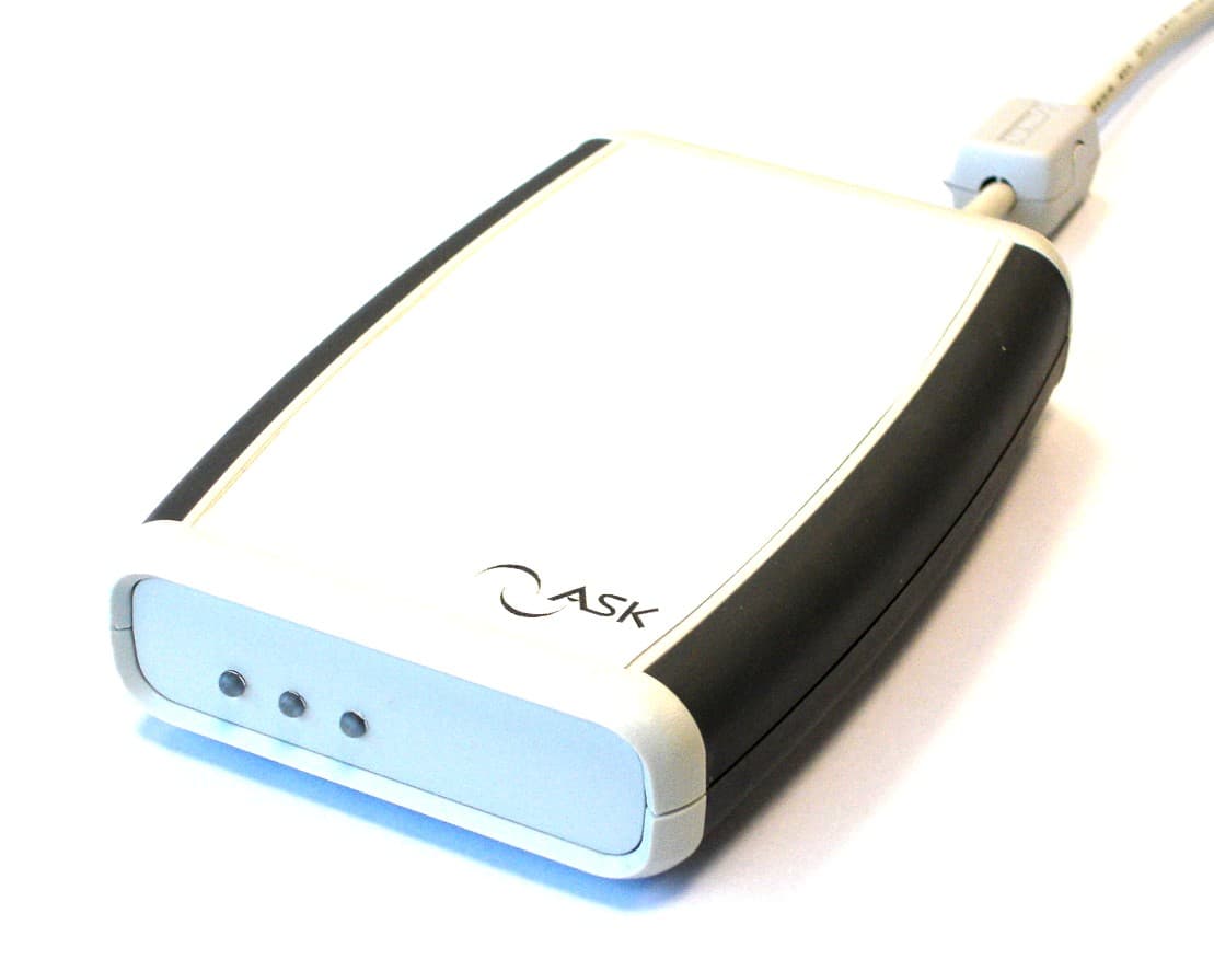
QYERDR41X
Feb 27, 2006USB Card Reader
Equipment Class
DXX - Part 15 Low Power Communication Device Transmitter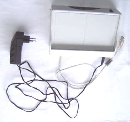
QYELDB3-RDDE05078
Jul 19, 2005Tag Reader
Equipment Class
DXX - Part 15 Low Power Communication Device Transmitter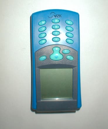
QYEHCRRDDE0207523
Jul 09, 2003Card Reader
Equipment Class
DXX - Part 15 Low Power Communication Device Transmitter