QYM-SMU4Site Monitoring Unit SMU4
Serco Geografix Limited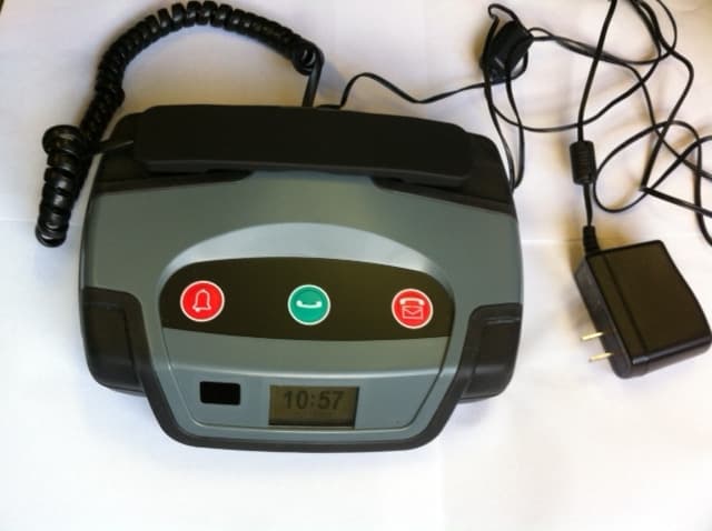
Click to zoom
Application Details
- Equipment Class
- DXX - Part 15 Low Power Communication Device Transmitter
- Date of Grant
- Aug 07, 2014
- Application Purpose
- Original Equipment
- Date of Application
- Aug 07, 2014
- Equipment Note
- Site Monitoring Unit SMU4
- Frequency Range
- 915.15000000 - 915.15000000
- Company
- Serco Geografix Limited
- Country
- United Kingdom
Documents & Files
Document Text
Text extracted from the exhibit documents filed with the FCC. Open a document above to read the original.
External Photos
Serco in Confidence SMU4 EXTERNAL PHOTOS Document Title SMU4 External Photos Serco in Confidence 1 EXTERNAL PHOTOS SMU4 EXTERNAL PHOTO #1 - Top Document Title SMU4 External Photos Serco in Confidence SMU4 EXTERNAL PHOTO #2 - Bottom
ID Label/Location Info
Serco in Confidence ss SMU4 FCC & IC LABEL DETAIL Document Title SMU4 FCC & ID LABEL DETAILS Serco in Confidence 1 SMU4 FCC & IC ID LABEL DETAILS Label Dimensions: 60mm x 40mm Label Material: Aluminium foil label attached with acrylic adhesive. Document Title SMU4 FCC & ID LABEL DETAILS Serco in Confidence
RF Exposure Info
SMU4 EUT RF Exposure:- The SMU4 is intended as a mobile device. A warning statement is included in the user manual advising users to maintain a minimum distance of 20cm. The unit contains three transmitters of which two may transmit simultaneously, one of which has prior approval as an RF module (GSM) FCC ID: QIPBGS3,for installation in mobile devices.The other transmitters are two identical short range 15.249 device transceivers operating at 915.15MHz but they do not operate simultaneously with each other. Evaluation is therefore for exposure potential against the MPE limits given in Appendix A of OET Bulletin 65, 1mW/cm 2 1500-100,000MHz, or F (MHz) / 1500 (for 300-1500MHz) in mW/cm2 Compliance requirements are based upon General population / Uncontrolled exposure. Equation (3) of OET Bulletin 65: where: S = power density (in appropriate units, e.g. mW/cm 2 ) P = power input to the antenna (in appropriate units, e.g. mW) G = power gain of the antenna in the direction of interest relative to an isotropic radiator R = distance to the centre of radiation of the antenna (appropriate units, e.g. cm) Low power transmitter TX1 QP field strength, P = 0.189mW (-7.23dBm). antenna gain is included in the measurement G = 1 Distance, R = 20cm (for mobile use). S = 0.0000376 < 1mW/cm 2 Low power transmitter TX2 QP field strength, P = 0.122mW (-9.13dBm). antenna gain is included in the measurement G = 1 Distance, R = 20cm (for mobile use). S = 0.0000242 < 1mW/cm 2 The SMU4 EUT will be internally fitted with a pre-approved FCC GSM module FCC ID: QIPBGS3 which would therefore be co-located. Maximum powers of this module in the two useable frequency ranges are: 850MHz band: +33.45dBm (2.21309W) 1900MHz band: +30.34dBm (1.08143W) 850MHz band: S = 0.4403MPE limit: 0.5666667 mW/cm 2 1900MHz band: S = 0.2151MPE limit: 1 mW/cm 2 For co-location we can compare the highest powered Short range device (TX1) and one of either the 850MHz or 1900MHz GSM power densities (worst case/tightest limit is 850MHz band) to the limit and sum the percentage of limit to check 100% is not exceeded: 0.0000376 + 0.4403 = 0.4403376 (77.7% limit)< 100%
Test Report
FCC 47CFR part 15C Test Report For Site Monitoring Unit SMU4 Reference Standard: FCC 47CFR part 15C Manufacturer: Serco Geografix Ltd For type of equipment and serial number, refer to section 3 Report Number: 11-7048-4-13 Issue 03 Supersedes report: 11-7048-4-13 Issue 02 Report Produced by: -R.N. Electronics Ltd. 1 Arnolds Court Arnolds Farm Lane Mountnessing Essex CM13 1UT U.K. www.RNelectronics.comTelephone +44 (0) 1277 352219 [email protected] 2013RN ELECTRONICS LIMITEDREPORT NUMBER 11-7048-4-13 ISSUE 03 ALL RIGHTS RESERVED File nameSERCO.7048-4 ISS 03.DOCX The contents of this report, apart from the referenced ANSI C63.4-2003, are beyond the scope of UKAS Testing Laboratory No. 2360 accreditation. QMF21J – 4; 47CFR15.249, RNE ISSUE 01 AUG 2013PAGE 2 OF 52 Copy No. pdf Arnolds Court, Arnolds Farm Lane, Mountnessing, Brentwood Essex, CM13 1UT Certificate of Test 7048-4 The unit noted below has been tested byR.N. Electronics Limitedand, where appropriate, conforms to the relevant subpart of FCC 47CFR Part 15. This is a certificate of test only and should not be confused with an equipment authorisation. Other standards may also apply. Equipment:Site Monitoring Unit Model Number:SMU4 Proposed FCC ID:QYM-SMU4 Unique Serial Number:50039 Manufacturer:Serco Geografix Ltd Hurricane Way Norwich Norfolk NR6 6EW Full measurement results are detailed in Report Number:11-7048-4-13 Issue 03 Test Standards:FCC 47CFR Part 15.249 effective dateOctober 1 st 2012, Class DXX Intentional Radiator DEVIATIONS: Deviations from the standards have been applied; please section 4.1 within this report. This certificate relates only to the unit tested as identified by a unique serial number and in the condition at the time it was tested. It does not relate to any other similar equipment and performance of the product before or after the test cannot be guaranteed. Whilst every effort is made to assure quality of testing, type tests are not exhaustive and although no non-conformances may be found, this doesn't exclude the possibility of unit not meeting the intentions of the standard or the requirements of the Federal Regulations, particularly under different conditions to those during testing. Any compliance statements are made reliant on (a) the application of the product and use of the assigned band being acceptable to the FCC and (b) the modes of operation as instructed to us by the Customer based on their specific knowledge of the application and functionality of the EUT. Statements of compliance, where measurements were made, do not include the measurement uncertainty. The measurement uncertainty, where stated, is the expanded uncertainty based on a standard uncertainty multiplied by a coverage factor of k=2, providing a level of confidence of approximately 95%. Date of Test:8th August 2013-29th November 2013 Test Engineer: Approved By: Managing Director Customer Representative: 2013RN ELECTRONICS LIMITEDREPORT NUMBER 11-7048-4-13 ISSUE 03 ALL RIGHTS RESERVED File nameSERCO.7048-4 ISS 03.DOCX The contents of this report, apart from the referenced ANSI C63.4-2003, are beyond the scope of UKAS Testing Laboratory No. 2360 accreditation. QMF21J – 4; 47CFR15.249, RNE ISSUE 01 AUG 2013PAGE 3 OF 52 1 Contents 1Contents............................................................................................................... 3 2Equipment Under Test (EUT) ............................................................................... 4 2.1Equipment Specification ....................................................................................... 4 2.2EUT Configurations for testing.............................................................................. 5 2.3Functional Description.......................................................................................... 5 2.4EUT Modes .......................................................................................................... 5 2.5Emissions Configuration....................................................................................... 6 3Summary of test results ........................................................................................ 7 4Specifications....................................................................................................... 8 4.1Deviations ............................................................................................................ 8 4.2Tests at Extremes of Temperature & Voltage........................................................ 8 4.3Measurement Uncertainties.................................................................................. 8 5Tests, Methods and Results ................................................................................. 9 5.1AC power line conducted emissions ..................................................................... 9 5.2Intentional radiator field strength......................................................................... 11 5.3Radiated emissions ............................................................................................ 13 5.4Frequency stability ............................................................................................. 16 5.5Occupied bandwidth ........................................................................................... 17 5.6Band Edge ......................................................................................................... 18 5.7Duty cycle .......................................................................................................... 19 6Plots and Results ............................................................................................... 20 6.1AC power line conducted emissions plots ........................................................... 20 6.2Intentional radiator field strength plots ................................................................ 22 6.3Radiated emissions plots.................................................…
Text truncated - open the document above for the full version.
Test Setup Photos
1.1 Test set-up, spurious emissions
Contact Information
Applicant
Matthew Armiger(General Manager)
Technical Contact
Test Firm
R.N. Electronics Ltd.Roger Ray
Technical Specifications
| # | Rule Parts | Frequency Range | Power Output |
|---|---|---|---|
| 1 | 15C | 915.15 MHz - 915.15 MHz | - |
Other Applications from Serco Geografix Limited
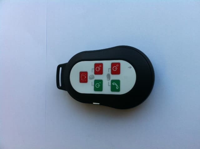
QYM-MID2
May 21, 2014Monitor Interface Device
Equipment Class
DXT - Part 15 Low Power Transceiver, Rx Verified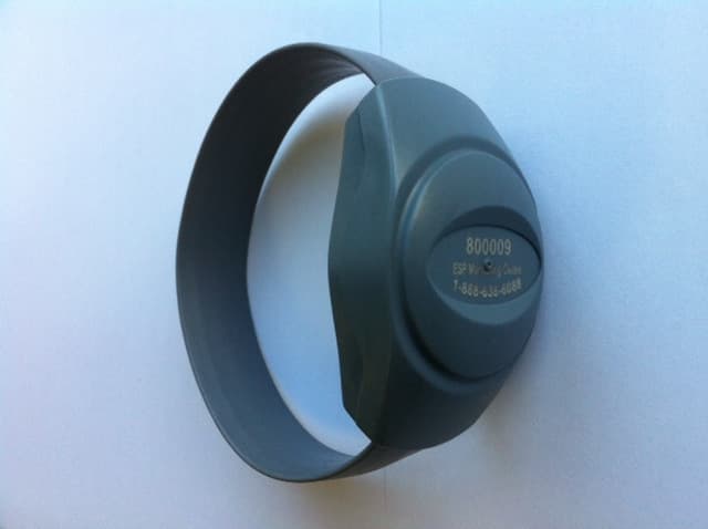
QYM-PID3X
May 06, 2014Personal Identity Device
Equipment Class
DXT - Part 15 Low Power Transceiver, Rx Verified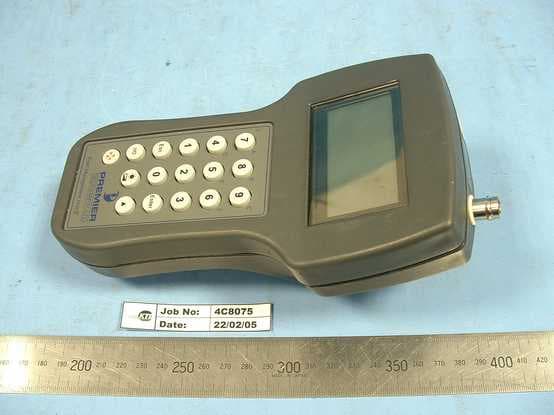
QYMFMU002
Feb 26, 2007Alarm Device
Equipment Class
DSR - Part 15 Remote Control/Security Device Transceiver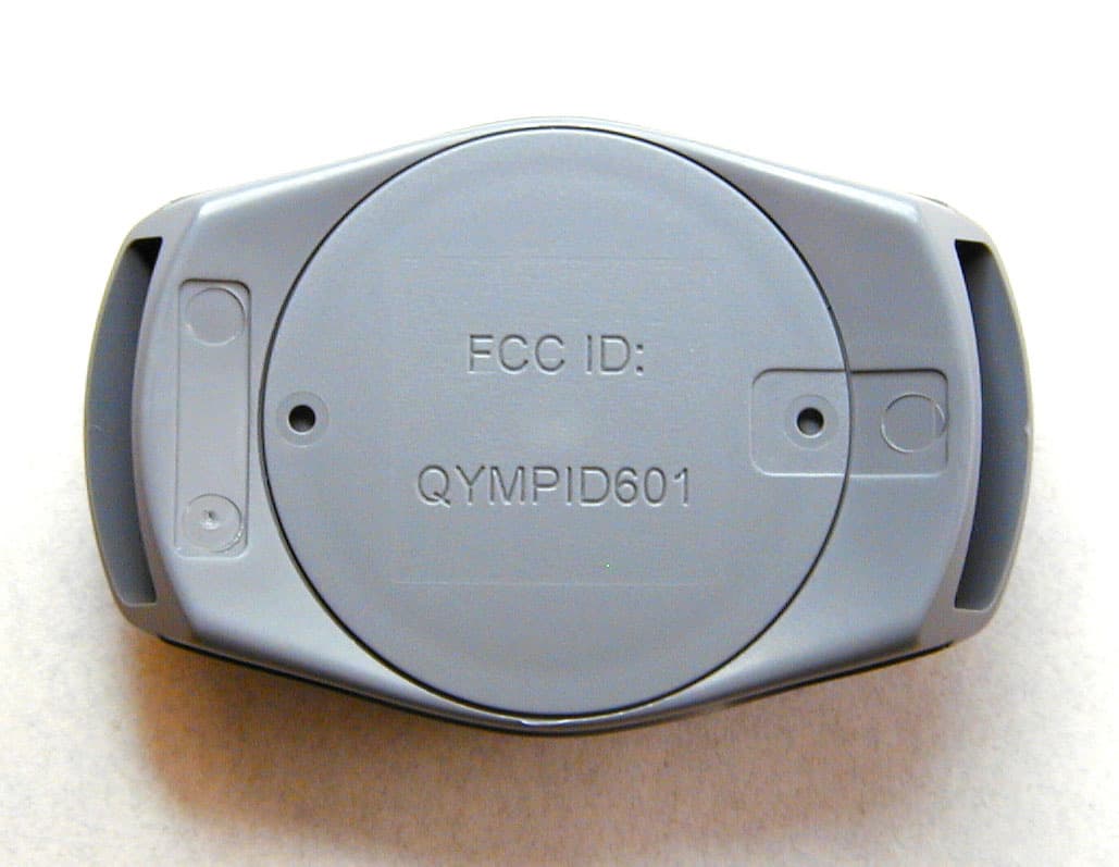
QYMPID601
May 19, 2003Personal Identification Device
Equipment Class
DXX - Part 15 Low Power Communication Device Transmitter