QYMFMU002Alarm Device
Serco Geografix Limited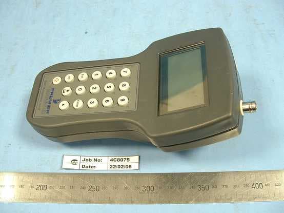
Click to zoom
Application Details
- Equipment Class
- DSR - Part 15 Remote Control/Security Device Transceiver
- Date of Grant
- Feb 26, 2007
- Application Purpose
- Original Equipment
- Date of Application
- Feb 25, 2007
- Equipment Note
- Alarm Device
- Frequency Range
- 433.92000000 - 433.92000000
- Company
- Serco Geografix Limited
- Country
- United Kingdom
Documents & Files
Document Text
Text extracted from the exhibit documents filed with the FCC. Open a document above to read the original.
Users Manual
FIELD MANAGEMENT UNIT 2 (FMU2) USER MANUAL Field management Unit 2 – User manual FMU2 User Manual FMU2-Manual-V1-05USA.doc 6/02/2007 Page 1 of 12 CONTENTS CONTENTS ...........................................................................................................................1 1 INTRODUCTION ............................................................................................................2 1.1 FMU2 Top View.......................................................................................................3 1.2 FMU2 Bottom View .................................................................................................3 1.3 FMU2 End View.......................................................................................................3 1.4 FMU2 Keypad..........................................................................................................4 2 MENUS ...........................................................................................................................5 2.1 Password Menu.......................................................................................................5 2.2 Main Menu...............................................................................................................5 2.3 Monitor Menu...........................................................................................................5 2.4 PID Menu.................................................................................................................5 2.5 SMU Menu...............................................................................................................6 2.6 SMU Sub Menus .....................................................................................................6 2.6.1 SMU Control Menu...........................................................................................6 2.6.2 SMU Phone Menu............................................................................................6 2.6.3 SMU Status Menu ............................................................................................6 2.6.4 SMU Calibration Menu .....................................................................................7 2.6.5 SMU Setup Menu.............................................................................................7 2.7 Tracker Menu ..........................................................................................................8 2.8 Repeater Menu........................................................................................................9 2.9 System Menu.........................................................................................................10 3 MISCELLANEOUS .......................................................................................................11 3.1 Internal Battery Charging. .....................................................................................11 3.2 Wand .....................................................................................................................11 3.3 Uploading Monitor Data to a PC ...........................................................................11 3.4 External Radio Antenna ........................................................................................11 3.5 Reset Switch..........................................................................................................11 3.6 MOT Function........................................................................................................11 FMU2 User Manual FMU2-Manual-V1-05USA.doc 6/02/2007 Page 2 of 12 1 INTRODUCTION Field Monitoring Units 2 (FMU2’s) have an operating frequency of 433.92 MHz.There are two encryption methods for the FMU2 firmware, one for Premier Geografix Ltd (PGL) Personal Identity Devices (PIDs) and Site Monitoring Units (SMUs) and the other for iSecuretrac PIDs and SMUs. The firmware version number provides the differentiation. • PGL version numbers are 1.nn • iSecuretrac version numbers are 2.nn. (See Section 2.9 for an explanation). There are firmware variants for the United Kingdom, Italy, Australia (other than Wooraloo), Wooraloo and Austria. The Italian variant can be in English or Italian. (See Section 2.9 for an explanation). The FMU2’s are configured either for use by Field Monitoring Officers (FMOs) or for test Engineers. (See Section 2.9 for an explanation). PGL Personal Tracking Devices (PTDs) and Repeaters can only be configured using a FMU2, not by a Psion Workabout FMU. PREMIER GEOGRAFIX 1. Monitor menu 2. PID menu 3. SMU menu 4. Tracker menu 5. Repeater menu 6. System menu 1. Monitor all PIDs 2. Set nominated PID 3. Record all PIDs 4. Record one PID 5. Clear PID records 6. Upload recorded data 1. Get Status 2. Clear Tamper 3. Change Mode 4. Get Age 5. Activate PID 6. Deactivate PID 1. Control Menu 2. Phone Menu 3. Status Menu 4. Calibration Menu 5. Setup Menu 1. Get Status 2. Clear Events 3. Change Mode 4. Set phone numbers 5. Power down phone 6. Set PID ID 1. Get Status 2. Change Mode 3. Monitor repeater 1. Display system data 2. Set FMU time 3. Set FMU date 4. Sync FMU to CCS time 1. Power down SMU 2. Call CCS for update 3. Restart SMU from CCS 4. Reset event queue 5. Force callback 1. Set CCS phone no. 2. Set Voice phone no. 3. Set line type 1. Get SMU status 2. Get PID status 3. Get SMU time 1. Cal radio 2. GSM Signal On/Off 3. Add PID to SMU 4. Delete one PID 5. Delete all PIDs 1. Clock/display/alarm 2. Set SMU time Figure 1 FMU2 Field Monitoring Officer’s Menu Structure FMU2 User Manual FMU2-Manual-V1-05USA.doc 6/02/2007 Page 3 of 12 1.1 FMU2 Top View 1.2 FMU2 Bottom View 1.3 FMU2 End View FCC Compliance WARNING: Changes or modifications to the transmitter not expressly approved by the manufacturer could void the user's authority to operate this RF device. This device complies with part 15 of the FCC Rules. Operation is subject to the following two conditions: (1) This device m…
Text truncated - open the document above for the full version.
Block Diagram
Keypad Display DC Power Regulation Battery Charging Real Time Clock Static RAM CPU UART Watchdog UHF TXUHF RX Infra-Red Port 418 MHz or 433 MHz 418 MHz or 433 MHz Loop Antennas IR Window External IR Wand BNC Female 5.0V 6.0V 9.0V DC RS232 Level RS232 External BLOCK Diagram of FMU2.
Block Diagram
IN RX2 Module H8 UART TX Module Loop Antenna FMU2 RF Block Design
Cover Letter(s)
Yunus Faziloglu/USA/VERITAS 02/26/2007 02:32 PM To Kathlene McQuaid/USA/VERITAS cc bcc Subject CS02432 Serco Geografix FCC ID: QYMFMU002 "Response to TCB.PDF" ---- Forwarded by Yunus Faziloglu/USA/VERITAS on 02/26/2007 02:28 PM ----- "Michael Gaukroger " <[email protected]> 02/26/2007 11:11 AM To Yunus Faziloglu/USA/VERITAS@VERITAS cc Subject RE: FW: CS02432 Serco Geografix FCC ID: QYMFMU002 TCB Questions Hi Yunus, Please find enclosed the FCC label with ID as requested plus photos of where the label is to be placed. Regards Mike -----Original Message----- From: [email protected] [mailto:[email protected]] Sent: 23 February 2007 22:38 To: Michael Gaukroger Subject: RE: FW: CS02432 Serco Geografix FCC ID: QYMFMU002 TCB Questions Hi Mike, The label issue is still open. Please supply the FCC label, that shows the FCC ID and photo of where it is placed on the device. Drawings are acceptable. The latest label document we have has IC number on it, which is for Canada. The other issues are OK. Best Regards, Yunus Faziloglu Curtis-Straus LLC Bureau Veritas "Michael Gaukroger " <[email protected]> 02/23/2007 07:01 AM To Yunus Faziloglu/USA/VERITAS@VERITAS cc Subject RE: FW: CS02432 Serco Geografix FCC ID: QYMFMU002 TCB Questions Hi Yunus, Please find attached the new Operational description as requested including the information needed and a photo with arrow highlighting the antenna. Please let me know if we can proceed with the certificate. Regards Mike -----Original Message----- From: [email protected] [mailto:[email protected]] Sent: 22 February 2007 19:42 To: Michael Gaukroger Subject: RE: FW: CS02432 Serco Geografix FCC ID: QYMFMU002 TCB Questions Hi Mike, We are only concerned about the signals transmitted from the device. As part of its receive function it can do anything and that is fine. As part of its transmit function, if it only sends an alarm activation signal to the FMU when the alarm button is pressed, then it is an allowed control signal under 15.231(a). Operational description must be very clear on the purpose of the device and the types of signals it sends. I think at this point an exhibit from the applicant describing how it meets the operational limitations of 15.231(a) item by item, will be the best approach. Please advise your client. And regarding the BNC antenna issue, it is OK that is for the receive antenna. Please show the location of the transmit antenna on a photo. Best Regards, Yunus Faziloglu Curtis-Straus LLC Bureau Veritas "Michael Gaukroger " <[email protected]> 02/22/2007 05:36 AM To Yunus Faziloglu/USA/VERITAS@VERITAS cc Subject RE: FW: CS02432 Serco Geografix FCC ID: QYMFMU002 TCB Questions Hi Yunus, The FMU2 is a tracker that is part of a human alarm tagging system. The FMU2 receives signals from transmitters (personal identification devices) on human body parts. It also has the ability to transmit as part of control signal as an example if the user is being attacked he/she can press the panic alarm button that sends the special message to the SMU which forces the SMU to make a call back to the base which is received as a distress signal. Please advise Regards Mike -----Original Message----- From: [email protected] [mailto:[email protected]] Sent: 21 February 2007 22:43 To: Michael Gaukroger Subject: RE: FW: CS02432 Serco Geografix FCC ID: QYMFMU002 TCB Questions Hi Mike, 1. I am afraid not. The device's whole purpose must be to control a process or trigger an action in response to an event. Operational description states that it is intended for status monitoring and settings changing of SMU's and PID's. It may have the ability to activate and alarm at times, but that doesn't seem to be all it does or its main purpose. 2. i. ok ii. ok iii. The antenna connector type BNC is considered standard and any other antenna with a BNC connector can be substituted easily. This does not satisfy the antenna requirement of 14.203. 3. ok 4. ok 5. The label supplied does not show the FCC ID. 9. ok Best Regards, Yunus Faziloglu Curtis-Straus LLC Bureau Veritas "Michael Gaukroger " <[email protected]> 02/21/2007 11:37 AM To Yunus Faziloglu/USA/VERITAS@VERITAS cc Subject RE: FW: CS02432 Serco Geografix FCC ID: QYMFMU002 TCB Questions Hi Yunus, 1. I have spoken to the manufacturer and the FMU2 has the ability to send a special message to the SMU which then dials out that there is a problem. So the FMU2 does control the SMU. Does this clear up the issue? 2, 3, 4 and 5 please find attached. 9 my client does not request confidentiality. Regards Mike -----Original Message----- From: [email protected] [mailto:[email protected]] Sent: 21 February 2007 14:39 To: Michael Gaukroger Subject: RE: FW: CS02432 Serco Geografix FCC ID: QYMFMU002 TCB Questions Hi Mike, Regarding the responses, 1. From the description of what the device does, it appears it is not intended for control of any end device as explained in 15.231(a). Meaning if SMU's are not controlling anything, then they are not control devices and the signals sent by the FMU's can not be considered as control signals. It needs to control something like an alarm or switch in the end. This device can not operate under paragraph (a), instead paragraph(e) is available, but it will require new test data to demonstrate compliance. 2. The descriptions provided must be in the operational description document. 3. Still open. 4. Still open. 5. The label shown in the photos does not have FCC ID on it. Please supply a label exhibit with all the label related information and photo or drawing. 6. OK 7. OK 8. OK. 9. Still open. 10. Section C4 of the report should include the justification you provided in your response. 11, 12 and 13 - A new report demonstrating compliance to 15.231(e) is needed as explained above. Best Regards, Yunus Faziloglu Curtis-Straus LLC Bureau Veritas "Michael Gaukroger " <[email protected]> 02/14/2007 11:32 AM To Yunus Faziloglu/…
Text truncated - open the document above for the full version.
ID Label/Location Info
Artwork Approval Artwork prepared for: SERCO GEOGRAFIX LTDCreated by: Alan Nye CILS product code: 44B-8894Scale: 1:1 Plate colour separation: COMPRevisions: Computer Imprintable Label Systems Limited 2 Southdownview Way Broadwater Business Park Worthing West Sussex BN14 8NL United Kingdom TEL + 44 (0) 1903 219000 FAX + 44 (0) 1903 219111 EMAILinfo @ cils-international.com HTTP: // www.cils-international.com 08-696-00-BC PLEASE NOTE: Label outline will not be printed CILS APPROVALCUSTOMER APPROVAL Sales: Date: Manufacturing: Date: Signature: Date: Customer Order No : Customer Label Ref : Quantity : Base Substrate : Adhesive Type : Printguard Substrate : Label Height : Label Width : Vertical Repeat : Horizontal Repeat : Vertical Header Gap : Horizontal X inset : Labels Down Sheet : Labels Across Sheet : Labels Per sheet : Radius Corners : Sheet Size : Over-printing Detail : 07/020028 29.9 mm Special Shape 100 8100M Matt White Polyester Pemanent Solvent Acrylic 1200/125 Polycarbonate Overlaminate 29.90 mm 29.90 mm 33.00 mm N/A N/A 5.00 mm N/A 1 N/A TBA N/A N/A FORMAT APPROVAL FCC ID: QYMFMU002 SGL FMU 2
Internal Photos
Please find the location of the transmit antenna on the photo
Operational Description
Intended application for the device The FMU is a handheld device used to change the settings (via Infrared communication) and monitor the status of Site Monitoring Units (SMUs), Personal Identification Devices (PIDs) and other SGL produced equipments. FMU also has a panic button to be used if the officer encounters difficulties. Pressing the button will trigger an immediate transmission to any SMU in range. The SMU will flash the display backlight to acknowledge reception of the message to the officer and report the panic message to the control centre. ii. Modulation type, different transmit modes/packets and their corresponding ON-OFF times The modulation scheme used in FMU2 is 2-FSK. FMU2 uses only one mode of transmission. FMU2 will transmit it status every 2 minutes + 15 seconds (random element) for an hour. Also if the panic button is enabled it will transmit a message for the next five second. Transmission Message structure: The transmitted message structure is shown below: Message byte function Bytes 7 – 8 are used to synchronize the receiving UART, i.e. to determine the start of the individual bytes in the actual message. Byte 9 is always 0x55 for FMU message, i.e. this byte distinguishes regular FMU messages from any other message in the system. Bytes 12 – 17 inclusive are encrypted. Bytes 10 – 11 hold pseudo random code used to access the accelerator table when decrypting the message. Bytes 12 – 15 inclusive hold the FMU identification number. Byte 16 holds the number of times the pseudo code table ‘rolls over’. Byte 17 holds the FMU status. Bytes 18 – 19 hold the cyclic redundancy check for bytes 10 – 17 inclusive. The received FMU message structure is assumed to be as shown below: 0 1 2 3 4 5 6 7 8 9 10 55 PRH PRL ID3 ID2 ID1 ID0Seq No StatCRC L CRC H Panic Message: The main purpose of the panic button is to inform the central sever that the Field monitoring officer have encounters some problem. Once the Site monitoring unit receives this message it will immediately contact the central server via PSTN or GSM network. Status Byte of FMU: D7 D6 D5 D4 D3 D2 D1 D0 P X X X X X X X P=1 Panic message X = Not used P=0 FMU message 0 1 2 3 4 5 6 7 8 9 10 11 12 13 14 15 16 17 18 19 AA AA AA AA AA AA AA FF FF 55 PRHPRLID3ID2ID1 ID0 Seq No StatCRC L CRC H If a panic button is pressed the first bit of the status byte will set to high. On reception any such messages the SMU (Site monitoring Unit) will immediately dial out either through PSTN or GSM network. FMU will also transmit the same message for 5 seconds, when a panic button is pressed. FMU message: When the FMU is switched on initially, it will also transmit its status (same message but the first bit of the status byte will be low) every 120 + 15 sec (random element) for an hour to check the integrity of the transmission. On reception the SMU will log the details of FMU2 for later analysis. FCC Section 15.231: a) As explained before FMU2 transmits its status (message) along with a control signal. (First bit of the status byte, which control signal -whether to send panic message or not) 1. Panic message is a manually operated switch, which automatically deactivates the transmitter with in not more than 5 seconds of being released. 2. The transmitter will automatically cease transmission within 5 seconds after the activation. FMU firmware will automatically deactivate the transmitter after 5 seconds for panic. 3. FMU2 will send its own status to check the integrity of the transmission. (The total duration of transmission is not exceeding 2 seconds an hour). Also, this is not a periodic transmission. 4. FMU2, is when activated to signal the panic, will operate during the pendency of alarm condition. 5. Not applicable. iii. Antenna type and its connector. Please note the antenna connector can not be a standard type connector for a hand-held unlicensed device. Reception antenna is a whip connected via a BNC, whilst transmission is via copper strips on the PCB and hence no connector.
Parts List/Tune Up Info
BILL OF MATERIALS FOR FMU2 GENERAL ASSY V104-433 ISSUE 1 Qty Reqd Per Product DescriptionValue / Man Part Manufacturer:Supplier FMU2 GENERAL Number 1ANTENNA (FMU) BNC STRAIGHTBNCUHFF-433MHz 1ANTENNA CABLE, FMU2FMU2ANTCAB01 ISSUE1 1BATTERY PACK 6.0V 1.0AH 5xAAAL CELLSFMU2BATT01 ISSUE1/ STEATITESTEATITE BG03P3MD19 1BATTERY PAD (RETENTION) (FMU2BATTPAD01)FMU2BATTPAD01 BDKBDK ISSUE1 1BATTERY RETENTION STRAP (FMU2BATTRET01)FMU2BATTRET01 WALKER RUBBER & WALKER RUBBER & ISSUE1PLASTICSPLASTICS 1CONNECTOR BNC ISOLATED PANEL MOUNT JACK VBI1094AVITELECECLIPSE 50ohm 1CONNECTOR, TRIAXDG102A014WWFISCHERWWFISCHER 1DISPLAY MOUNTING SET FMU227010680-00PHOENIX MECANOPHOENIX MECANO 1ENCLOSURE FMU2 (BELUGA 180 WITH DISPLAY27020200-00PHOENIX MECANOPHOENIX MECANO OPENING MODIFIED TO DRG.NO.FMU2REARCASE & 1FLAT FLEXIBLE CABLE (16 WAY 0.5 PITCH 140MM FFC0.50A16/0140L3.0-3.AXON CABLE LTDAXON CABLE LTD LONG)0-06.0-06.0FBBB 1FLEXIBLE CIRCUIT, FMU2 LCDFMU2FLEX101 ISSUE1LYNCOLECLYNCOLEC 1GRAPHIC LCD MODULE 128X64 DOTSCW30000054/WG12864STEATITESTEATITE B-YGH 25,01,2005Page 1 of 2 Qty Reqd Per Product DescriptionValue / Man Part Manufacturer:Supplier FMU2 GENERAL Number 1HEADER, 1X20WAYLHCY-20S-B-027/034TOBY ELECTRONICSTOBY ELECTRONICS 1INFRARED WINDOW FMU2 (FMU2WINDOW)FMU2WINDOW ISSUE1INSTRUMENT PLASTICS INSTRUMENT LTDPLASTICS LTD 1KEYPAD FMU2 (PGL DRG. NO. FMU2KEYPAD)FMU2KEYPAD ISSUE3RUBBERTECH2000RUBBERTECH2000 1LABEL FRONT FMU2(PGL DRG. NO. FMU2FRONTLABEL)FMU2FRONTLABEL APEMAPEM ISSUE2 1PCB, FMU2 COMMS PCB V104-433 (POPULATED)FMU2COMMS104-433 1PCB, FMU2 CPU PCB V104 (POPULATED)FMU2CPU104 1PCB, FMU2 KEYPAD PCB V103(POPULATED)FMU2KEYPAD103 1POWER CABLE ASSEMBLY FMU2 FMU2PWRCAB01 CIE GROUPCIE GROUP (DRG.NO.FMU2PWRCAB01)ISSUE2 1PSU CONNECTOR ASSEMBLY FMU2 FMU2PSUCONN01 CIE GROUPCIE GROUP (DRG.NO.FMU2PSUCONN01)ISSUE1 10SELF TAPPING SCREW - BD/BATT FIXING3mm DIA. 8mm LNG PHILIPS FINISH WASH 25,01,2005Page 2 of 2
Parts List/Tune Up Info
BILL OF MATERIALS FOR FMU2 CPU V104 ISSUE 3 07/04/05 ComponentQty Reqd Product DescriptionValue / Man Part PackageManufacturer:Supplier ReferencePer FMU2 Number B11AWD, MIN BUZZER,3-16V DC, 85dB EI-242-B2 PIN THRO HOLERS RS172-7627 BT11BATTERY 3V, LITHIUM, TO BE ADVISEDDRAWING NPB M 20mm TAGGEDH SQUAREDH SQUARED 1336, TO BE C2,C3,C7,C8,C10,C11,C12,C15,21CAPACITOR 10% 16V, CER0.1uF,MCH182C1040603ROHMKESTRONICS C21,C22,C25,C27,C31,C34,C36KK ,C37,C39,C41,C43,C44,C45 C4,C92CAPACITOR 10% 25V, CER1uF1206ROHMKESTRONICS C1,C17,C20,C354CAPACITOR 10% 50V, CER10nF0603ROHMKESTRONICS C32,C33,C403CAPACITOR 10% 50V, CER470nF,1206ROHMKESTRONICS C30,C422CAPACITOR 20% 16V TANT ESR=0.247uF7.3X4.3PANASONICRS C16,C18,C19,C46,C24,C286CAPACITOR 20% 16V, TANT10uF, NRC106M16L6.0XW3.2NECFLINT 07 April 2005Page 1 of 9 ComponentQty Reqd Product DescriptionValue / Man Part PackageManufacturer:Supplier ReferencePer FMU2 Number C291CAPACITOR 20% 16V, TANT22uF, NRD226M167.3X4.3NECFLINT C381CAPACITOR 5% 50V, CER100pF,0603ROHMKESTRONICS C5,C6,C13,C144CAPACITOR 5% 50V, CER22pF0603ROHMKESTRONICS C23,C262CAPACITOR 5% 50V, CER1500pF0603ROHMKESTRONICS J31CONNECTOR, 20 WAY SMD 08-6212-020-340-80N/AELCO/AVXELCO/AVX SERIES6212-ZIF RIGHT ANGLE 0 J1, J22CONNECTOR, 25 WAY (1.0MM M40-6202506N/AHARWINHARWIN PITCH,4.3MM STACKING HEIGHT, PL11CONNECTOR, 8 WAY HEADER 0.1'' 640454-88 WAYAMPFEC PITCH (NON FRICTION LOCK) X21CRYSTAL 16MHz 30pF HC49/4HSMX16MHz / 30pF A161GHC49/4HSMXIQDFEC 07 April 2005Page 2 of 9 ComponentQty Reqd Product DescriptionValue / Man Part PackageManufacturer:Supplier ReferencePer FMU2 Number X31CRYSTAL 3.6864MHz 30pF 3.6864MHz/ 30pF HC49/4HSMXIQDFEC HC49/4HSMXA169E X11CRYSTAL 32.768KHz 12.5pF 32.768KHz / 12.5pFMC406/90SMXSEIKOFEC MC406/90SMX D6,D82DIODE, DUAL SHOTTKY, If=1A HSMS-2815SOT143HEWLETT - PACKARDFEC PULSED, MAX Vf=410mV D31DIODE, SHOTTKY, 50VPEAK, 35V RMS,ES1ASMAGENERAL RS 1A, 15nSEC.INSTRUMENT D1,D2,D4,D74DIODE, SHOTTKY,REV VOLTAGE 20V, MBR0520LT1SOD123MOTOROLAFEC 0.5A, [email protected] J41FFC CONNECTOR, 0.5 PITCH 16 WAY 52559-16920.5PITCH 16 WAY MOLEXRS 52559 SERIES -VERTICAL SMTSM F1,F22FUSE, T1A, 125V, L6.1mm X W2.69mm T1A Farnell 664-728SMLITTELFUSEFEC X HT2.69mm PL2,PL32HEADER, 1.25MM PITCH VERTICAL 53398-0490N/AMOLEXFEC SMT 07 April 2005Page 3 of 9 ComponentQty Reqd Product DescriptionValue / Man Part PackageManufacturer:Supplier ReferencePer FMU2 Number IC71I/C SRAM, 128K X 8, 85nS, K6X1008C2D-GF55SOP322 ALTERNATIVE PART, SEE PART IC101IC GATE STX BUFFER WITH 3 STATE NC7SZ125M5XSOT23/5 OUTPUT ALTERNATIVE FOR 774 IC31IC, LINEAR REG, 1.25A LOW DROP MIC2941ABUTO-263-5MICRELFUTURE OUT, IC111IC, LOW POWER WITH SUPERVISORY MAX6303CUA8 UMAXMAXIMMAXIM CIRCUITS WITH ADJ. IC21IC, MICRO CONTROLLER, CPUHD64F3048F16QFP100HITACHIDIALOGUE IC9,IC142IC, OP-AMP, LOWPOWER, 4MHz GBW, LM7301IM5 / SOT23-5PINNATIONAL DIALOGUE RAIL TO RAILLM7301IM5XSEMICONDUCTOR IC11IC, QUAD 2 INPUT AND GATE74ACT08SCSOIC14FAIRCHILDFAIRCHILD IC51IC, REAL TIME CLOCKDS1284QPLCC28DALLASDT 07 April 2005Page 4 of 9 ComponentQty Reqd Product DescriptionValue / Man Part PackageManufacturer:Supplier ReferencePer FMU2 Number IC41IC, SWITCHING REGMAX887HESASOIC8MAXIMMAXIM IC121IC, TRANSCEIVERICL3227IASSOP16INTERSILINTERSIL IC61IC, UARTSCC2692AC1A44PLCC44PHILIPS+- IC81IC, VOLTAGE CONVERTERMAX860IUA8 UMAXMAXIMMAXIM L11INDUCTOR 33uH 0.9A SHIELDED24S330SMNEWPORTNEWPORT IC131MICROPROCESSOR SUPERVISOR ICMCP100T-475I/TTSOT23-3MICROCHIP PCB1PCB, FMU2 CPU PCB V104NOT POPULATEDN/A R461RESISTOR 1% 0.063W18K0603NEOHMECLIPSE 07 April 2005Page 5 of 9 ComponentQty Reqd Product DescriptionValue / Man Part PackageManufacturer:Supplier ReferencePer FMU2 Number R121RESISTOR 1% 0.063W1K0603NEOHMECLIPSE R30,R422RESISTOR 1% 0.063W100K0603NEOHMECLIPSE R5,R13,R15,R16,R17,R19,R28,17RESISTOR 1% 0.063W10K0603NEOHMECLIPSE R29,R32,R33,R34,R35,R39,R47 ,R50,R51,R52 R101RESISTOR 1% 0.063W10R0603NEOHMECLIPSE R6,R9,R18,R22,R23,R24,R27,R9RESISTOR 1% 0.063W100R0603NEOHMECLIPSE 38,R41 R401RESISTOR 1% 0.063W82K0603NEOHMECLIPSE R141RESISTOR 1% 0.063W300R0603 R31RESISTOR 1% 0.063W11K0603NEOHMECLIPSE 07 April 2005Page 6 of 9 ComponentQty Reqd Product DescriptionValue / Man Part PackageManufacturer:Supplier ReferencePer FMU2 Number R37,R492RESISTOR 1% 0.063W6K80603NEOHMECLIPSE R211RESISTOR 1% 0.063W27K0603NEOHMECLIPSE R451RESISTOR 1% 0.063W68K0603NEOHMECLIPSE R311RESISTOR 1% 0.063W39K0603NEOHMECLIPSE R11RESISTOR 1% 0.063W12K0603 R2,R4,R203RESISTOR 1% 0.063W1M0603NEOHMECLIPSE R361RESISTOR 1% 0.063W120K0603NEOHMECLIPSE R431RESISTOR 1% 0.063W56K0603NEOHMECLIPSE 07 April 2005Page 7 of 9 ComponentQty Reqd Product DescriptionValue / Man Part PackageManufacturer:Supplier ReferencePer FMU2 Number R8,R11,R48,R534RESISTOR 1% 0.063W4K70603NEOHMECLIPSE R25,R262RESISTOR 1% 0.063W560R0603NEOHMECLIPSE R441RESISTOR 1% 0.063W13K0603NEOHMECLIPSE R71RESISTOR 5% 2W6R82W THRO HOLEMEGGITT CGSECLIPSE TR1,TR5,TR83TRANSISTOR N-FETBSS138SOT23NATIONAL RS SEMICONDUCTOR TR6,TR7,TR9,TR114TRANSISTOR NPNFMMT493SOT23ZETEXECLIPSE TR2, TR3, TR103TRANSISTOR P-FETBSS84SOT23NATIONAL DIALOGUE SEMICONDUCTOR TR41TRANSISTOR PNPFZT951SOT223ZETEXECLIPSE 07 April 2005Page 8 of 9 ComponentQty Reqd Product DescriptionValue / Man Part PackageManufacturer:Supplier ReferencePer FMU2 Number D91V. REF 1V24 1%ZRA124F01SOT23ZETEXECLIPSE D51V.REF 4V 1%ZRT040GC1SOT223ZETEXFEC 07 April 2005Page 9 of 9
Parts List/Tune Up Info
BILL OF MATERIALS FOR FMU2 KEYPAD V103 ISSUE 3 10/07/04 Component Qty Reqd Per Product DescriptionValue / Man Part PackageManufacturer:Supplier ReferenceFMU2 KEYPADNumber J1, J22CONNECTOR, 25 WAY (1.0MM M40-6002506N/AHARWINHARWIN PITCH,4.3MM STACKING HEIGHT, D2, D3, D4, D54DIODE, SHOTTKY, If=1A PULSED, MAX HSMS-2810SOT23HEWLETT - PACKARD Vf=410mV D11LED BI-COLOURHSMF-C6553.2 X 2.7 mm SMTHEWLETT - PACKARDRS PCB1PCB, FMU2 KEYPAD PCB V102NOT POPULATEDN/A R1, R22RESISTOR 1% 0.063W270R0603NEOHMECLIPSE TR1, TR22TRANSISTOR N-FETBSS138SOT23NATIONAL RS SEMICONDUCTOR 10 July 2004Page 1 of 1
Schematics
5 5 4 4 3 3 2 2 1 1 DD CC BB AA A2 D5 D6 A15 A11 D1 D2 A15 A8 A5 D4 /RTC EN A3 A3 D6 /WR A0 D4 D4 A7 A4 D5 A3 A3 A11 A1 D6 A4 D0 D0 A7 A[0..16] D0 A4 /RAM EN A6 A9 /RD /WR /RTC EN A13 D1 A0 A0 A12D3 A14 /UART EN D3 D2 A9 A12 A10 A2 A0 D3 A1 A5 A2 A13 D5 D6 A16 A16 D4 D5 /RD A1 A14 A5 A6 D3 A10 A8 D2 /WR D0 D1 D1 A2 A1 D2 UART RESET D7 D7 A[0..16] D7 D7 D[0..7] TXD0 TXDB RXDB /RESET D/C PWRDN BSY RTC IRQ D[0..7] RXDA /RD /RD /WR /RAM EN /UART EN TXDA RXD0 DB3 DB6 DB4 DB[0..7] DB1 DB2 DB7 DB5 DB0 PA[0..5] PA1 PA4 PA2 PA5 PA0 PA3 PA5 PA4 PA3 PA2 PA1 PA0 DB7 DB6 DB5 DB4 DB3 DB2 DB1 DB0 UART IRQ SWITCHED_5VSWITCHED_5V VCC VCC VCC VCC VCC SWITCHED_5V VCC VCC VCC VCC VCC SWITCHED_5V SWITCHED_5V VCC VCC VCC VCC VCC SWITCHED_5V VCC CHARGE_CONTROL2 CHARGE_CONTROL1 BATT_TEMP VBATT SUPPLY_VOLTS T1_OUT R1_IN REG SUPPLY_VOLTS RESET BUTTON RESET BUTTON Title SizeDocument NumberRev Date:Sheetof Premier Geografix Ltd. Hurricane Way, Norwich Norfolk, NR6 6EW Premier Geografix Ltd. FMU2_CPU_Ver1045 FMU2 - CPU Schematic 12Thursday, April 07, 2005 Title SizeDocument NumberRev Date:Sheetof Premier Geografix Ltd. Hurricane Way, Norwich Norfolk, NR6 6EW Premier Geografix Ltd. FMU2_CPU_Ver1045 FMU2 - CPU Schematic 12Thursday, April 07, 2005 Title SizeDocument NumberRev Date:Sheetof Premier Geografix Ltd. Hurricane Way, Norwich Norfolk, NR6 6EW Premier Geografix Ltd. FMU2_CPU_Ver1045 FMU2 - CPU Schematic 12Thursday, April 07, 2005 REAL TIME CLOCK KEYPAD PCB CONNECTORS DISPLAY CONNECTOR BATT VOLTS SUPPLY VOLTS COMMS PCB CONNECTOR BATT TEMP (To Sheet 2) (To Sheet 2) VCC GND TXD RXD PWRDN D/C /RESET BSY P6.0 RXD0 P6.1 TXD0 VCC GND Vo (DB0) (DB1) (DB2) (DB3) (DB4) (DB5) (DB6) (DB7) CS1 CS2 RST R/W D/I E PS (LED) 0V -VO (+4.2V) NC NC GND VCC GND /RESB PROGRAMMING CONNECTOR R23100RR23100R FC 1 C1+ 2 GND 3 C1- 4 OUT 5 FV 6 /SHDN 7 VDD 8 IC8 MAX860IUA IC8 MAX860IUA TXDA 33 RXDA 35 RTSA 32 CTSA 8 TXDB 13 RXDB 11 OP1 14 IP1 5 D7 21 D6 25 D5 20 D4 26 D3 19 D2 27 D1 18 D0 28 A3 7 A2 6 A1 4 A0 2 WRN 9 RDN 10 RESET 38 CEN 39 INTRN 24 NC 1 NC 12 NC 23 NC 34 OP2 31 OP3 15 OP4 30 OP5 16 OP7 17 OP6 29 IP2 40 IP3 3 IP4 43 IP5 42 IP6 41 X1 36 X2 37 VSS 22 VCC 44 IC6 SCC2692 IC6 SCC2692 NC 1 A16 2 A14 3 A12 4 A7 5 A6 6 A5 7 A4 8 A3 9 A2 10 A1 11 A0 12 D0 13 D1 14 D2 15 GND 16 D3 17 D4 18 D5 19 D6 20 D7 21 A15 31 A13 28 A11 25 A10 23 A9 26 A8 27 CE2 30 /CE1 22 R/W 29 VDD 32 /OE 24 IC7 CXK581000AM-10LL IC7 CXK581000AM-10LL R35 10K R35 10K R41100RR41100R R28 10K R28 10K OP 1 V- 2 +IN 3 -IN 4 V+ 5 IC9 LM7301 IC9 LM7301 +C19 10u +C19 10u C1 10N C1 10N 1 3 2 TR3 BSS84 TR3 BSS84 +C18 10U +C18 10U 12 13 11 IC1D 74ACT08 IC1D 74ACT08 R19 10K R19 10K TP2TP2 R24100RR24100R + C28 10UF + C28 10UF + C37 0.1 + C37 0.1 R14 300R R14 300R R18100RR18100R R2 1M R2 1M +C16 10U +C16 10U C15 0.1 C15 0.1 R20 1M R20 1M R6100RR6100R R34 10K R34 10K C10 0.1 C10 0.1 TP9TP9 + C24 10UF + C24 10UF C43 0.1 C43 0.1 + 1 - 2 B1 BUZZER EI-242-B B1 BUZZER EI-242-B TP16TP16 R10 10R R10 10R + C33 0.47UF + C33 0.47UF C41 0.1 C41 0.1 R21 27K R21 27K TP5TP5 TP8TP8 D7 19 D4 16 D3 15 GND 14 A0 10 A1 9 A3 7 A5 5 NC 4 D2 13 D0 11 /CE 20 X1 2 /INTA 1 /OE 22 SQW 23 /RCLR 24 D1 12 X2 3 A4 6 A2 8 D5 17 D6 18 GND 21 VBAT 25 INTB 26 /WE 27 VCC 28 IC5 DS1284Q IC5 DS1284Q A0 36 A1 37 A2 38 A3 39 A4 40 A5 41 A6 42 A7 43 A8 45 A9 46 A10 47 A11 48 A12 49 A13 50 A14 51 A15 52 D8 27 D9 28 D10 29 D11 30 D12 31 D13 32 D14 33 D15 34 P4.5 24 P4.6 25 P4.7 26 A16 53 A17 54 A18 55 A19 56 P6.0 58 P6.1 59 P6.2 60 CLK 61 P7.2 80 P7.3 81 AN4 82 AN5 83 AN6 84 DA1 85 /IRQ0 87 /CS3 88 /CS2 89 /CS1 90 CS0 91 TXD0 12 TXD1 13 RXD0 14 RXD1 15 /IRQ4 16 /IRQ5 17 PB0 2 PB1 3 PB2 4 PB3 5 PB4 6 PB5 7 PB6 8 PB7 9 PA0 93 PA1 94 PA2 95 PA3 96 PA4 97 PA5 98 PA6 99 PA7 100 /AS 69 /RD 70 /HWR 71 /LWR 72 /STBY 62 /RES 63 NMI 64 VSS 65 EXTAL 66 XTAL 67 MD0 73 MD1 74 MD2 75 AVCC 76 VREF 77 VSS 22 VCC 1 VCC 35 VCC 68 VPP 10 VSS 11 VSS 44 VSS 57 AVSS 86 VSS 92 P4.0 18 P4.1 19 P4.2 20 P4.3 21 P4.4 23 P7.0 78 P7.1 79 IC2 H8/3048 IC2 H8/3048 R31 39K R31 39K R15 10K R15 10K C26 1500PF C26 1500PF R16 10K R16 10K C7 0.1 C7 0.1 R17 10K R17 10K TP1TP1 +C46 10u +C46 10u R47 10K R47 10K C45 0.1 C45 0.1 R36 120K R36 120K R33 10K R33 10K R9100RR9100R X2 16MHZ X2 16MHZ R5 10K R5 10K R3 11K R3 11K R22 100R R22 100R 1 2 3 4 5 6 7 8 9 10 11 12 13 14 15 16 17 18 19 20 J3 ELCO 08-6212-020 J3 ELCO 08-6212-020 C22 0.1 C22 0.1 2 1 3 4 D5 ZRT040GC1 D5 ZRT040GC1 2 4 D6B HSMS-2815 D6B HSMS-2815 1 3 D6A HSMS-2815 D6A HSMS-2815 C12 0.1 C12 0.1 R42 100K R42 100K 13 D8A HSMS-2815 D8A HSMS-2815 24 D8B HSMS-2815 D8B HSMS-2815 TP12TP12 BT1 BATTERY BT1 BATTERY 1 2 3 4 5 6 7 8 9 10 11 12 13 14 15 16 J4 FCC 52559-169…
Text truncated - open the document above for the full version.
Contact Information
Applicant
Matthew Armiger(General Manager)
Test Firm
Element Materials Technology Warwick LtdKeith Wright
Technical Specifications
| # | Rule Parts | Frequency Range | Power Output |
|---|---|---|---|
| 1 | 15.231 | 433.92 MHz - 433.92 MHz | - |
Other Applications from Serco Geografix Limited
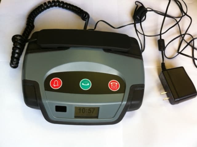
QYM-SMU4
Aug 07, 2014Site Monitoring Unit SMU4
Equipment Class
DXX - Part 15 Low Power Communication Device Transmitter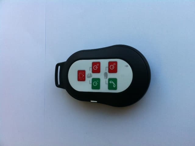
QYM-MID2
May 21, 2014Monitor Interface Device
Equipment Class
DXT - Part 15 Low Power Transceiver, Rx Verified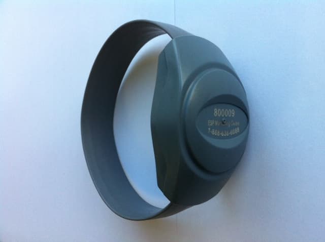
QYM-PID3X
May 06, 2014Personal Identity Device
Equipment Class
DXT - Part 15 Low Power Transceiver, Rx Verified
QYMPID601
May 19, 2003Personal Identification Device
Equipment Class
DXX - Part 15 Low Power Communication Device Transmitter