QZFCT7600Personal Computer
DAEWOO Lucoms Co., Ltd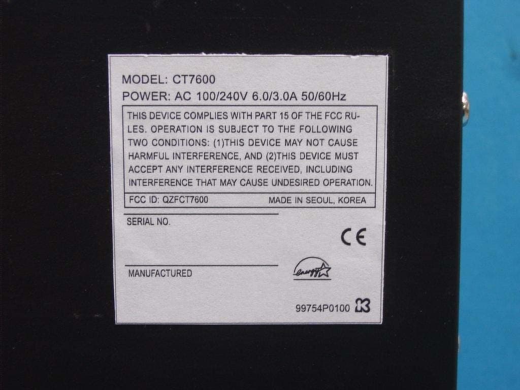
Click to zoom
Application Details
- Equipment Class
- JBC - Part 15 Class B Computing Device/Personal Computer
- Date of Grant
- Apr 06, 2006
- Application Purpose
- Original Equipment
- Date of Application
- Apr 06, 2006
- Equipment Note
- Personal Computer
- Company
- DAEWOO Lucoms Co., Ltd
- Country
- South Korea
Documents & Files
Document Text
Text extracted from the exhibit documents filed with the FCC. Open a document above to read the original.
Users Manual
User’s Manual CT7600 Daewoo Lucoms FCC-B Radio Frequency Interference Statement This equipment has been tested and found to comply with the limits for a ClassBdigital device, pursuant to Part 15 of the FCC Rules. These limits are designed to provide reasonable protection against harmful interference in a residential installation. This equipment generates, uses and can radiate radio frequency energy and,ifnot installed and used in accordance with the instructions, may cause harmfulinterference to radio communications. However, there is no guarantee that interferencewillnot occur in a particular installation. If this equipment does cause harmful interference to radio or television reception which can be determined by turning the equipment off and on, the user is encouragedtotryto correct the interference by one or more of the following measures. - Reorient or relocate the receiving antenna. - Increase the separation between the equipment and receiver. - Connect the equipment into an outlet on a circuit different from that to which the receiver is connected. - Consult the dealer or an experienced radio, TV technical for help. - Only shielded interface cable should be used. Finally, any changes or modifications to the equipment by the user not expressly approved by the grantee or manufacturer could void the users authority to operate such equipment Introduction Thank you for choosing the PM8M3-V (MS-7211 v1.x) Micro-ATX mainboard. The PM8M3-V is design based on VIA® P4M800 & VIA® VT8237R Plus chipsets for optimal system efficiency. Designedfor the Intel® P4 processors supporting Hyper-Threading Technology in the LGA775 package, the PM8M3-V delivers a high performance and professional desktop platform solution. Specifications CPU . Supports Intel® Pentium® 4/ Prescott (LGA 775) processor. . FSB @ 800/533MHz. . Supports Intel P4 Prescott CPU up to 3.2GHz, and Intel P4 Prescott CeleronCPU. Chipset . VIA® P4M800CE chipset - P4 processors FSB (800MHz). - DDR SDRAM memory (333/400MHz). -AGP8x. - Supports 8X V-Link. .VIA®VT8237Rpluschipset - Integrated Hardware Sound Blaster/Direct Sound AC97 audio - Ultra DMA 66/100/133 master mode PCI EIDE controller - ACPI & PC2001 compliant enhanced power management - Supports USB2.0 up to 8 ports Main Memory .Supportstwomemorybanksusingtwo184-pinDDRDIMM. . Supports up to 2GB PC3200 (DDR400) SDRAMs. .Supports2.5vDDRSDRAM. Slots . One AGP (Accelerated Graphics Port) 8x slot. . Two PCI 2.2 32-bit PCI bus slots (support 3.3v/5v PCI bus interface). On-Board IDE . An IDE controller on the VIAR VT8237R plus Chipset provides IDE . HDD/CD-ROM with PIO, Bus Master and Ultra DMA 33/66/100/133 operation modes. . Can connect up to four IDE devices. Audio . AC97 link controller integrated in VT8237R plus. . Realtek® ALC655 6-channel software audio codec. - Compliance with AC’97 v2.2 spec. LAN . Realtek® 8100C / 8110SB (optional). - Supports 10Mb/s, 100Mb/s and 1000Mbs(1000Mbs for 8110SB only). - Compliance with PCI 2.2. - Supports ACPI Power Management. On-Board Peripherals . On-Board Peripherals include: - 1 floppy port supports 2 FDDs with 360K, 720K, 1.2M, 1.44M and 2.88Mbytes -1serialport(COM1) - 1 parallel port supports SPP/EPP/ECP mode - 8 USB 2.0 ports (Rear * 4/ Front * 4) - 1 audio (Line-In/Line-Out/Mic) port - 1 RJ45 LAN jack -1VGAport - 1 COM2 pin header -2SATA150 BIOS . The mainboard BIOS provides “Plug & Play” BIOS which detects the peripheral devices and expansion cards of the board automatically. . The mainboard provides a Desktop Management Interface (DMI) function which records your mainboard specifications. Dimension . Micro-ATX Form Factor: 245mm x 210mm Mounting .6mountingholes. Rear Panel The rear panel provides the following connectors: Hardware Setup This chapter tells you how to install the CPU, memory modules, and expansion cards,aswellashowtosetupthejumpers on the mainboard. It also providesthe instructions on connecting the peripheral devices, such as the mouse, keyboard, etc. While doing the installation, be careful in holding the components and follow the installation procedures. Central Processing Unit: CPU The mainboard supports Intel® Pentium 4 processor. The mainboard uses a CPU socket called LGA775. When you are installing the CPU, make sure to installthe cooler to prevent overheating. If you do not have the CPU cooler, contact your dealer to purchase and install them before turning on the computer. Memory Speed/CPU FSB Support Matrix Overheating Overheating will seriously damage the CPU and the system, always make surethe cooling fan can work properly to protect the CPU from overheating. Overclocking This mainboard is designed to supportoverclocking. However, please makesure your components are able to tolerate such abnormal setting, while doing overclocking. Any attempt to operate beyond product specifications is not recommended. We do not guarantee the damages or risks caused by inadequate operation or beyond product specifications. Memory FSB DDR 333DDR 400 533MHzOKOK 800MHzOKOK LGA775 CPU and Cooler Installation When you are installing the CPU, make sure the CPU has a cooler attached on the top to prevent overheating. If you do not have the cooler, contact your dealer to purchase and install them before turning on the computer. Meanwhile, do not forget to apply some silicon heat transfer compound on CPU before installing the cooler for better heat dispersion. Follow the steps below to install the CPU & cooler correctly. Wrong installation will cause the damage to your CPU & mainboard. 1. The CPU has a land side cover on the bottom to protect the CPU contact from damage. Rotate it to make the pin 1 indicator (yellow triangle) in the left-bottom corner. The availability of it depends on the CPU packing. 2. Take out the accompanying CPU Clip (shown in the right) and rotate it for the same direction as the CPU (Pin 1 indicator is in the left-bottom corner). 3.Use2handstoremovethelandsidecover(ifany).Pleasenotenottotouch the pins. 4. Align …
Text truncated - open the document above for the full version.
Cover Letter(s)
March 06, 2006 Compliance Certification Services Certification Division 561F Monterey Road Morgan Hill, CA 95037 To whom it may concern: We, the undersigned, hereby authorize IST Co., Ltd., to act on our behalf in all manners relating to application for equipment authorization, including signing of all documents relating to these matters. Any and all acts carried out by IST Co., Ltd. on our behalf shall have the same effect as acts of our own. We, the undersigned, hereby certify that we are not subject to a denial of federal benefits, that includes FCC benefits, pursuant to Section 5301 of the Anti-Drug Abuse Act of 1988, 21 U.S.C. 853(a). In authorizing IST Co., Ltd. as our agent, we still recognize that we are responsible to: a) comply with the relevant provisions of the certification program; b) make all necessary arrangements for the conduct of the evaluation, including provision for examining documentation and access to all areas, records (including internal audit reports) and personnel for the purposes of evaluation (e.g. testing, inspection, assessment, surveillance, reassessment) and resolution of complaints; c) make claims regarding certification only in respect of the scope for which certification has been granted; d) do not use our product certification in such a manner as to bring the Certification Division into disrepute and not make any statement regarding our product certification which the Certification Division may consider misleading or unauthorized; e) upon suspension or cancellation of certification, discontinue use of all advertising matter that contains any reference thereto and return any certification documents as required by the Certification Division; f) use certification only to indicate the products are certified as being in conformity with specified standards; g) endeavor to ensure that no certificate or report nor any part thereof is used in a misleading manner; h) ensure that any reference to our product certification in communication media such as documents, brochures or advertising, complies with the requirements of the Certification Division; i) keep a record of all complaints made known to the us relating to the product’s compliance with requirements of the relevant standard and to make these records available to the Certification Division when requested; j) take appropriate action with respect to such complaints and any deficiencies found in products or services that affect compliance with the requirements for certification; k) document the actions taken. This authorization is valid until further written notice from the applicant. Sincerely Yours, Byung-Sun Hwang / Senior Engineer DAEWOO Lucoms co.,ltd.
ID Label/Location Info
ID Label Sample & Location Information
Test Report
IST Co., Ltd EMC LABORATORY TEST REPORT NO. : 06-IST-0147 1 of 22 Certification of Compliance CFR 47 Part 15 Subpart B Test Report File No. : 06-IST-0147 Date of Issue : April 04, 2006 FCC ID : QZFCT7600 Model(s) : CT7600 ■ Basic □ Alternate Kind of Product : Personal Computer Applicant : DAEWOO Lucoms Co., Ltd. Address : 1201~4 AceTechnoTower 5 th , 197-22 Guro-Dong, Guro-Gu, Seoul, Korea Manufacturer : DAEWOO Lucoms Co., Ltd. Address : 1201~4 AceTechnoTower 5 th , 197-22 Guro-Dong, Guro-Gu, Seoul, Korea Test Result ■ Positive □ Negative Reviewed By Approved By Comment(s) - Investigations requested : Measurement to the relevant clauses of FCC rules and regulations Part 15 Subpart B – Unintentional Radiators, Class B. - The test report with appendix consists of 22 pages. - The test result only responds to the tested sample. - It is not allowed to copy this report even partly without the allowance of IST EMC Laboratory. - This equipment as for has been shown to be capable of continued compliance with the applicable technical standards as indicated in the measurement report and was tested in accordance with the measurement procedures specified in ANSI C63.4 2003. S.J.Cho / EMC Group Manager J.H.Lee / Chief IST Co., Ltd EMC LABORATORY TEST REPORT NO. : 06-IST-0147 2 of 22 TABLE OF CONTENTS Table of contents 2 Information of test laboratory, Environmental conditions, Power supply system used, Product information 3 Descriptions of test Conducted Emission 4 Radiated Emission 5 Measurement Uncertainty Calculations 6 Equipment Under Test 7 Test Set-Up (Figure) 8 Summary 9 ■ Test Conditions and Data – Emissions ◆ Conducted Emissions 0.15MHz- 30MHz Applicable Test Conditions / Data and Plots 10-12 ◆ Radiated Emissions 30MHz - 18GHz Applicable Test Conditions / Data and Plots 13-18 Appendix A. The Photos of Test Setup 19-20 B. The Photos of Equipment Under Test 21-22 Note: IST Co., Ltd EMC LABORATORY TEST REPORT NO. : 06-IST-0147 3 of 22 INFORMATIONS OF TEST LABORATORY EMC LABORATORY of IST Co., Ltd. (FCC Filing Lab.) San 21-8, Goan-Ri, Baekam-Myun, Yongin-City Kyonggi-Do, 449-860, Korea TEL : +82 31 333 4093 FAX : +82 31 333 4094 ENVIRONMENTAL CONDITIONS Temperature 18.5 °C Humidity 37 % Atmospheric pressure 1014 mbar POWER SUPPLY SYSTEM USED Power supply system(PC) AC 120V, 60Hz (Refer to the product information) PRODUCT INFORMATION CPU: Supports Intel® Pentium® 4/ Prescott (LGA 775) processor Chipset: VIA® P4M800CE chipset Main Memory: Supports two memory banks using two 184-pin DDR DIMM Slots: One AGP (Accelerated Graphics Port) 8x slot Two PCI 2.2 32-bit PCI bus slots (support 3.3v/5v PCI bus interface) Audio: AC97 link controller integrated in VT8237R plus Realtek® ALC655 6-channel software audio codec LAN: Supports 10Mb/s, 100Mb/s and 1000Mbs(1000Mbs for 8110SB only) Dimension: Micro-ATX Form Factor: 245mm x 210mm - EMC suppression device is not used during the test . - Please refer to user’s manual. IST Co., Ltd EMC LABORATORY TEST REPORT NO. : 06-IST-0147 4 of 22 < Concept Drawing > 215 >150 >40 80 Receiver EUT LISN 80 ≥ 80 80 40 ≥ 80 Measuring apparatus Mains Filter Mains Rear side Equipment under test Coaxial cable Artificial mains networ k Screened room Non-metallic support 80 DESCRIPTIONS OF TEST Conducted Emissions: The measurement were performed over the frequency range of 0.15MHz to 30MHz using a 50 Ω /50uH LISN as the input transducer to a Spectrum Analyzer or a Field Intensity Meter. The measurements were made with the detector set for "Peak" amplitude within a bandwidth of 10KHz or for "quasi-peak" & “Average” within a bandwidth of 9KHz. - Procedure of Test The line-conducted facility is located inside a shielded room No.1. A 1m X 1.5m wooden table 80cm height is placed 40cm away from the vertical wall and 1.5m away from the other wall of the shielded room. The R/S 3725/2 and Hyup-Rip KNW-407 LISN are bonded to bottom of the shielded room. The EUT is located on the wooden table with distance more than 80cm from the LISN and powered from the LISN .The peripheral equipment is powered from the other LISN. Power to the LISNs are filtered by a noise cut power line filters. All electrical cables are shielded by braided tinned steel tubing with inner φ 1.2cm. If the EUT is a DC-powered device, power will be derived from the source power supply it normally will be powered from and this supply lines will be connected to the EMCO LISN. All interconnecting cables more than 1m were shortened by non-inductive bundling to a 1m length. Sufficient time for the EUT, support equipment, and test equipment was allowed in order for them to warm up to their normal operating conditions. The RF output of the LISN was connected to the R/S receiver to determine the frequency producing the maximum emission from the EUT. The frequency producing the maximum level was reexamined using Quasi-Peak mode by manual measurement, after scanned by automatic Peak mode for frequency range from 0.15 to 30MHz. The bandwidth of the receiver was set to 10kHz. The EUT, peripheral equipment, and interconnecting cables were arranged and manipulated to maximize each EME emission. < Side View > IST Co., Ltd EMC LABORATORY TEST REPORT NO. : 06-IST-0147 5 of 22 DESCRIPTION OF TEST Radiated Emissions: The measurement was performed over the frequency range of 30MHz to 1GHz using antenna as the input transducer to a Spectrum analyzer or a Field Intensity Meter. The measurement was made with the detector set for "quasi-peak" within a bandwidth of 120KHz. - Procedure of Test Preliminary measurements were made at 3 meter using bi-conical and log-periodic antennas, and spectrum analyzer to determine the frequency producing the max. emission in anechoic chamber. Appropriate precaution was taken to ensure that all emission from the EUT were maximized and investigated. The system configuration, mode of operation, turn-table azimuth and height with respect to the antenna were noted for each frequency found. The spectrum was scanned from 30M…
Text truncated - open the document above for the full version.
Contact Information
Applicant
Byung-Sun Hwang(Chief Engineer)
Test Firm
IST Co., LtdBong Kyoon Bae
Technical Specifications
| # | Rule Parts | Frequency Range | Power Output |
|---|---|---|---|
| 1 | 15B | - | - |
Other Applications from DAEWOO Lucoms Co., Ltd
QZFL2200
Dec 21, 2006LCD Monitor
Equipment Class
JBP - Part 15 Class B Computing Device Peripheral
QZFCML950
Jul 13, 200519" LCD Monitor
Equipment Class
JBP - Part 15 Class B Computing Device Peripheral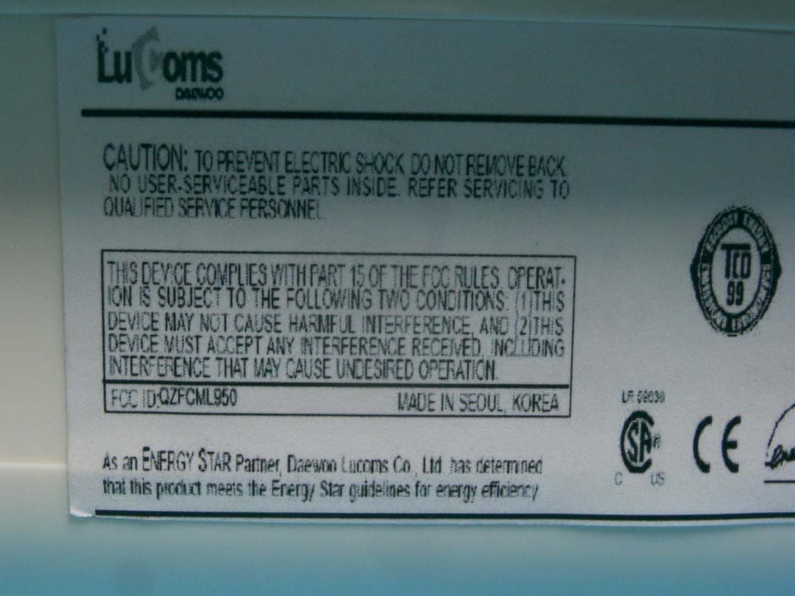
QZFCML750
Jul 13, 200517" LCD Monitor
Equipment Class
JBP - Part 15 Class B Computing Device Peripheral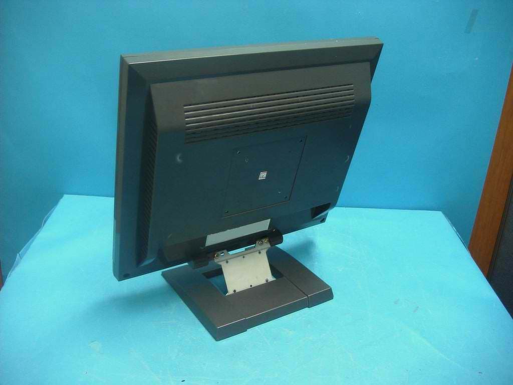
QZFCML710M
Feb 08, 200417 " LCD Monitor
Equipment Class
JBP - Part 15 Class B Computing Device Peripheral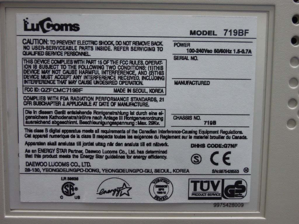
QZFCMC719BF
Sep 03, 200317" Color Monitor
Equipment Class
JBP - Part 15 Class B Computing Device Peripheral