QZG5113RE1 Spread Spectrum Radios
K-Best Technology Inc.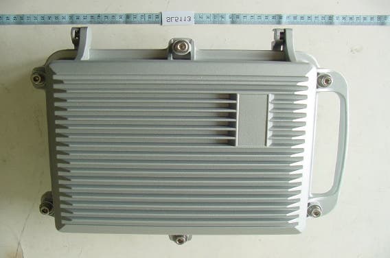
Click to zoom
Application Details
- Equipment Class
- DTS - Digital Transmission System
- Date of Grant
- Mar 23, 2005
- Application Purpose
- Original Equipment
- Date of Application
- Mar 23, 2005
- Equipment Note
- E1 Spread Spectrum Radios
- Frequency Range
- 5822.00000000 - 5838.00000000
- Company
- K-Best Technology Inc.
- Country
- Taiwan
Documents & Files
Document Text
Text extracted from the exhibit documents filed with the FCC. Open a document above to read the original.
Users Manual
1 I Regulatory Notice z To comply with the relevant FCC regulations, changes or modifications are not expressly allowed as it will arbitrarily uses or alters the radio frequency signals in violation, which may void the user’s authority to operate this equipment. z Low power radio frequency device must be professionally installed. z For safety reasons, the working condition must not alters the RF signal. When installing this equipment, observe the following precautions to minimize the danger of personnel injury: 1. Antenna used for this device must be fix-mounted on permanent outdoor structures to provide 5 meters or more separation from all persons during device operation to comply with FCC RF exposure requirements. 2. Always disconnect all power connections before installing antenna. I Warning z If low power RF devices interference endangers the functioning of a radio navigation service or of other safety maintenance services or seriously degrades, obstructs, or repeatedly interrupts a legitimate radio communication service, it is required to terminate the operation and take steps to improve so as to eliminate future interference. z Low power RF devices MUST tolerate all legitimate ISM band interferences. z The above legal telecommunications are based on the Telecommunications Act of Radio Telecommunication Equipment. II Table of Contents 1 Introduction ........................................................................................................................1-1 2 Features.............................................................................................................................2-1 2.1 E1 Spread Spectrum Radios............................................................................................................... 2-1 2.2 Core Technology ................................................................................................................................. 2-1 2.3 Composition and Principle .................................................................................................................. 2-2 2.3.1 System Composition............................................................................................................................................ 2-2 2.3.2 System Principle ................................................................................................................................................. 2-2 3 Technological Characteristics ............................................................................................3-1 4 Product Description............................................................................................................4-1 4.1 Indoor(IDU)/Modem ............................................................................................................................ 4-1 4.1.1 General Description ........................................................................................................................................... 4-1 4.2 Outdoor(ODU)/RF Unit........................................................................................................................ 4-4 4.2.1 General Description ........................................................................................................................................... 4-4 4.3 Date Port Guide .................................................................................................................................. 4-5 5 Interface.............................................................................................................................5-1 5.1 Front Panel.......................................................................................................................................... 5-1 5.1.1 Engineering Order Wire(EOW) .......................................................................................................................... 5-1 5.1.2 LCD Description ................................................................................................................................................ 5-2 5.2 LCD Operation .................................................................................................................................... 5-5 5.2.1 IDU Info ............................................................................................................................................................. 5-5 5.2.2 ODU Info .......................................................................................................................................................... 5-10 5.2.3 Test Item............................................................................................................................................................ 5-13 5.2.4 Remote Info....................................................................................................................................................... 5-20 5.2.5 Config Info........................................................................................................................................................ 5-22 6 Environmental Condition ....................................................................................................6-1 6.1 Cable ................................................................................................................................................... 6-1 6.2 Operating Temperature Range ........................................................................................................... 6-1 6.3 DC Input Voltage ................................................................................................................................. 6-1 6.4 Power Consumption............................................................................................................................ 6-1 6.5 Humidity .................................................................................................…
Text truncated - open the document above for the full version.
Users Manual
E1 Spread Spectrum Radios 5-17 Random noise was first regarded as an element that damages the quality and quantity of communicative signals in communication technology. The random noise in signal channels often distorts the simulated signal produced or bit error to appear upon the demodulation of digital signals. At the same time, it is also one of the elements that limit the channel capacity. Consequently, human’s early attempt was to remove or lessen all the pseudo noise in the communication system. Nonetheless, some of them decided to obtain all these pseudo noise. For example, communicative equipments or systems testing in laboratory require an addition of certain noise. So it is necessary to produce/obtain noise here. In the late 1940s, along with the communication theory, Claude Shannon pointed out that under certain conditions, for the most effective communications, must adopt signals containing the statistical property of white noise. Besides, in order to achieve communications of high reliability and privacy, we must use random noise. However, the biggest difficulty faced in using random noise is that it is not easy to repeatedly produced and processed. Until the 60’s, the pseudo random noise came about and solve all these problems. Pseudo random noise poses statistical property similar to random noise. At the same time, it can be repeatedly produced and processed easily. It has increasingly been extensively use practically because it poses the advantages of random noise and none of its disadvantages. In today’s world, it has been extensively used in digital circuit produced periodic series (after filtering). In the future, this shall be called the periodic series or the random series. Pseudo random sequences are generated using a binary shift register with taps that are modulo-2 added together and fed back to the register's input. The name commonly used for this simple circuit is linear feedback shift register, or LFSR. Another type is known as the Non-Linear Feedback Shift Registers. Only certain combinations of feedback taps will result in maximal-length sequences, called m-sequences. These are the longest sequences possible given a specific shift register size, and they have many desirable properties. If the register size is m stages, the length of the m-sequence will be 2m-1. Nowadays, the equipments used are mostly PRBS of m-sequence: x15 + x + 1, 100003. C4.Ber-Clear Clear all accumulated bit error on starting the BER transmission test. Press the OK button. Figure 5-37 Ber-Clear E1 Spread Spectrum Radios 5-18 C5.Count-Add: Display all the current accumulated bit error on starting the BER transmission test. Figure 5-38 Count-Add:n C6.P-Acc-T: nS Display all accumulated BER time. Figure 5-39 P-Acc-T:nS C7.IF-Loop: En/Dis Perform IF Loopback at the IF interface for the convenience of testing the IDU’s stability. Press OK. Use the Right/Left button for selecting either En/Dis (En: Enable/Dis: Disable). Press OK button again to execute the function. This can be used along with E1 transmission tester. Figure 5-40 IF-Loop:En/Dis (1) E1 Spread Spectrum Radios 5-19 InIF Loopback, appears at the right bottom of the LCD. TEST led gives an orange glow. Figure 5-41 IF-Loop:En/Dis (2) C8.RF-Loop: En/Dis In RF Loopback, appears at the right bottom of the LCD. The local’s and remote’s TEST led gives an orange glows. When the local end is executing RF Loopback, the remote end’s connection will be broken. ALM led gives a red warning alarm. Figure 5-42 RF-Loop:En/Dis C9.Close-Test Press “OK” to close all tests. Figure 5-43 Close-Test I H E1 Spread Spectrum Radios 5-20 5.2.4 Remote Info Figure 5-44 Remote Info D1.Remote ID: n Display the address of remote equipment; n=1~255. It is possible to check the remote end’s current ID address. Figure 5-45 Remote ID:n D2.Far-End: OK/Alarm/Loss/Test Display the link status of the remote end equipments. It is used as a function of signal monitor for the determination of its source. OK: active connection Alarm: remote system alarm occurs Loss: remote monitor loss Test: remote system test activated E1 Spread Spectrum Radios 5-21 Figure 5-46 Far-End:OK/Alarm/Loss/Test D3.R-Status: Test/Normal Display the system current working status. It is possible to check the base station at the remote end as well as the status of any online test. Test: remote end in test mode. Normal: normal working condition. Figure 5-47 R-Status:Test/Normal D4.R-AUX2: ASY-CH/SYN-CH Display remote AUX2 working status. Figure 5-48 R-AUX2:ASY-CH/SYN-CH E1 Spread Spectrum Radios 5-22 5.2.5 Config Info Figure 5-49 Config Info E1.MODEM: ON/OFF Display the status of external modem at the local end. “ON” implies external modem is connected. “OFF” implies external modem is not connected. Figure 5-50 MODEM:ON/OFF E2.SYS-ConfΚ1+1/1+0 Display the IDU system redundant status. 1+1 implies system with redundant. 1+0 implies system without redundant. Figure 5-51 SYS-Conf:1+1/1+0 E1 Spread Spectrum Radios 5-23 E3.TXΚActive/Standby Display the transmitter Tx status. Under 1+0 condition, Tx is Active. Under 1+1 condition, Tx is either Active or Standby. Figure 5-52 Tx:Active/Standby E4.RXΚActive/Standby Display the transmitter Rx status. Under 1+0 condition, Tx is Active. Under 1+1 condition, Tx is either Active or Standby. Figure 5-53 Rx:Active/Standby E5.Power: -36 ~ -72V Display the power supply. Figure 5-54 Power:-36 ~ -72V E1 Spread Spectrum Radios 5-24 E6.Date: Year/Month/Day Display system current date. Figure 5-55 Date:Year/Month/Day E7.Time: Hour/Min/Sec Display system current time. Figure 5-56 Time: Hour/Min/Sec E1 Spread Spectrum Radios 6-1 6 Environmental Condition 6.1 Cable IF Cable: RG-6 100m; RG-8 200m RF Cable: Insertion Loss 1dB 6.2 Operating Temperature Range IDU: -5к ~ +55к ODU: -30к ~ +60к 6.3 DC Input Voltage DC Input Voltage: -36 ~ -72VDC 6.4 Power Consumption Power Consumption: <45W 6.5 Humidity Relative humidity as follows: IDU: 10иa 95и, non-condensed. ODU: 0иa 100и ODU e…
Text truncated - open the document above for the full version.
Users Manual
E1 Spread Spectrum Radios 8-32 Figure 8-45: Sort by Date Alarm record sorted by date: In Search Way, tick By Date,select From and To, press Search. Figure 8-46: Sort by Station Press Select All to select all the records. Press the Save to save the files. The following Save As window will appear. Select the desired folder and file name. Press Save. The file will be saved as *.txt or *.xls. You may use any word processor or Microsoft Office Excel to open the file. E1 Spread Spectrum Radios 8-33 Figure 8-47: Select All Alarm Records Single Deletion: Select the record you need to delete. Press Delete. Overall Deletion: Press the Select All button and press Delete. 8.8.2 Event Record In the Main Window, select System RecordÆEvent Record. Another initialization window will appear. For system administrator’s easy management, Event Record records all the setting changes that had taken place. Figure 8-48 Event Record (1) E1 Spread Spectrum Radios 8-34 Figure 8-49 Event Record (2) Save as...: buttons allows users to save single or all events as Excel files. 8.8.3 Login Record In the Main Window, select System RecordÆLogin Record. Another initialization window will appear. Figure 8-50: Login Record Select the record you need to delete. Press Delete. E1 Spread Spectrum Radios 8-35 Figure 8-51: Deleting Login Record 8.8.4 Report Export In the Main Window, select System RecordÆRecord Export. Another initialization window will appear. Figure 8-52: Report Export (1) Report From/To: Enter the date for reports. System Report: There are 5 kinds of reports - System ReportΕAlarm ReportΕIDU ReportΕODU ReportΕLink E1 Spread Spectrum Radios 8-36 Report. System Report reports the system setting. Alarm Report reports all the alarms. IDU Report reports the IDU’s setting and alarm. ODU Report reports the ODU’s setting and alarm. Link Report reports all the links, the setting and alarm. System Report and Alarm Report- can tick IDUΕODUΕLink as the source. IDU ReportΕODU Report and Link Report – can tick SystemΕAlarm as the source. Show Report: The reports are shown in the desired format from the date selected. Light blue represents equipment’s status, light green represents IDU’s status, light yellow represents ODU’s status and light orange represents the Link’s status. Export List: Export List is used along with File Path and Save As... to open in Microsoft Office Excel. File Path: The path for saving the reports are C:\Program Files\Arbeit. Save As...: The file can be saved as a different name in different location. Press Save to complete. Figure 8-53: Report Export (2) E1 Spread Spectrum Radios 8-37 8.9 Help Figure 8-54: Help 8.9.1 Help Check all functions and explanations. Figure 8-55: Function Explanations 8.9.2 About Arbeit Check Arbeit version. E1 Spread Spectrum Radios 8-38 Figure 8-56 About Arbeit 8.10 Monitor 8.10.1 Network Monitor In the Main Window, select MonitorÆNetwork Monitor. Figure 8-57: Network Monitor (1) E1 Spread Spectrum Radios 8-39 Figure 8-58: Network Monitor (2) Network Monitor monitors all the station’s information in the same link e.g. Station NameΕEquipment No.ΕModelΕ Far End Equipment etc. The following diagram shows the network links framework. It will display all information of equipments in the same link. SN: IDU’s serial number. Address: Link ID address. Temperature: IDU’s temperature. Power: IDU’s receiving power. E.O.W: service telephone number. AUX1: AUX1 protocol. AUX2: AUX2 mythology. Traffic Code Format: communication mode. Location: Location details. IDU Temperature alarm threshold(centigrade) E1 Spread Spectrum Radios 8-40 Figure 8-59: Network Monitor Links In the above Network Monitor window, click on Equipment Status. The following dialog box appears: E1 Spread Spectrum Radios 8-41 Figure 8-60: Equipment Status Green = normal; Red = alarm; Grey = lost; Orange = test Table 8-3: Equipment Status UnitStatus Description AMP_M Amplitude Modulation alarm Dem De/modulation cannot detect the pulse EOW Abnormal service signal Mux / Demux De/modulation alarm IDU PLL_MOD PLL lock failure ODU M & C ODU control panel signal loss ODU Power PLL-TX RF TX local oscillator lock malfunction PLL-RX RF RX local oscillator lock malfunction SSPA Transmitting power alarm PA_I PA alarm ODU TX_POW Transmitting power alarm and relay alarms if above ±2dB Link ID Link ID error Far End Equipment Remote equipment alarms Tributary #n AIS IDU detect tributary n with all signal as 1 Tributary #n LOS IDU detected tributary n with no signal input Input Traffic Tributary #n no response IDU cannot detect any tributary status Under Information windows Æ ODU tab: E1 Spread Spectrum Radios 8-42 Figure 8-61: ODU Status Sn: ODU’s serial number. RF Channel: working frequency channel. Transmit Frequency: transmitting frequency channel. Temperature: ODU’s temperature. Transmit Signal Level: transmitting signal power level. Receive Frequency: receiving frequency channel. ODU temperature alarm threshold(centigrade) Under Information windows Æ Link tab: Figure 8-62: Link Status Remote Equipment: remote station name. Link ID: link identification. ATPC: automatic transmission power control. BER alarm threshold: BER alarm setting. Expected RSL: receive signal level. RSL alarm threshold: RSL alarm setting. Under Information windows Æ User I/O tab: E1 Spread Spectrum Radios 8-43 Figure 8-63 User I/O Status Input #n: input port status. Relays Output #n: output port status. Under Information windows Æ Cross Connect tab: Figure 8-64 Cross Connect Status Out Connector n – Tributary n: cross connection status. Under Information windows Æ Interval Status tab: E1 Spread Spectrum Radios 8-44 Figure 8-65 Interval Status Press the Info tab under Interval Status. The following window appears: Figure 8-66 Interval Info Under Information windows Æ Other Information tab: E1 Spread Spectrum Radios 8-45 Figure 8-67 Other Information BBU Software Ver.: Base Band Unit software version. BBU Product No.: Base Band Unit product number. TIU Softwar…
Text truncated - open the document above for the full version.
Cover Letter(s)
1 Helen Zhao Subject:FW: K-Best Technology Inc., FCC ID: QZG5113R, Assessment NO.: AN04T4226, Notice#1 Antenna Specifications.pdf Exhibit-C-Test_Rep ort_revised.... Exhibit-F-Test_Setu p_Photo_rev... MPE evaluation SL5113R.pdf Exhibit-A-Block_Dia gram_revise... ----- Original Message ----- From: "SS" To: "Mike Kuo" <[email protected]> Sent: Friday, November 12, 2004 4:02 PM Subject: Re: K-Best Technology Inc., FCC ID: QZG5113R, Assessment NO.: AN04T4226, Notice#1 > Dear Mike, > > #1 Please refer to attached antenna specifications. > > #2 > a. The ODU should be configured into only 1 frequency band at factory. So > the ODU of 17GHz is different from that of 5.8GHz because of the circuit > design and component for such a wide range from 2.4GHz to 17GHz is very > hard. The configuration of several frequency bands mentioned in the user > manual is for future designed ODU of various frequency bands and provide > different product for customers. > b. For QZG5113R table 9-21 and 9-22 are applicable. > c. The system is working on FDD method. That means if side A ODU transmits > at 5822MHz, then side B ODU receives at 5822MHz. Side A receives at 5738MHz, > then side B ODU transmits at 5738MHz. These two frequencies form a set of > channel. So different frequency would be only transmitted one at a time. > > #3 Please refer to attached test report. Test data of two antennas were > provided. > > #4 Please refer to attached test setup photos. > > #5 Please refer to attached test report. The measurement was redone and the > plots were provided. > > #6 Please refer to section 8.5 on page 32 of attached test report. > > #7 Please find the section 9.7.4 in the revised user manual. This equipment > is a point-to-point operation system. > > #8 Please refer to attached MPE estmation. > > #9 Please find attached revised block diagram. The side A or side B > configuration of ODU can not exist at the same time. One must choose to > install side A or side B. > > Best regards, > > S. S. Liou > Engineer / EMC Dept. II > Electronics Testing Center, Taiwan 2 > > > > > -----Original Message----- > > From: Compliance Certification Services [mailto:[email protected]] > > Sent: Thursday, September 30, 2004 4:31 PM > > To: Mike Kuo > > Subject: K-Best Technology Inc., FCC ID: QZG5113R, Assessment NO.: > > AN04T4226, Notice#1 > > > > > > Question #1: Please provide antenna specification for 28.5 dBi Dish > antenna and 22 dBi Panel antenna. > > > > Question #2: The operation description file provided only contains general > > product specification. Please provide detail theory of operation to > address the following issues : > > > > a. Based upon user manual, figure 1-1, the ODU can be configured into > > several frequency band ( 2.4GHz/5.8GHz/17GHz etc..), please describe how > are other frequency bands applied to this product. > > > > b. Section 9.4 Spectrum list of user manual provides many frequency > > allocation to different type of services. Please confirm that only table > > 9-17 and table 9-18 are applicable to this product. > > > > c. In the ODU, there are two independent RF sections ( Side A and Side B ) > > to be allocated for different frequency band. As indicated in section 8.2.1 > > of user manual, the installer can configure the ODU by channel and by > power. Will side A and side B of RF section to be configured into different > channel ( frequency ) and transmit simultaneously at the same frequency or > different frequency or Side A or Side B can only be transmitted one at a time. > > > > Question #3: Section 4.4 of test report, which antenna was used during the > > tests ? Based upon the antenna description in section 6.2 of test report, > > these two antennas are considered as different type of antenna, both > > antennas shall be tested during radiated spurious emission and restricted > > band tests. Please submit additional test data for the other antenna. > > > > Question #4: Please provide the mode of operation during radiated emission > > tests, why there are two identical antennas placed on the turn table with > > minimum separation distance. What was the IDU setting ? Antennas were > > positioned toward each other and no pointing to the measuring antenna . > > > > Question #5: Based upon FCC measurement procedures, during RF conducted peak > > output power measurement, the RBW shall be greater than 6 dB bandwidth. The > > 6dB BW reported is greater than 1 MHz RBW used in the output power > > measurement, please redo output power measurement with RBW 6dB bandwidth > > and submit the plots. > > > > Question #6: Please provide a setup photo to show how the RF conducted > > measurement was made to measure side A and Side B radio characteristics. > > > > Question #7 : Since this device is required to have professional > > installation, please include the proposed antennas including > point-to-point > > or point-to-multiple operation and associated power setting in the user > > manual to be followed by the installer. > > > > Question #8 : Please provide MPE estimate to justify the requirement for 5 3 > > meter separation distance from the transmitting antenna to the body of > user. > > > > Question #9 : Please provide more detail functional block diagram to > > describe the function paths of side A and side B to the transmitting antenna > > connector. > > > > Best Regards > > > > Mike Kuo > > > > > > The items indicated above must be submitted before processing can continue > > on the above referenced application. Failure to provide the requested > > information within 30 days of the original e-mail date may result in > > application dismissal and forfeiture of the filing fee. Also, please note > > that partial responses increase processing time and should not be > submitted. > > Any questions about the content of this correspondence should be directed to > > the e-mail address listed below the name of the sender. > > >
External Photos
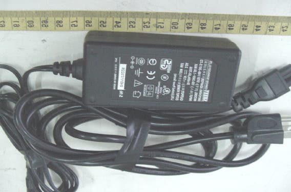
ETC Report No. : ET93R-08-021-01 Sheet 1 of 28 Sheets FCC ID.: QZG5113R Rev. No 2.0 CONSTRUCTED PHOTOS of EUT A. 1.Top View of EUT 2. Front View of EUT SL5113R SL5113R ETC Report No. : ET93R-08-021-01 Sheet 2 of 28 Sheets FCC ID.: QZG5113R Rev. No 2.0 CONSTRUCTED PHOTOS of EUT 3. Side View of EUT 4. Rear View of EUT SL5113R SL5113R ETC Report No. : ET93R-08-021-01 Sheet 3 of 28 Sheets FCC ID.: QZG5113R Rev. No 2.0 CONSTRUCTED PHOTOS of EUT 5. Side View of EUT 6. Bottom View of EUT SL5113R SL5113R ETC Report No. : ET93R-08-021-01 Sheet 12 of 28 Sheets FCC ID.: QZG5113R Rev. No 2.0 CONSTRUCTED PHOTOS of EUT B. ODU 1. Side View of ODU 2. Bottom View of ODU SL5113R SL5113R ETC Report No. : ET93R-08-021-01 Sheet 13 of 28 Sheets FCC ID.: QZG5113R Rev. No 2.0 CONSTRUCTED PHOTOS of EUT 3. TOP View of ODU 4. Side View of ODU SL5113R SL5113R ETC Report No. : ET93R-08-021-01 Sheet 14 of 28 Sheets FCC ID.: QZG5113R Rev. No 2.0 CONSTRUCTED PHOTOS of EUT 5. Side View of ODU 6. Side View of ODU SL5113R SL5113R ETC Report No. : ET93R-08-021-01 Sheet 26 of 28 Sheets FCC ID.: QZG5113R Rev. No 2.0 CONSTRUCTED PHOTOS of EUT C. Adaptor 1. Front View of Adaptor 2. Rear View of Adaptor
ID Label/Location Info
910805 5 ID LABEL ODU Front IDU Outdoor Unit 2.4GHz Radio Unit A H/W:v2.02 F/W:v2.02 FCC ID:QZG5113R E1 Spread Spectrum Radios SL1234567890 4cm 2.5cm Indoor Unit 2E1 RJ-48 Modem H/W:v5.01 F/W:v5.01 FCC ID:QZG5113R E1 Spread Spectrum Radios SL1234567890 2.5cm Side
Internal Photos
ETC Report No. : ET93R-08-021-01 Sheet 4 of 28 Sheets FCC ID.: QZG5113R Rev. No 2.0 CONSTRUCTED PHOTOS of EUT 7. Internal View of EUT SL5113R ETC Report No. : ET93R-08-021-01 Sheet 5 of 28 Sheets FCC ID.: QZG5113R Rev. No 2.0 CONSTRUCTED PHOTOS of EUT 8. Component View of Main PCB 9. Solder View of Main PCB SL5113R SL5113R ETC Report No. : ET93R-08-021-01 Sheet 6 of 28 Sheets FCC ID.: QZG5113R Rev. No 2.0 CONSTRUCTED PHOTOS of EUT 10. Component View of PCB 11. Component View of PCB SL5113R SL5113R ETC Report No. : ET93R-08-021-01 Sheet 7 of 28 Sheets FCC ID.: QZG5113R Rev. No 2.0 CONSTRUCTED PHOTOS of EUT 12. Solder View of PCB 13. Component View of PCB SL5113R SL5113R ETC Report No. : ET93R-08-021-01 Sheet 8 of 28 Sheets FCC ID.: QZG5113R Rev. No 2.0 CONSTRUCTED PHOTOS of EUT 14. Solder View of PCB 15. Component View of PCB SL5113R SL5113R ETC Report No. : ET93R-08-021-01 Sheet 9 of 28 Sheets FCC ID.: QZG5113R Rev. No 2.0 CONSTRUCTED PHOTOS of EUT 16. Solder View of PCB 17. Solder View of PCB SL5113R SL5113R ETC Report No. : ET93R-08-021-01 Sheet 10 of 28 Sheets FCC ID.: QZG5113R Rev. No 2.0 CONSTRUCTED PHOTOS of EUT 18. Component View of PCB 19. Solder View of PCB SL5113R SL5113R ETC Report No. : ET93R-08-021-01 Sheet 11 of 28 Sheets FCC ID.: QZG5113R Rev. No 2.0 CONSTRUCTED PHOTOS of EUT 20. Component View of PCB 21. Solder View of PCB SL5113R SL5113R ETC Report No. : ET93R-08-021-01 Sheet 15 of 28 Sheets FCC ID.: QZG5113R Rev. No 2.0 CONSTRUCTED PHOTOS of EUT 7. Internal View of ODU 8. Internal View of ODU SL5113R SL5113R ETC Report No. : ET93R-08-021-01 Sheet 16 of 28 Sheets FCC ID.: QZG5113R Rev. No 2.0 CONSTRUCTED PHOTOS of EUT 9. Front View of RF Module 10. Rear View of RF Module SL5113R SL5113R ETC Report No. : ET93R-08-021-01 Sheet 17 of 28 Sheets FCC ID.: QZG5113R Rev. No 2.0 CONSTRUCTED PHOTOS of EUT 11. Component View of ODU’s PCB 12. Solder View of ODU’s PCB SL5113R SL5113R ETC Report No. : ET93R-08-021-01 Sheet 18 of 28 Sheets FCC ID.: QZG5113R Rev. No 2.0 CONSTRUCTED PHOTOS of EUT 13. Component View of ODU’s PCB 14. Component View of ODU’s PCB SL5113R SL5113R ETC Report No. : ET93R-08-021-01 Sheet 19 of 28 Sheets FCC ID.: QZG5113R Rev. No 2.0 CONSTRUCTED PHOTOS of EUT 15. Solder View of ODU’s PCB 16. Component View of ODU’s PCB SL5113R SL5113R ETC Report No. : ET93R-08-021-01 Sheet 20 of 28 Sheets FCC ID.: QZG5113R Rev. No 2.0 CONSTRUCTED PHOTOS of EUT 17. Solder View of ODU’S PCB 18. Component View of ODU’s PCB SL5111R SL5113R ETC Report No. : ET93R-08-021-01 Sheet 21 of 28 Sheets FCC ID.: QZG5113R Rev. No 2.0 CONSTRUCTED PHOTOS of EUT 19. Solder View of ODU’s PCB 20. Component View of ODU’s PCB SL5113R SL5113R ETC Report No. : ET93R-08-021-01 Sheet 22 of 28 Sheets FCC ID.: QZG5113R Rev. No 2.0 CONSTRUCTED PHOTOS of EUT 21. Solder View of ODU’s PCB 22. Component View of ODU’s PCB SL5113R SL5113R ETC Report No. : ET93R-08-021-01 Sheet 23 of 28 Sheets FCC ID.: QZG5113R Rev. No 2.0 CONSTRUCTED PHOTOS of EUT 23. Solder View of ODU’s PCB 24. Component View of ODU’s PCB SL5113R SL5113R ETC Report No. : ET93R-08-021-01 Sheet 24 of 28 Sheets FCC ID.: QZG5113R Rev. No 2.0 CONSTRUCTED PHOTOS of EUT 25. Solder View of ODU’s PCB 26. Component View of ODU’s PCB SL5113R SL5113R ETC Report No. : ET93R-08-021-01 Sheet 25 of 28 Sheets FCC ID.: QZG5113R Rev. No 2.0 CONSTRUCTED PHOTOS of EUT 27. Solder View of ODU’s PCB SL5113R ETC Report No. : ET93R-08-021-01 Sheet 27 of 28 Sheets FCC ID.: QZG5113R Rev. No 2.0 CONSTRUCTED PHOTOS of EUT 3. Internal View of Adaptor ETC Report No. : ET93R-08-021-01 Sheet 28 of 28 Sheets FCC ID.: QZG5113R Rev. No 2.0 CONSTRUCTED PHOTOS of EUT 4. Component View of Adaptor’s PCB 5. Solder View of Adaptor’s PCB
Operational Description
TEL: +886-2-2910-5038 FAX: +886-2-2910-5048 http://www.kbest.com.tw E-mail: [email protected] or [email protected] E1 Point to Point Digital Radios is an emerging wireless telecommunication technology which combines high frequency microwave technology, digital modulation and demodulation technology, computer control and telecommunication technology. It has been used widely in the aspects of post, electricity, academics, various enterprises, military, and professional systems especially for connecting between base stations of mobile communication. As an approach of rapid connection, it could also been used in emergency and urgent communication widely. It is fast to setup, and can be deployed with great ease during urgent times when the need for communication is imminent. The E1 PTP Digital Radios of K-best technology could be operated in the frequency of ISM 2.4GHz, 5.8GHz and could be customized according to customer’s need…
Text truncated - open the document above for the full version.
Contact Information
Applicant
Yu-Wei Tung(General Manager)
Test Firm
Electronics Testing Center, TaiwanWin-Po Tsai
Technical Specifications
| # | Rule Parts | Frequency Range | Power Output |
|---|---|---|---|
| 2 | 15C | 5.82 GHz - 5.84 GHz | 155.00 mW |
Other Applications from K-Best Technology Inc.
QZGBL5201-001
Apr 07, 2005802.11g Outdoor HotSpot
Equipment Class
DTS - Digital Transmission System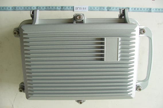
QZG5111R
Mar 23, 2005E1 Spread Spectrum Radios
Equipment Class
DTS - Digital Transmission System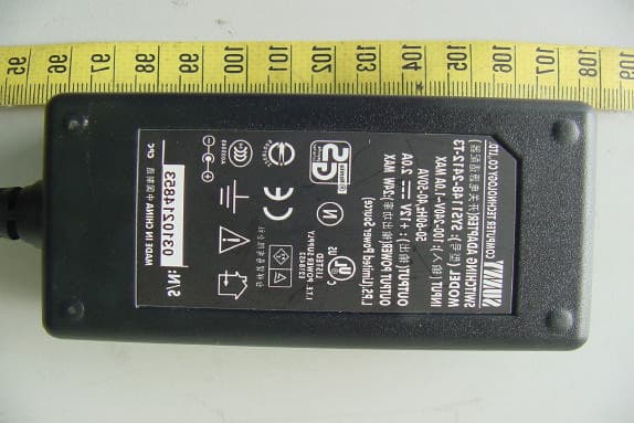
QZGBL4001-001
Jan 17, 2005BL4000 2.4GHz WLAN ODU
Equipment Class
DTS - Digital Transmission System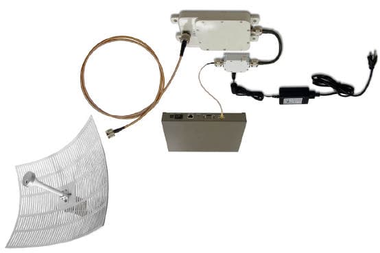
QZGKBW2458-001
May 03, 2004KBW58 Converter With NDC WLAN Access Point
Equipment Class
DTS - Digital Transmission System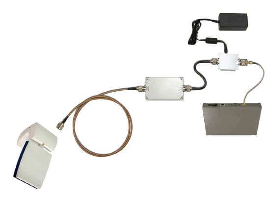
QZGKBW24-001
May 03, 2004KBW24 Booster With NDC WLAN Access Point
Equipment Class
DTS - Digital Transmission System