QZGKBW24-001KBW24 Booster With NDC WLAN Access Point
K-Best Technology Inc.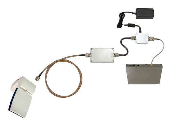
Click to zoom
Application Details
- Equipment Class
- DTS - Digital Transmission System
- Date of Grant
- May 03, 2004
- Application Purpose
- Original Equipment
- Date of Application
- May 03, 2004
- Equipment Note
- KBW24 Booster With NDC WLAN Access Point
- Frequency Range
- 2412.00000000 - 2462.00000000
- Company
- K-Best Technology Inc.
- Country
- Taiwan
Documents & Files
Document Text
Text extracted from the exhibit documents filed with the FCC. Open a document above to read the original.
Users Manual
Booster Installation Guide Version 1.2 KBEST Technology Copyright Copyright © 2003 all rights reserved. No part of this publication may be reproduced, adapted, stored in a retrieval system, translated into any language, or transmitted in any form or by any means without the written permission of the supplier. About This Manual The purpose of this manual is for the setup of Booster & DC Injector. This manual, revised as version 1.2 in 2003, includes the procedures to assist you in avoiding unforeseen problems. Technical Support If you have difficulty resolving the problem while installing or using the Booster & DC Injector, please contact the supplier for support. FCC Notice Reminder: To comply with FCC part 15 rules, the Booster must only be used as a system as FCC certified. The system must also be professionally installed to ensure compliance with the Part 15 certification. It is the responsibility of the operator and professional installer to ensure that only certified systems are deployed in where FCC rules apply. Further, according to FCC Part 15 regulations, Section 15.247(b)(3)(iii), the installer must ensure that the high-gain directional antenna used in this system is used exclusively for fixed, point-to-point operations and that multiple co-located intentional radiators transmitting the same information are not used. For further information, please see Appendix B. FCC Certified Declaration: This device complies with part 15 of the FCC rules. Operation is subject to the following two conditions: (1) This device may not cause harmful interference and (2) this device must accept any interference received, including interference that may cause undesired operation. Table of Contents Chapter 1 Introduction..........................................................5 1-1 Product Kit.............................................................................................5 1-2 Features and Benefits........................................................................6 1-3 Specifications........................................................................................7 1-4 Calculate Transmit Power.................................................................9 1-5 Installing the Booster Kit................................................................11 Appendix A: Channel Plans....................................................................13 Appendix B: FCC Certified Systems...................................................14 Appendix C: Troubleshooting................................................................16 5 Chapter 1 Introduction K-Best’s Booster, operating on the 2.4GHz ISM band, is a high performance two-way amplifier using Time Division Duplex (TDD) technology. It is used outdoor to extend the range of wireless radio communication. K-Best’s DC injector (KBDC24E) functions as a provider of DC power to the outdoor booster or transponder through the feed cable without an additional power cord. The DC injector comes with different types of connector upon custom’s request . The standard product of KBDC24E-2N is equipped with female N type at both side, and KBDC24E-AN with female N type at one side and female SMA at another side. 1-1 Product Kit Before installation, make sure that you the following items: Booster DC Injector Jumper Cable Power Adapter Installation Guide NDC Access Point and adapter cable 6 1-2 Features and Benefits 2400~2500 MHz unlicensed ISM Band Provides DC Power to the booster without an additional Power cord Booster has 1W output power levels. 20dB(1W) receive gain for the booster Bi-directional TDD technology Transmitter and receiver LED indicator Waterproof housing Compatible with IEEE 802.11b Extending transmission distance Enhance signal strength 7 1-3 Specifications Specifications for DC Injector Operating Frequency Range 2400~2500MHz Bias Current / DC Voltage / Insertion Loss 1.5A (max.) / 15V (max.) / 1dB Connector / DC Jack N type female for both side / φ 6 mm, center pin φ 2.0 mm Dimensions / Weight 99.1(H)x53.5(W)x21.2(H)mm / 165g Specifications for Booster Operating Frequency Range / 2400~2500MHz Operating Mode Bi-directional TDD Transmitter Output Power / Transmitter Gain 30 dBm Typical / automatically adjusts to 1W power output Transmitter Input Power Max: 13 dBm Min: 3 dBm Receiver Input Power Max: -16 dBm Receiver Gain 20dB Frequency Response Flatness ± 1dB over operating range Noise Figure < 4 dB Switch Time < 1.5 μs Connector N-type Female (50Ω); SMA connector available for custom design Operating Temperature -30~60°C 8 Power Consumption 1watt, 950mA @ 9VDC LED Indication Transmit: Green; Receive: Red Dimensions / Weight 120(L)x72(W)x17.5(H) mm / 380g 9 1-4 Calculate Transmit Power In order to obtain the best performance of booster and system, user must calculate the transmission power to meet the booster technical requirement and FCC regulations(See Appendix B). It is advised that the user follows the calculation below: 1. Converter power of the access point from milliwatts to dBm. Note: dBm = 10 * Log(milliwatts) 2. Determine the attenuation of cable(please refer to manufacturer’s specifications) Note: Suggest the cable loss between booster and DC injector should not exceed 10 dBm generally. Table A – Typical Cable Attenuation Values Cable Type Attenuation dB/100ft @2.4GHz RG-142 21 LMR200 16.5 LMR400 6.6 LMR600 4.4 LMR900 2.92 Belden 9913 7.1 Note: Values are approximate. 10 3. Calculate the actual power of booster in the pole as follow: Access point Power(dBm) – Cable Loss(dBm) – Misc. Loss = Input Signal Level(dBm) Note: Misc. Loss means loss of connector, adapter and DC injector and estimates to be around 2 dB. 4. If the input signal level exceeds the max. Transmitter Input Power or fails to meet the min. Transmitter Input Power of booster, the booster can’t identify the input signal. Under this circumstance, user should adjust the input signal level to fit the requirement such as …
Text truncated - open the document above for the full version.
Users Manual
High Speed Access Point User’s Guide P/N.: 85-506600-00 Rev.X1 May 2000 NDC Communications, Inc. 265 Santa Ana Court Sunnyvale, CA 94086, USA Tel: +1 (408) 730-0888 Fax: +1 (408) 730-0889 Technical Support E-mail: [email protected] (US only) Toll-Free (US only): 800-632-1118 Europe and Asia Pacific E-mail: [email protected] NDC World Wide Web www.ndclan.com ii InstantWave High Speed Access Point TRADEMARKS NDC and SOHOware are trademarks of NDC Communications, Inc. All other names mentioned in this document are trademarks/registered trademarks of their respective owners. NDC provides this document "as is," without warranty of any kind, neither expressed nor implied, including, but not limited to, the particular purpose. NDC may make improvements and/or changes in this manual or in the product(s) and/or the program(s) described in this manual at any time. This document could include technical inaccuracies or typographical errors. FCC WARNING This equipment has been tested and found to comply with the limits for a Class B Digital device, pursuant to part 15 of the FCC Rules. These limits are designed to provide reasonable protection against harmful interference in a residential installation. This equipment generates, uses, and can radiate radio frequency energy and, if not installed and used in accordance with the instructions, may cause harmful interference to radio communications. However, there is no guarantee that interference will not occur in a particular installation. If this equipment does cause harmful interference to radio or television reception, which can be determined by turning the equipment off and on, the user is encouraged to try to correct the interference by one or more of the following measures: ü Reorient or relocate the receiving antenna ü Increase the separation between the equipment and receiver ü Connect the equipment into an outlet on a circuit different from that to which the receiver is connected ü Consult the dealer or an experienced radio/TV technician for help You are cautioned that changes or modifications not expressly approved by the party responsible for compliance could void your authority to operate the equipment. This device complies with part 15 of the FCC Rules. Operation is subject to the following two conditions: 1. This device may not cause harmful interference, and 2. This device must accept any interference received, including interference that may cause undesired operation InstantWave High Speed Access Point iii Table Of Contents PACKING LIST........................................................................................................................................................................VIII INTRODUCTION..........................................................................................................................................................................1 INSTANTWAVE FAMILY................................................................................................1 SYSTEM REQUIREMENTS.............................................................................................1 CABLING..............................................................................................................................1 GLOSSARY.........................................................................................................................................................................................2 HOW TO USE THIS GUIDE..............................................................................................................................................3 PLANNING YOUR NETWORK....................................................................................................................................4 INFRASTRUCTURE NETWORK TYPES.....................................................................4 PLANNING AN INFRASTRUCTURE NETWORK....................................................6 Single AP Installation..................................................................................................6 Multiple APs Installation.............................................................................................6 ROAMING.............................................................................................................................7 ACCESS POINT PLACEMENT GUIDELINES............................................................8 Placing For Performance.............................................................................................8 Placement Tools............................................................................................................8 MOUNTING THE AP.........................................................................................................8 GETTING STARTED.................................................................................................................................................................9 ACCESS POINT HARDWARE INSTALLATION.......................................................9 LED INDICATORS...........................................................................................................10 AP MANAGEMENT SOFTWARE INSTALLATION / UNINSTALLATION....11 Installation....................................................................................................................11 Uninstallation...............................................................................................................11 AP COMFIG TOOL.................................................................................................................................................................13 USING THE AP COMFIG TOOL...................................................................................13 AP COMFig Password...............................................................................................13 iv InstantWave High Speed Access Point AP COMFig Service....................................…
Text truncated - open the document above for the full version.
Cover Letter(s)
1 Mike Kuo From: S. S. Liou Sent: November182003Tuesday 12:04 AM To: Mike Kuo Subject: Re: K-Best Technology Inc., FCC ID:QZGKBW24-001, AN03T3214 Revised User Manual.pdf Theory of Operation.PDF Exhibit-A-Block_Dia gram_revise... Schematics of AP.pdf Internal photos of AP.pdf Users Manual of AP.pdf Exhibit-C-Test_Rep ort_revised.... Hi Mike, This is the reply for AN03T3214. Ans. #1: please refer to revised user manual page 14. Ans. #2: please refer to revised user manual page 3. Ans #3: please refer to theory of operation and revised block diagram. Ans. #4: female N type connector. Ans. #5: please refer to schematic diagram, internal photo and user manual of AP. Ans. #6: TDD technology used. Please refer to revised user manual page 5. Ans. #7: data rate is the same as input 2.4GHz signal. Output power is 1W max. Ans. #8: please refer to revised user manual, the inadequate description is removed. Ans. #9: the input power from AP is 13dBm. The acceptable input power ranges from 3 to 13 dBm. Please refer to revised user manual page 7. Ans. #10 - 12: please refer to revised test report. There are some typing mistakes in the former test report. Ans. #13: please refer to revised user manual page 3. Best regards, ================================ S. S. Liou Engineer / EMC Dep. II ETC ----- Original Message ----- From: "Mike Kuo" <[email protected]> To: "Will Yauo ; "ETC/Iris (E-mail)" Sent: Wednesday, September 24, 2003 3:28 PM Subject: FW: K-Best Technology Inc., FCC ID:QZGKBW2458-001, AN03T3213 > Hi Will: Another K-Best application AN03T3214 has same type of questions. > Please consider the questions posted for AN03T3213 apply to AN03T3214 > > -----Original Message----- > From: CERTADM > Sent: Wednesday, September 17, 2003 12:15 PM > To: '[email protected]' > Subject: K-Best Technology Inc., FCC ID:QZGKBW2458-001, AN03T3213 > > > Notice_content > ------------- > Question #1: Please provide antenna specification for all the antennas that > are intended to be used with this device. Information shall include but > not limit to : Manufacturer name, model no/name, type of antenna ( dipole , > panel etc. ), type of operation ( PTP or PTM ), antenna gain, and the cable 2 > length requirements. > > Question #2: Per section 15.204(a) of FCC rules, external radio frequency > power amplifier can not be sold as stand alone unit to be used with > unlicensed transmitter. 15.204(b) indicates that external radio frequency > power amplifier can only be sold as complete system. As indicated n the > test report, this device was tested with FCC ID:IOU0660S02 access point. > This is the only information which disclose the type of access point will be > used with this device. In the user manual, there is no place indicate how > the applicant can comply 15.204(b) requirement. Please provide marketing > statement, revise user manual to provide additional information to address > 15.204(b) requirements. > > Question #3: The information contains in the operational description do not > provide any technical information to explain how the output power of device > will be limited to 200mW and the frequency conversion process. Please > provide detail theory of operation to explain the entire system. > > Question #4: Please provide the antenna connector type used on the device. > > Question #5: Please provide schematic diagram, internal photo and theory of > operation of Access point. > > Question #6: What type of modulation during 5GHz operation ? > > Question #7: What is the data rate during 5GHz operation and the high output > power in each data rate. > > Question #8: As indicate in page 4 of user manual, this converter can be > used for Wireless Local Loop, WLAN and Wireless Internet Access as well. > Please provide technical information to explain the type of device will be > connected to this converter for all above services. > > Question #9:What is the input power from Access Point to the convert during > the RF conducted and Radiated emission tests ? > > Question #10: Page 20 - 22 radiated emission tests in restricted band: there > are many identical frequency with identical field strength with different > antenna. Please explain why the antenna gain and pattern are different but > measured with nearly identical field strength . > > Question #11: Page 23-25 radiated data below 1GHz demonstrated same > questions as Question #10. Please explain. > > Question #12: RF conducted spurious emission was measured with RBW=1MHz. > Per FCC guideline in measuring DTS device, RF conducted spurious emission > shall be measured with RBW=100kHz. Please redo the measurement and provide > additional test data. > > Question #13: User Manual does not include RF exposure information. Please > provide revised user manual. > > Best Regards > > Mike Kuo > The items indicated above must be submitted before processing can continue > on the above referenced application. Failure to provide the requested > information within 30 days of the original e-mail date may result in > application dismissal and forfeiture of the filing fee. Also, please note > that partial responses increase processing time and should not be submitted. 3 > > Any questions about the content of this correspondence should be > directed to the e-mail address listed below the name of the sender.
Cover Letter(s)
Mike Kuo From: S. S. Liou Sent: April21 2004 Wednesday 6:29 AM To: Mike Kuo Cc: R00/ Subject: Re: K -Best FCC Importance: High 5/4/2004 Dear Mike, Reply 1) & 2): Please refer to attached FCCID label format and location of both applications. Reply 3): Please refer to attached marketing statement of both applications. Reply 4) & 7): Please refer to attached revised user manual of both applications. Reply 5): Please refer to attached system photo of both applications. Reply 6): Please refer to attached MPE evaluation of both applications. Please issue the grants again soon. Thank you very much! Best regards, ================================ S. S. Liou Engineer / EMC Dep. II ETC Hi Mr. Liou : I have confirmation from FCC what need to be done in order to refile the applications . Below are the action items : The following action items are applicable to K-Best FCC ID:QZGKBW2458-001 and QZGKBW24-001. 1) Provide revised FCC ID label format with correct FCC ID number listed for both applications 2) Provide FCC ID label location. FCC ID label shall be placed on the amplifier , the NDC access point and DC injector ( K- Best FCC ID label will be covered the FCC ID label for NDC ). Submit FCC ID label location to show K-Best is going to have FCC ID label of QZGKBW2458-001 and QZGKBW24-001 on the amplifier, access point and DC injector 3) K-Best issue a marketing statement under K-Best letter to declare that FCC ID:QZGKBW2458-001 and QZGKBW24-001 will only be sold as complete system. Access Point, amplifier and DC injector will not be sold individually. 4) Modify User manual, "NDC Access Point and adapter cable (purchased together or separately)" - per 15.204 separately is not an option. Delete the option to allow the user to purchase NDC access point and adapter cable separately. 5) Take a external photos to show all component connected together as a system 6) MPE RF exposure compliance. Based upon my calculation, the separation distance requires should be 71 cm. Please provide MPE estimate or MPE test report to show by increasing the distance the power density will not be increased. 7) Modify User manual to include required separation distance. Best Regards Mike Kuo From: Mike Kuo [mailto:[email protected]] Sent: Friday, April 02, 2004 3:09 PM To: Tim Harrington Subject: RE: pt15 amp sys Hi Tim: O.K. I will call you around 4:00 pm your time. By reviewing the questions listed in your dismissal letter, please allow me to address each question in advance : 1) System FCC ID label is required on the main control unit ( access point ) Reply : under discussion. 2) Please include clear, close-up external photos exhibits of entire system with all components connected together for representative configuration ( not poorly lit or far away test setup photo ) Reply : Page 11 of user manual has included configuration setup diagram to show how each component will be connected together. If you require to have external photos to be taken by the test lab, I will make such request to the test lab and provide such photos. 3) MPE evaluation and related antenna installation need revision - power density shows increase with distance - need to continue evaluation out to farther distances. Reply : It is my mistake. Based upon MPE calculation ( estimate ), the required separation distance should be 1 meter not 20 cm as indicated on the grant. The user manual shall include such requirement in the user manual. 4) FCC ID label appears to have paste-in letters - please revise Reply : K-Best has two grantee code assigned. One is QW4 and the other one is QZG. The paste-in is to change the grantee code from QW4 to QZG. I will ask the grantee to provide revised FCC ID label. Best Regards Mike Kuo -----Original Message----- From: Tim Harrington [mailto:[email protected]] Sent: Friday, April 02, 2004 11:28 AM To: Mike Kuo Subject: RE: pt15 amp sys please give me at least 1 to 1.5 hours to check those before you call From: Mike Kuo [mailto:[email protected]] Sent: Friday, April 02, 2004 2:26 PM To: Tim Harrington Subject: RE: pt15 amp sys Hi Tim: The reference FCC ID number that I used while reviewing K-Best application is FCC ID:OQCWAF24-1000L which is granted by FCC and reviewed by Joe. In this application, the FCC ID label is located on the amplifier . 5/4/2004 I also certified another similar Part 15C external amplifier and was audited by Mike Nicolay under FCC ID:OJFMODULITE810 . During audit review, Mike did not ask the FCC ID label to be placed on Cisco Access Point. I reviewed the FCC ID numbers that you provided. It is true that TCB requires the FCC ID number to be covered up on the PCMCIA card or Cisco Access Point, but it is not necessary is the Commission's requirement. In addition, I do not think NM5, P6G or MYF grantee will have any control on the design changes that may be made on Cisco or Proxim WLAN card. I will give you a call. Best Regards Mike Kuo -----Original Message----- From: Tim Harrington [mailto:[email protected]] Sent: Friday, April 02, 2004 10:12 AM To: Mike Kuo; Tim Harrington Subject: pt15 amp sys NM5LUC2400E P6GWLERFA P6GWLERVA MYF-G11FNFPCX 5/4/2004
External Photos
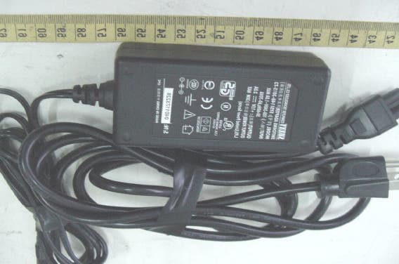
ETC Report No. : ET92R-08-036 FCC ID.: QZGKBW24-001 Rev. No 2.0 CONSTRUCTED PHOTOS of EUT Top View of EUT Bottom View of EUT ETC Report No. : ET92R-08-036 FCC ID.: QZGKBW24-001 Rev. No 2.0 CONSTRUCTED PHOTOS of EUT Front View of EUT Rear View of EUT ETC Report No. : ET92R-08-036 FCC ID.: QZGKBW24-001 Rev. No 2.0 ONSTRUCTED PHOTOS of EUT Side View of EUT Side View of EUT ETC Report No. : ET92R-08-036 FCC ID.: QZGKBW24-001 Rev. No 2.0 CONSTRUCTED PHOTOS of EUT Top View of EUT Bottom View of EUT ETC Report No. : ET92R-08-036 FCC ID.: QZGKBW24-001 Rev. No 2.0 CONSTRUCTED PHOTOS of EUT Front View of EUT Rear View of EUT ETC Report No. : ET92R-08-036 FCC ID.: QZGKBW24-001 Rev. No 2.0 CONSTRUCTED PHOTOS of EUT Side View of EUT Side View of EUT ETC Report No. : ET92R-08-036 FCC ID.: QZGKBW24-001 Rev. No 2.0 CONSTRUCTED PHOTOS of EUT Front View of Adaptor Rear View of Adaptor ETC Report No. : ET92R-08-036 FCC ID.: QZGKBW24-001 Rev. No 2.0 CONSTRUCTED PHOTOS of EUT Side View of Adaptor Side View of Adaptor
External Photos
QZGKBW24-001
ID Label/Location Info
910805 1 K-Best Technology 2.4GHz 1W WLAN Booster Model No.KBW24-101 FCC ID:QZGKBW24-001 2410020413xxxx Barcode label FCC K-Best Technology 2.4GHz 1W WLAN Booster Model No.BL1002N FCC ID:QZGKBW24-001 111111111111111111 2410020413xxxx 910805 2 FCC IDENTIFICATION LABEL TO BE PLACED HERE 910805 1 FCC IDENTIFICATION LABEL TO BE PLACED HERE
Internal Photos
ETC Report No. : ET92R-08-036 FCC ID.: QZGKBW24-001 Rev. No 2.0 CONSTRUCTED PHOTOS of EUT Internal View of EUT ETC Report No. : ET92R-08-036 FCC ID.: QZGKBW24-001 Rev. No 2.0 CONSTRUCTED PHOTOS of EUT Component View of PCB 1 Solder View of PCB 1 ETC Report No. : ET92R-08-036 FCC ID.: QZGKBW24-001 Rev. No 2.0 CONSTRUCTED PHOTOS of EUT Internal View of EUT ETC Report No. : ET92R-08-036 FCC ID.: QZGKBW24-001 Rev. No 2.0 CONSTRUCTED PHOTOS of EUT Component View of PCB Solder View of PCB ETC Report No. : ET92R-08-036 FCC ID.: QZGKBW24-001 Rev. No 2.0 CONSTRUCTED PHOTOS of EUT Front View of Antenna Rear View of Antenna ETC Report No. : ET92R-08-036 FCC ID.: QZGKBW24-001 Rev. No 2.0 CONSTRUCTED PHOTOS of EUT Internal View of Adaptor ETC Report No. : ET92R-08-036 FCC ID.: QZGKBW24-001 Rev. No 2.0 CONSTRUCTED PHOTOS of EUT Component View of Adaptor’s PCB Solder View of Adaptor’s PCB ETC Report No. : ET92R-08-036 FCC ID.: QZGKBW24-001 Rev. No 2.0 CONSTRUCTED PHOTOS of EUT Component View of Adaptor’s PCB Solder View of Adaptor’s PCB
Operational Description
According to the block diagram, the converter has AGC circuit that can lock the output at a constant level. Simultaneously, when the input signal exceeds the dynamic range, the circuit's attenuator will automatically attenuate within the limit of the output level.
RF Exposure Info
FCC ID: QZGKBW24-001 RF Exposure Evaluation of E.U.T. : KBW24 Booster with NDC WLAN Access Point FCC ID. : QZGKBW24-001 MODEL : KBW24-101 for APPLICANT : K-Best Technology Inc. ADDRESS : 2F1, -1, No. 185, Ko Wang Rd., Kau Yuan Tsun, Lung Tan Hsiang, Tao Yuan Hsien, Taiwan Prepared by ELECTRONICS TESTING CENTER, TAIWAN NO. 34, LIN 5, DING FU TSUN, LINKOU HSIANG, TAIPEI HSIEN, TAIWAN, R.O.C. Tel:(02)26023052 Fax:(02)26010910 http://www.etc.org.tw ; e-mail: [email protected] Report Number : ET92R-08-036 FCC ID: QZGKBW24-001 Product Information: Type of EUT: KBW24 Booster with NDC WLAN Access Point FCC ID: QZGKBW24-001 Manufacturer: K-Best Technology Inc. Model: KBW24-101 Description: 1. 2400~2500 MHz unlicensed ISM Band 2. Provides DC Power to the booster without an additional Power cord 3. Booster has 0.5/1W output power levels. 4. 20 dB receive gain for the booster 5. Bi-directional TDD technology 6. Transmitter and receiver LED 7. Waterproof housing 8. The NDC WLAN Access Point is currently certified with FCC ID: IOU0660S02 Maximum conducted output power (measured): 29.8 dBm or 954.14 mW The following table lists the provided authorized antennas: Antenna Gain Model Antenna Type (dBi) Numeric KBNT2406-01 Flat Panel 6 3.98 Below is an example of the RF Exposure Statement: Notice: To comply with the FCC RF exposure compliance requirements, the antenna(s) used for this transmitter must be installed to provide a separation distance of at least 20 cm from all persons and must not be co-located or operating in conjunction with any other antenna or transmitter. No change to the antenna or the device is permitted. Any change to the antenna or the device could result in the device exceeding the RF exposure requirements and void user's authority to operate the device. FCC ID: QZGKBW24-001 Relative Requirement for Compliance According to section 1.1310 of FCC 47 CFR Part 1, limits for maximum permissible exposure (MPE) are as following: TABLE 1 – LIMITS FOR MAXIMUN PERMISSIBLE EXPOSURE (MPE) Frequency Range (MHz) Electric Field Strength (V/m) Magnetic Field Strength (A/m) Power Density (mW/cm 2 ) Averaging Time (minutes) (A) Limits for Occupational/Controlled Exposures 0.3-3.0 .................. 614 1.63 *(100) 6 3-30 ..................... 1842/f 4.89/f *(900/f 2 ) 6 30-300 .................. 61.4 0.163 1.0 6 300-1500 ............... ...................... ...................... f/300 6 1500-100,000 ......... ...................... ...................... 5 6 (B) Limits for General Population/Uncontrolled Exposure 0.3-1.34 ............... 614 1.63 *(100) 30 1.34-30 ............... 824/f 2.19/f *(180/f2) 30 30-300 .................. 27.5 0.073 0.2 30 300-1500 ............... ...................... ...................... f/1500 30 1500-100,000 ......... ...................... ...................... 1.0 30 f = frequency in MHz * = Plane-wave equivalent power density NOTE 1 TO TABLE 1: Occupational/controlled limits apply in situations in which persons are exposed as a consequence of their employment provided those persons are fully aware of the potential for exposure and can exercise control over their exposure. Limits for occupational/controlled exposure also apply in situations when an individual is transient through a location where occupational / controlled limits apply provided he or she is made aware of the potential for exposure. NOTE 2 TO TABLE 1: General population/uncontrolled exposures apply in situations in which the general public may be exposed, or in which persons that are exposed as a consequence of their employment may not be fully aware of the potential for exposure or can not exercise control over their exposure. FCC ID: QZGKBW24-001 RF Exposure Calculations: The following information provides the minimum separation distance for the highest gain antenna provided. This calculation is based on the highest EIRP possible from the system, considering maximum power and antenna gain, and considering a 1.0 mW/cm 2 uncontrolled exposure limit. The formula shown in OET Bulletin 65 is used in the calculation. Equation from page 19 of OET Bulletin 65, Edition 97-01 is: S= PG / 4R 2 where: S = power density (in appropriate units, e.g. mW/cm 2 ) P = power input to the antenna (in appropriate units, e.g., mW) G = power gain of the antenna in the direction of interest relative to an isotropic radiator R = distance to the center of radiation of the antenna (appropriate units, e.g., cm) hence R= PG / 4S) 1/2 For our device P = 954.14 mW G = 3.98 S = Exposure limit = 1.0 mW/cm 2 R = ((954.14 * 3.98) / (4**1.0)) 1/2 = 17.38 cm For complying the FCC limits for general population/uncontrolled exposure, the minimum MPE distance is 17.38 cm.
Test Report
Rev. No 2.0 FCC Part 15 EMI TEST REPORT of E.U.T. : KBW24 Booster with NDC WLAN Access Point FCC ID. : QZGKBW24-001 MODEL : KBW24-101 for APPLICANT: K-Best Technology Inc. ADDRESS: 2F1, -1, No. …
Text truncated - open the document above for the full version.
Contact Information
Applicant
Yu-Wei Tung(General Manager)
Test Firm
Electronics Testing Center, TaiwanWill Yauo
Technical Specifications
| # | Rule Parts | Frequency Range | Power Output |
|---|---|---|---|
| 1 | 15C | 2.41 GHz - 2.46 GHz | 954.00 mW |
Other Applications from K-Best Technology Inc.
QZGBL5201-001
Apr 07, 2005802.11g Outdoor HotSpot
Equipment Class
DTS - Digital Transmission System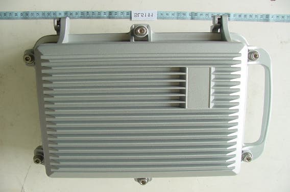
QZG5111R
Mar 23, 2005E1 Spread Spectrum Radios
Equipment Class
DTS - Digital Transmission System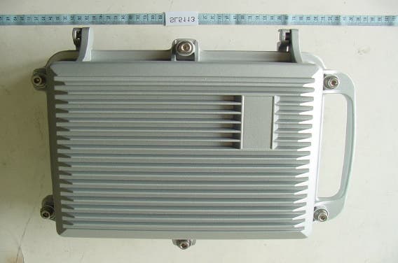
QZG5113R
Mar 23, 2005E1 Spread Spectrum Radios
Equipment Class
DTS - Digital Transmission System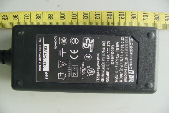
QZGBL4001-001
Jan 17, 2005BL4000 2.4GHz WLAN ODU
Equipment Class
DTS - Digital Transmission System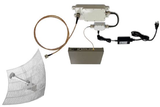
QZGKBW2458-001
May 03, 2004KBW58 Converter With NDC WLAN Access Point
Equipment Class
DTS - Digital Transmission System