R2L2110KEYAccess Control Unit
XceedID Corporation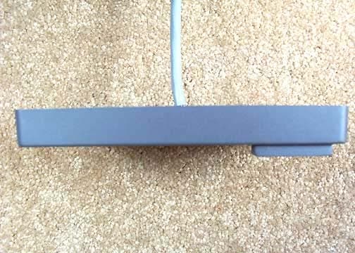
Click to zoom
Application Details
- Equipment Class
- DXT - Part 15 Low Power Transceiver, Rx Verified
- Date of Grant
- Dec 12, 2004
- Application Purpose
- Original Equipment
- Date of Application
- Dec 12, 2004
- Equipment Note
- Access Control Unit
- Frequency Range
- 13.56000000 - 13.56000000
- Company
- XceedID Corporation
- Country
- United States
Documents & Files

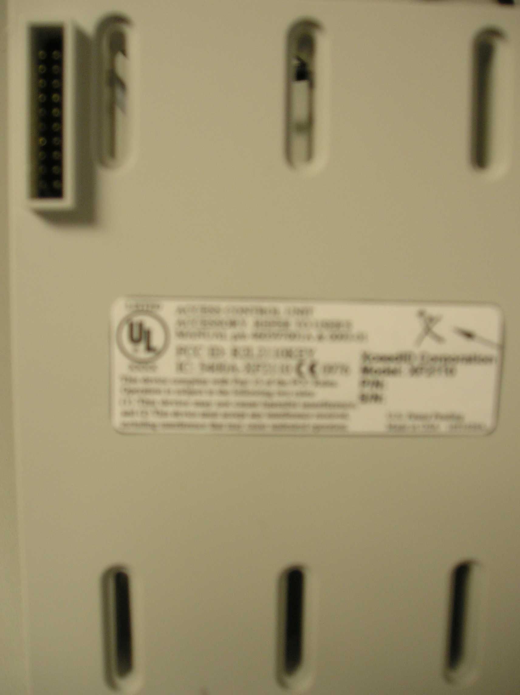
Document Text
Text extracted from the exhibit documents filed with the FCC. Open a document above to read the original.
Users Manual
XceedID : Document No: 0093-01; Issue No. 1; 10/18/04 INSTALLATION SHEET XF1100, XF2100, XF2110 PARTS LIST: • 1 - Installation Sheet • 1 - Reader • 2 - Mounting Screws • 1 - Security Screw (2 w/XF2100 and XF2110) Removal: 1. Remove unit from box. 2. Notice the connector on the inside of the cover plastic and the base unit plastic. The connector will end up at the top side of the reader when mounted. (ILLUSTRATION) Mounting the Reader: 1. Determine an appropriate mounting position on the door frame or wall, be sure to account for any applicable ADA height requirements. 2. Drill a minimum of two mounting holes a minimum of 3.2” apart on the mounting surface of the door frame or wall. Drill one 3/4” diameter cable hole for the pigtail wire connection. Wire the unit according to the color code chart below. Screw base unit to wall. (ILLUSTRATION) 3. Following cable connection (see the cable connection diagram below), re-install the plastic cover to the reader base. The base male connectors should align with the cover connector holes and the bottom slot should easily slide over and snap into place over the plastic dimple of the base. After ensuring connection, install the security screw on the bottom of the reader. Cable Connections: 1. XceedID readers are supplied with a 12 conductor cable pigtail. Connect this pigtail with the host/panel being careful to match the color of each wire with the chart shown below. (ILLUSTRATION) Yellow = Beeper Blue = Hold Purple = Open Collector/Card present Green = Data 0 White = Data 1 Orange = Green LED Brown = Red LED Red = Power +DC (6-16 VDC) Black = Ground Pink = RQE (Request to Exit input) Grey = DI (Door DI Input) Tan = Tamper Output Drain = Shield Ground XceedID : Document No: 0093-01; Issue No. 1; 10/18/04 2. Use a linear DC power source between 6 volts and 16 volts. 3. Be sure the reader is properly grounded by attaching the ground wire to an earth ground connection at the power supply or panel end of the cable. Testing the Reader: 1. Power up the reader. The LED will light followed by a beeper tone. This indicates that the reader is ready. 2. Present a proper card or token programmed to operate the reader and a green LED flash will indicate successful operation. Note that a red flash could simply indicate an incorrect match or mis-programmed card/token rather than a faulty reader installation . Additional Notes: • The voltage specification for these products is 6 volts to 16 volts. Higher voltage within these specifications will result in better performance. • Typical cable guage ranges from 18 to 22 guage. Check with your cable supplier to determine the best choice for your application and installation distance . Specifications: • Power Supply: Linear DC • Voltage Range: 6 – 16VDC • Temperature Range: -25F to 125F • Card Read Distance: Up to 4.5” – Distance can vary widely depending on installation conditions and credential type. • Cable Distance to Panel in Wiegand mode: o 500 ft. maximum at 12 volts o 200 ft. maximum at 6 volts • Information Output: Wiegand = 64 bits; RS485 = 128k bits per second • Tamper Output: Open Collector • Regulatory Approvals and Standards UL ISO15693 ISO14443A Europe: CE Listed. Federal Communications Statement: The FCC requires the following statement for your information: This reader utilizes and radio frequency energy and has been tested and complies with the limits of FCC testing. Changes, modifications or disregard of proper installation instructions not expressly approved by XceedID Corporation is strictly prohibited by the FCC and could void the user’s authority to operate the equipment. For Canadian Users: This unit has been tested and meets all applicable Industry of Canada technical specifications. • This device may not cause radio frequency interference. • This device must accept radio frequency interference. In the unlikely event interference occurs, please contact the manufacturer. XceedID : Document No: 0093-01; Issue No. 1; 10/18/04
Users Manual
XceedID : Document No: 0093-01; Issue No. 1; 10/18/04 INSTALLATION SHEET XF1100, XF2100, XF2110 PARTS LIST: • 1 - Installation Sheet • 1 - Reader • 2 - Mounting Screws • 1 - Security Screw (2 w/XF2100 and XF2110) Removal: 1. Remove unit from box. 2. Notice the connector on the inside of the cover plastic and the base unit plastic. The connector will end up at the top side of the reader when mounted. (ILLUSTRATION) Mounting the Reader: 1. Determine an appropriate mounting position on the door frame or wall, be sure to account for any applicable ADA height requirements. 2. Drill a minimum of two mounting holes a minimum of 3.2” apart on the mounting surface of the door frame or wall. Drill one 3/4” diameter cable hole for the pigtail wire connection. Wire the unit according to the color code chart below. Screw base unit to wall. (ILLUSTRATION) 3. Following cable connection (see the cable connection diagram below), re-install the plastic cover to the reader base. The base male connectors should align with the cover connector holes and the bottom slot should easily slide over and snap into place over the plastic dimple of the base. After ensuring connection, install the security screw on the bottom of the reader. Cable Connections: 1. XceedID readers are supplied with a 12 conductor cable pigtail. Connect this pigtail with the host/panel being careful to match the color of each wire with the chart shown below. (ILLUSTRATION) Yellow = Beeper Blue = Hold Purple = Open Collector/Card present Green = Data 0 White = Data 1 Orange = Green LED Brown = Red LED Red = Power +DC (6-16 VDC) Black = Ground Pink = RQE (Request to Exit input) Grey = DI (Door DI Input) Tan = Tamper Output Drain = Shield Ground XceedID : Document No: 0093-01; Issue No. 1; 10/18/04 2. Use a linear DC power source between 6 volts and 16 volts. 3. Be sure the reader is properly grounded by attaching the ground wire to an earth ground connection at the power supply or panel end of the cable. Testing the Reader: 1. Power up the reader. The LED will light followed by a beeper tone. This indicates that the reader is ready. 2. Present a proper card or token programmed to operate the reader and a green LED flash will indicate successful operation. Note that a red flash could simply indicate an incorrect match or mis-programmed card/token rather than a faulty reader installation . Additional Notes: • The voltage specification for these products is 6 volts to 16 volts. Higher voltage within these specifications will result in better performance. • Typical cable guage ranges from 18 to 22 guage. Check with your cable supplier to determine the best choice for your application and installation distance . Specifications: • Power Supply: Linear DC • Voltage Range: 6 – 16VDC • Temperature Range: -25F to 125F • Card Read Distance: Up to 4.5” – Distance can vary widely depending on installation conditions and credential type. • Cable Distance to Panel in Wiegand mode: o 500 ft. maximum at 12 volts o 200 ft. maximum at 6 volts • Information Output: Wiegand = 64 bits; RS485 = 128k bits per second • Tamper Output: Open Collector • Regulatory Approvals and Standards UL ISO15693 ISO14443A Europe: CE Listed. Federal Communications Statement: The FCC requires the following statement for your information: This reader utilizes and radio frequency energy and has been tested and complies with the limits of FCC testing. Changes, modifications or disregard of proper installation instructions not expressly approved by XceedID Corporation is strictly prohibited by the FCC and could void the user’s authority to operate the equipment. For Canadian Users: This unit has been tested and meets all applicable Industry of Canada technical specifications. • This device may not cause radio frequency interference. • This device must accept radio frequency interference. In the unlikely event interference occurs, please contact the manufacturer. XceedID : Document No: 0093-01; Issue No. 1; 10/18/04
Cover Letter(s)
Response to E04-000099-1 1. The 731 form should have listed two separate specifications for the 125 kHz and 13.56 MHz parts. Please correct it for me. 2. The equipment code for the 13.56 MHz product should be DXT. 3. Label placement has been uploaded. 4. The customer says the users manual does not mention parts 11, 15 or 18, but the manual has been re-uploaded.
Cover Letter(s)
Revised Response to E04-000099-1 IC 1. At the time the report was written, Xceed ID was listed as the manufacturer by the customer. By the time submittal information was received, I was informed that the manufacturer was changed.
External Photos
Base Front Base Back Base Top Base Bottom Base Left Side Base Right Side 2110 Front 2110 Back 2110 Top 2110 Bottom 2110 Left Side 2110 Right Side
Internal Photos
Base Inside Base Front PCB Base Front PCB Close-up 1 Base Front PCB Close-up 2 Base Front PCB Close-up 3 Base Front PCB Close-up 4 Base Back PCB Base Back PCB Close-up 1 Base Back PCB Close-up 2 Base Back PCB Close-up 3 21xx Inside 21xx Front Antenna PCB 21xx Front Antenna PCB Close-up 1 21xx Front Antenna PCB Close-up 2 21xx Front Antenna PCB Close-up 3
Test Report
Page 1 of 36 Report No.: FC04-064 XCEEDID TEST REPORT FOR THE PHYSICAL ACCESS CONTROL READER, XF2110 FCC PART 15 SUBPART C SECTIONS 15.207, 15.209, 15.225 AND RSS-210 COMPLIANCE DATE OF ISSUE: AUGUST 31, 2004 PREPARED FOR: XceedID 112 N. Rubey Drive, Suite 100 Golden, CO 80403 PREPARED BY: Mary Ellen Clayton CKC Laboratories, Inc. 5473A Clouds Rest Mariposa, CA 95338 P.O. No.: 081604JDM W.O. No.: 82526 Date of test: August 18-26, 2004 Report No.: FC04-064 This report contains a total of 36 pages and may be reproduced in full only. Partial reproduction may only be done with the written consent of CKC Laboratories, Inc. The results in this report apply only to the items tested, as identified herein. Page 2 of 36 Report No.: FC04-064 TABLE OF CONTENTS Administrative Information .............................................................................................3 Summary of Results .........................................................................................................4 Conditions for Compliance ..............................................................................................4 Approvals .........................................................................................................................4 FCC 15.33(a) Frequency Ranges Tested .........................................................................5 FCC 15.35 Analyzer Bandwidth Settings ........................................................................5 FCC 15.203 Antenna Requirements ................................................................................5 FCC 15.205 Restricted Bands..........................................................................................5 Eut Operating Frequency .................................................................................................5 Temperature And Humidity During Testing....................................................................5 Equipment Under Test (EUT) Description ......................................................................6 Equipment Under Test .....................................................................................................6 Peripheral Devices ...........................................................................................................6 Report of Measurements ..................................................................................................7 Table 1: FCC 15.207 Six Highest Conducted Emission Levels ..........................7 Table 2: FCC 15.209 Fundamental Emission Levels: 125 kHz...........................7 Table 3: FCC 15.209 Six Highest Radiated Emission Levels: 9 kHz - 30 MHz .7 Table 4: FCC 15.209 Six Highest Radiated Emission Levels: 30-1000 MHz.....7 Table 5: FCC 15.225(a) Fundamental Emission Levels: 13.56 MHz..................7 FCC 15.225(a) Emissions Mask ..........................................................................7 FCC 15.225(c) Frequency Tolerance...................................................................7 RSS-210 20dB Bandwidth - 125 kHz ..................................................................7 RSS-210 20dB Bandwidth - 13.56 MHz .............................................................7 EUT Setup........................................................................................................................7 Correction Factors............................................................................................................7 Table A: Sample Calculations .............................................................................7 Test Instrumentation and Analyzer Settings ....................................................................7 Spectrum Analyzer Detector Functions ...............................................................7 Peak..........................................................................................................7 Quasi-Peak ...............................................................................................7 Average ....................................................................................................7 EUT Testing.....................................................................................................................7 Mains Conducted Emissions................................................................................7 Radiated Emissions ..............................................................................................7 Appendix A: Test Setup Photographs and Diagram ........................................................7 Photograph Showing Mains Conducted Emissions .............................................7 Photograph Showing Radiated Emissions ...........................................................7 Photograph Showing Radiated Emissions ...........................................................7 Diagram Showing Temperature Testing ..............................................................7 Appendix B: Test Equipment List ...................................................................................7 Appendix C: Measurement Data Sheets ..........................................................................7 Page 3 of 36 Report No.: FC04-064 ADMINISTRATIVE INFORMATION DATE OF TEST: August 18-26, 2004 DATE OF RECEIPT: August 18, 2004 PURPOSE OF TEST: To demonstrate the compliance of the Physical Access Control Reader, XF2110 with the requirements for FCC Part 15 Subpart C Sections 15.207, 15.209, 15.225 and RSS-210 devices. TEST METHOD: ANSI C63.4 (2001) MANUFACTURER: XceedID 112 N. Rubey Drive, Suite 100 Golden, CO 80403 REPRESENTATIVE: John Menzel TEST LOCATION: CKC Laboratories, Inc. 5473A Clouds Rest Mariposa, CA 95338 Page 4 of 36 Report No.: FC04-064 SUMMARY OF RESULTS As received, the XceedID Physical Access Control Reader, XF2110 was found to be fully compliant with the following standards and specifications: Canadian Standard Canadian Section FCC Stan…
Text truncated - open the document above for the full version.
Test Setup Photos
PHOTOGRAPH SHOWING MAINS CONDUCTED EMISSIONS Mains Conducted Emissions - Front View PHOTOGRAPH SHOWING RADIATED EMISSIONS Radiated Emissions - Front View PHOTOGRAPH SHOWING RADIATED EMISSIONS Radiated Emissions - Back View
Contact Information
Applicant
Dan Munson(Senior Electronics Engineering Manager)
Technical Contact
CKC Laboratories, Inc.Mary Ellen Clayton
[email protected]800-500-4362
5473-A Clouds Rest · Mariposa, California · United States
Test Firm
CKC Laboratories, Inc.Steve Behm
Technical Specifications
| # | Rule Parts | Frequency Range | Power Output |
|---|---|---|---|
| 2 | 15C | 13.56 MHz - 13.56 MHz | - |
Other Applications from XceedID Corporation

R2LMT20W
Oct 06, 2015The MT20w is a Credential Enrollment Reader for access control systems.
Equipment Class
DCD - Part 15 Low Power Transmitter Below 1705 kHz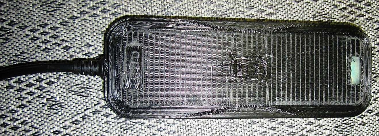
R2LMT20
Nov 20, 2014The MT20 is a Credential Enrollment Reader for access control systems.
Equipment Class
DXX - Part 15 Low Power Communication Device Transmitter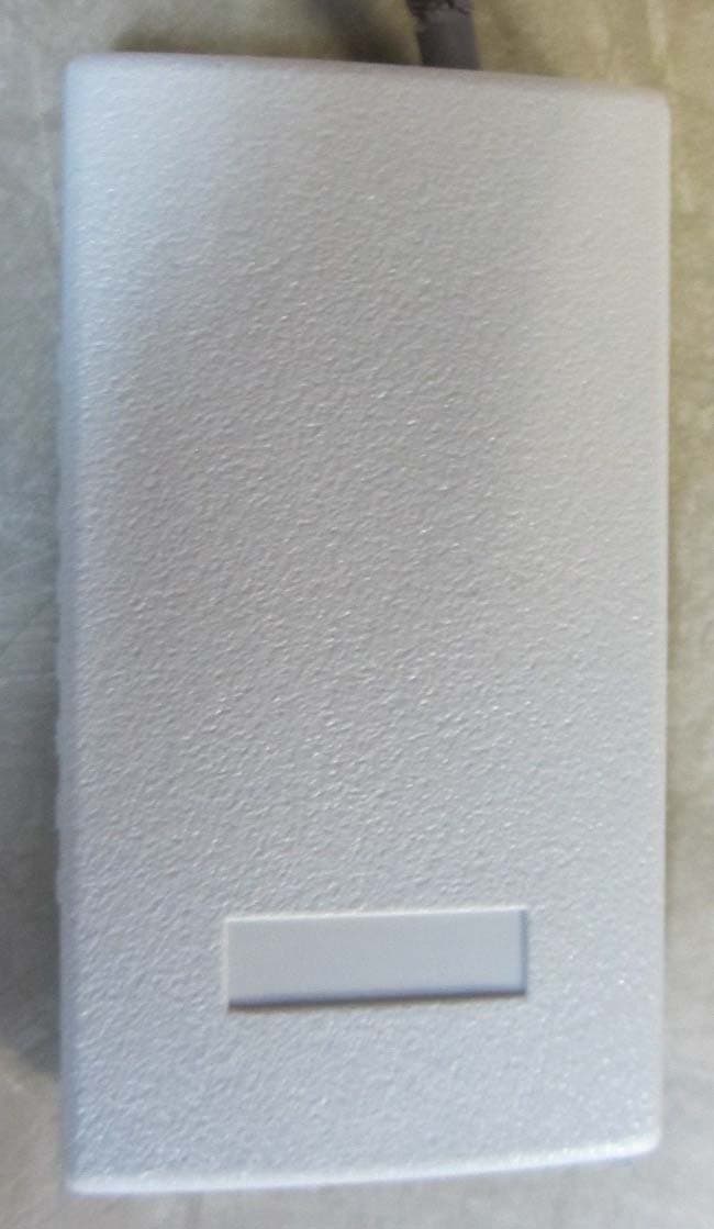
R2LSSU89
Jul 12, 2012Credential Access Reader
Equipment Class
DXT - Part 15 Low Power Transceiver, Rx Verified
R2LMT11-485
Jun 11, 2012Access Control Reader
Equipment Class
DCD - Part 15 Low Power Transmitter Below 1705 kHz
R2LMTK15-485
Jun 11, 2012Access Control Reader
Equipment Class
DXT - Part 15 Low Power Transceiver, Rx Verified