R2LSM10Access Control Reader
XceedID Corporation
Click to zoom
Application Details
- Equipment Class
- DXT - Part 15 Low Power Transceiver, Rx Verified
- Date of Grant
- Jun 11, 2012
- Application Purpose
- Original Equipment
- Date of Application
- Jun 06, 2012
- Equipment Note
- Access Control Reader
- Frequency Range
- 13.56000000 - 13.56000000
- Company
- XceedID Corporation
- Country
- United States
Documents & Files
Document Text
Text extracted from the exhibit documents filed with the FCC. Open a document above to read the original.
Users Manual
Support and Warranty Soporte y garantía www.schlage.com/support www.schlage.com/support (877) 671-7011 (877) 671-7011 23923329 FCC Statement This device complies with part 15 of the FCC rules. Operation is subject to the following two conditions: (1) This device may not cause harmful interference, and (2) this device must accept any interference received, including interference that may cause undesired operation. Changes or modifi cations to this equipment not expressly approved by Ingersoll Rand could void the user’s authority to operate the equipment. Industry Canada Statement: This device complies with Industry Canada licence-exempt RSS standard(s). Operation is subject to the following two conditions: (1) this device may not cause interference, and (2) this device must accept any interference, including interference that may cause undesired operation of the device. Declaraciones de la FCC Este dispositivo cumple con la Sección 15 de las normas de la CCF .La utilización está sujeta a las siguientes dos condiciones: (1) Este dispositivo no puede causar interferencia dañina y (2) este dispositivo debe aceptar cualquier interferencia recibida, incluyendo interferencia que pueda causar un funcionamiento indeseado. Los cambios o modifi caciones a este equipo sin autorización expresa de Schlage podrían anular la autoridad del usuario para utilizar el equipo. Declaraciones de Industry Canada Este dispositivo cumple con los estándares RSS de licencia exenta de Industry Canada. Su utilización está sujeta a las siguientes dos condiciones: (1) este dispositivo no puede causar interferencia y (2) este dispositivo debe aceptar cualquier interferencia, incluyendo interferencia que pueda causar un funcionamiento no deseado. 1 Separate case from baseplate. Separe la carcasa de la placa base. 2 Mark and drill holes. NOTE: Drill and tap for mounting on metal surface. Use ¹⁄₈" (3 mm) holes for mounting on wood, or appropriate anchors for other surfaces. Marque y perfore orifi cios. NOTA: Para el montaje, perfore orifi cios sobre una superfi cie metálica y hágales rosca. Utilice orifi cios de ¹⁄₈" (3 mm) para montar sobre madera, o bien anclajes adecuados para otras superfi cies. Baseplate Placa base Case Carcasa Drill and tap 6-32 hole Perfore un orifi co de 6-32 y hágale rosca Drill and tap 6-32 hole Perfore un orifi co de 6-32 y hágale rosca 1" (25 mm) 4 Route cable through holes.Pase el cable a través de los orifi cios. 5 Install baseplate. Instale la placa base. 6 Plug cable into case.Enchufe el cable en la carcasa. 7 Install case.Instale la carcasa. 8 Snap cover into place and install cover screw. Coloque la cubierta en su lugar e instale el tornillo de la cubierta. TESTPRUEBA a Power the reader. The LED will light followed by a beeper tone. This indicates that the reader is ready. If LED and beeper do not respond, check cable connections. Encienda el lector. Se encenderá el LED seguido de un tono de alerta sonora. Eso indica que el lector está preparado. Si el LED y la alerta sonora no responden, verifi que las conexiones de los cables. b Present a proper card or token programmed to operate the reader. Presente una tarjeta apropiada o una clave programada para operar el lector. LED IndicatorsIndicadores de LED GreenCard was read and accepted Verde Se leyó y aceptó la tarjeta RedCard was read but not accepted (does not indicate faulty installation) RojoSe leyó la tarjeta, pero no se aceptó (no indica que haya una instalación defectuosa) Tamper Resistant Resistente a la manipulación 6-32 x ¹⁄₄" Pin-in-Torx button head Use if desired. Perno de cabeza semiesférica Pin-in- Torx de 6-32 x ¹⁄₄" Utilícelo si lo desea. Regular 6-32 x ¹⁄₄" Regular 6-32 x ¹⁄₄" Do not over-tighten! ¡No apriete demasiado! 3 Wire the cable to the control module. A UL 294 approved power supply must be used. Voltage rating: 5V to 16V Conecte el cable al módulo de control. Se debe utilizar un suministro de energía aprobado por UL 294. Rango de tensión: 5 V a 16 V Max. Length to PanelLong. máx. al panel LengthAWGLongitud AWG 200' 22 60 m 22 300' 20 90 m 20 500' 18 150 m 18 Current @ 12V and 25CCorriente a 12 V y 25 C ModelAvg. mAMax. mAModelo Promedio de mA Máximo de mA PR10 65 110 PR10 65 110 SPR10SPR10 BPR10BPR10 SM10 90 170 SM10 90 170 SSM10SSM10 BSM10BSM10 MT11 125140 MT11 125140 SMT11SMT11 BMT11BMT11 Cable ConnectionsConexiones de cables Black Ground Negro Tierra BlueUnusedAzulSin uso BrownRed LED ControlMarrónControl de LED rojo GrayTamper OutGrisManipulación Green Wiegand Data 0 / DataVerdeDatos Wiegand 0 / Datos OrangeGreen LED Control AnaranjadoControl de LED verde Pink*RS485-A/YRosa*RS485-A/Y RedPower InRojoEncendido ShieldShield GroundBlindadoDescarga del blindaje Tan*RS485-B/ZHabano*RS485-B/Z White Wiegand Data 1 / ClockBlancoDatos Wiegand 1 / Reloj Yellow Beeper ControlAmarillo Control de alerta sonora * These wires are unused for readers that do not support RS485 communication. * Estos cables no se utilizan para lectores que no admiten la comunicación RS485. Tools • Phillips Screwdriver • 6-32 Tap • 1" (25 mm), ¹⁄₈" (3 mm) Drill Bits • T10 Security Torx™ Bit (Optional) Herramientas • Desatornillador Phillips • Macho de roscar de 6-32 • Brocas de 1" (25 mm), ¹⁄₈" (3 mm) • Mecha T10 Security Torx™ (Opcional) MULLION READERS INSTALLATION INSTRUCTIONS MODELS PR10, SPR10, BPR10, SM10, SSM10, BSM10, MT11, SMT11, BMT11 LECTORES MULLION INSTRUCCIONES DE INSTALACIÓN MODELOS PR10, SPR10, BPR10, SM10, SSM10, BSM10, MT11, SMT11, BMT11 PR10 SPR10 BPR10 Proximity Reader— Mini-Mullion Lector de proximidad— Minimontante SM10 SSM10 BSM10 Smart Reader— Mini-Mullion Lector inteligente— Minimontante MT11 SMT11 BMT11 Multi-Technology Reader— Mullion Lector multitecnología— Montante Soutien et garantie Suporte e garantia www.schlage.com/support www.ingersollrand.com.br/seguranca (877) 671-7011 0800 774 8080 © 2012 Ingersoll Rand Printed in U.S.A. 23923329 02/12-a Énoncés FCC Cet appareil est conforme à la partie 15 des normes FC…
Text truncated - open the document above for the full version.
ID Label/Location Info
Title Number Revision Created By Creation Date EC Number Revision Description: Schlage Lock Company Copyright © 2012 Material Edited ByApproved ByRelease Date Revision History A BCDEF Notes Software: Illustrator CS4 Activity 3899 Hancock Expwy Security, CO 80911 EC#EC #EC #EC #EC #EC # A> New Item 021968 05-29-12 D Salvetti B Massey Label, UL, Ithaca, SM10 D Salvetti 09-16-11 23959844 A 1. Tolerance: ±0.03 2. Style: D/C, Pressure sensitive 3. Dimensions: 1.9” wide x 0.6” tall 4. Printing: Thermal transfer 5. Format: Roll 6. Make from blank label 23965726 See speci cation for blank label listed below 1.9” Graphics shown at 2:1 scale 0.6” 1.9” 0.6” SEE INSTALL INSTRUCTIONS 23923329 FCC ID: R2LSM10 IC: 5400A-SM10 XceedID Corporation MODEL: SM10 Suitable for Outdoor Use U.S. Patent 7676839 0976 ! EQUIPMENT Access Control System Reader 22DV LISTED LISTED Actual Size XXXXXXXXXXXXX XXXXXXXXXX SNXXXXXXXX ORIGIN: US YYMMDDX SOXXXXXXXXXX Content Description of Variable Fields Line 1: 13 characters to identify rmware version Line 2: 10 characters to identify product con guration Line 3: 10 characters to identify sales order # (including “SO”) Line 4: 10 Characters to identify serial # (including “SN”) Line 5: Date and Station Number (YYMMDDX) Line 6: 10 characters to identify Country of Origin - “ORIGIN: US” SEE INSTALL INSTRUCTIONS 23923329 FCC ID: R2LSM10 IC: 5400A-SM10 XceedID Corporation MODEL: SM10 Suitable for Outdoor Use U.S. Patent 7676839 0976 ! EQUIPMENT Access Control System Reader 22DV LISTED LISTED XXXXXXXXXXXXX XXXXXXXXXX SNXXXXXXXX ORIGIN: US YYMMDDX SOXXXXXXXXXX
Test Report
This report contains a total of 31 pages and may be reproduced in full only. Partial reproduction may only be done with the written consent of CKC Laboratories, Inc. Ingersoll Rand ADDENDUM TEST REPORT TO 92314-10 Smart Reader, SM10 Tested To The Following Standards: FCC Part 15 Subpart C Sections 15.207, 15.225 and RSS 210 Issue 8 Report No.: 92314-10A Date of issue: June 6, 2012 This test report bears the accreditation symbol indicating that the testing performed herein meets the test and reporting requirements of ISO/IEC 17025 under the applicable scope of EMC testing for CKC Laboratories, Inc. We strive to create long-term, trust based relationships by providing sound, adaptive, customer first testing services. We embrace each of our customers’ unique EMC challenges, not as an interruption to set processes, but rather as the reason we are in business. Page 2 of 31 Report No.: 92314-10A TABLE OF CONTENTS Administrative Information .......................................................................................................................... 3 Test Report Information ............................................................................................................................................ 3 Revision History ......................................................................................................................................................... 3 Report Authorization ................................................................................................................................................. 3 Test Facility Information ............................................................................................................................................ 4 Site Registration & Accreditation Information .......................................................................................................... 4 Summary of Results ................................................................................................................................................... 5 Conditions During Testing.......................................................................................................................................... 5 Equipment Under Test ............................................................................................................................................... 6 Peripheral Devices ..................................................................................................................................................... 6 FCC Part 15 Subpart C ................................................................................................................................... 7 15.207 Conducted Emissions ..................................................................................................................................... 7 15.225(a)(b)(c)(d) Carrier and Spurious Emissions .................................................................................................. 14 Carrier Radiated Emissions .................................................................................................................................. 14 Spurious Radiated Emissions ............................................................................................................................... 18 Frequency Stability .................................................................................................................................................. 24 RSS-210 ....................................................................................................................................................... 27 99 % Bandwidth ....................................................................................................................................................... 27 Supplemental Information .......................................................................................................................... 30 Measurement Uncertainty ...................................................................................................................................... 30 Emissions Test Details .............................................................................................................................................. 30 Page 3 of 31 Report No.: 92314-10A ADMINISTRATIVE INFORMATION Test Report Information REPORT PREPARED FOR: REPORT PREPARED BY: Ingersoll Rand 500 Golden Ridge Road Bldg. 1, Suite 160 Golden, CO 80401 Joyce Walker CKC Laboratories, Inc. 5046 Sierra Pines Drive Mariposa, CA 95338 Representative: Bryan Hoff Project Number: 92314 Customer Reference Number: 4011258 DATE OF EQUIPMENT RECEIPT: March 12, 2012 DATE(S) OF TESTING: March 12-April 3, 2012 Revision History Original: Testing of the Smart Reader, SM10 to FCC Part 15 Subpart C Sections 15.207, 15.225 and RSS 210 Issue 8. Addendum A: Replaced the 15.225 Carrier data sheet with corrected data, which also added a statement regarding 15.31(e) testing and revised the frequency stability table. Updated test conditions for 15.207 testing. Report Authorization The test data contained in this report documents the observed testing parameters pertaining to and are relevant for only the sample equipment tested in the agreed upon operational mode(s) and configuration(s) as identified herein. Compliance assessment remains the client’s responsibility. This report may not be used to claim product endorsement by A2LA or any government agencies. This test report has been authorized for release under quality control from CKC Laboratories, Inc. Steve Behm Director of Quality Assurance & Engineering Services CKC Laboratories, Inc. Page 4 of 31 Report No.: 92314-10A Test Facility Information Our laboratories are configured to effectively test a wide variety of product types. CKC utilizes first class test equipment, anechoic chambers, data acquisition and information services to create acc…
Text truncated - open the document above for the full version.
Contact Information
Applicant
Dan Munson(Senior Electronics Engineering Manager)
Technical Contact
XceedID CorporationBryan Hoff
[email protected]3036403679
500 Golden Ridge Rd. · Golden, Colorado · United States
Test Firm
CKC Laboratories, Inc.Steve Behm
Technical Specifications
| # | Rule Parts | Frequency Range | Power Output |
|---|---|---|---|
| 1 | 15C | 13.56 MHz - 13.56 MHz | - |
Other Applications from XceedID Corporation

R2LMT20W
Oct 06, 2015The MT20w is a Credential Enrollment Reader for access control systems.
Equipment Class
DCD - Part 15 Low Power Transmitter Below 1705 kHz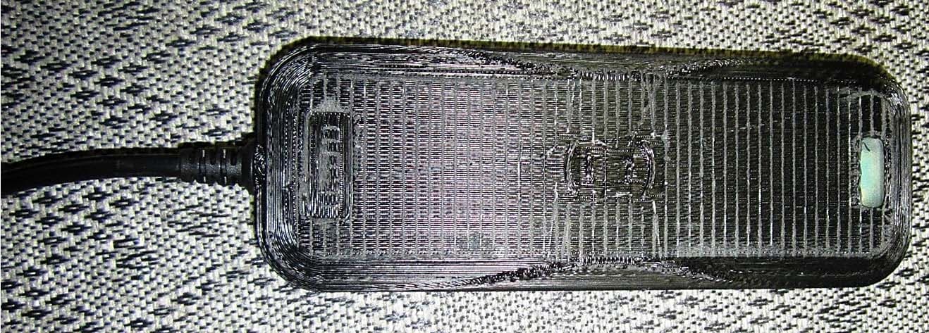
R2LMT20
Nov 20, 2014The MT20 is a Credential Enrollment Reader for access control systems.
Equipment Class
DXX - Part 15 Low Power Communication Device Transmitter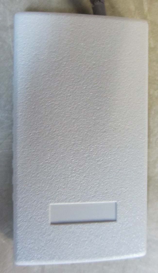
R2LSSU89
Jul 12, 2012Credential Access Reader
Equipment Class
DXT - Part 15 Low Power Transceiver, Rx Verified
R2LMT11-485
Jun 11, 2012Access Control Reader
Equipment Class
DCD - Part 15 Low Power Transmitter Below 1705 kHz
R2LMTK15-485
Jun 11, 2012Access Control Reader
Equipment Class
DXT - Part 15 Low Power Transceiver, Rx Verified