R2LXF1560WMTAccess Control Reader: Smart Card
XceedID Corporation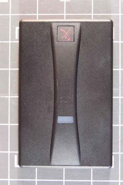
Click to zoom
Application Details
- Equipment Class
- DXX - Part 15 Low Power Communication Device Transmitter
- Date of Grant
- Apr 29, 2007
- Application Purpose
- Original Equipment
- Date of Application
- Apr 16, 2007
- Equipment Note
- Access Control Reader: Smart Card
- Frequency Range
- 13.56000000 - 13.56000000
- Company
- XceedID Corporation
- Country
- United States
Documents & Files
Document Text
Text extracted from the exhibit documents filed with the FCC. Open a document above to read the original.
Users Manual
XceedID : Document No: 0405-01; Issue No. 1; 3/30/2007 INSTALLATION SHEET XF1500/XF1560 PARTS LIST: • 1 - Installation Sheet • 1 - Mounting Plate • 1 - Potted Reader Assembly • 1 - Cover • 2 - Mounting Screws • 1 – Cover Assembly Screw Removal: 1. Remove unit from box. Mounting the Reader: 1. Determine an appropriate mounting position on a single gang box or wall. Be sure to account for any applicable ADA height requirements. 2. For a single gang box mount, attach the back-plate to the holes in the single gang box using the screws provided. 3. For a wall mount, drill two mounting holes between 2.5” and 3.5” apart on the mounting surface. Drill one 3/4” diameter cable hole for the pigtail wire connection. 4. Connect the mounting plate to the wall using the screws provided. 5. Wire the unit according to the color code chart below ensuring that all connections are made through the center hole in the mounting plate. 6. Hook the top of the potted case assembly to the top of the mounting plate. 7. Swivel the unit down into place and snap the cover over the potted reader assembly. 8. Install the screw from the bottom to fix the cover to the potted case to the mounting plate. Cable Connections: 1. XceedID XF1500/XF1560 readers are supplied with a 12 conductor cable pigtail. Connect this pigtail with the host/panel being careful to match the color of each wire with the chart shown below. Green = Data 0 White = Data 1 Orange = Green LED Brown = Red LED Red = Power +DC (5-16 VDC) Black = Ground Tan = Tamper Output Pink = Card Present Yellow = Beeper Gray = Not Used Purple = Not Used Blue = Not Used 2. Use a DC power source between 5 volts and 16 volts. XceedID : Document No: 0405-01; Issue No. 1; 3/30/2007 3. Be sure the reader is properly grounded by attaching the ground wire to an earth ground connection at the power supply or panel end of the cable. Testing the Reader: 1. Power up the reader. The LED will light followed by a beeper tone. This indicates that the reader is ready. 2. Present a proper card or token programmed to operate the reader and a green LED flash will indicate successful operation. Note that a red flash could simply indicate an incorrect match or miss-programmed card/token rather than a faulty reader installation. Additional Notes: • The voltage specification for these products is 5 volts to 16 volts. • Typical cable gauge ranges from 18 to 22 gauge. Check with your cable supplier to determine the best choice for your application and installation distance . Specifications: • Power Supply: DC • Voltage Range: 5 – 16VDC • Temperature Range: -31F to 149F • Card Read Distance: Up to 4.5” – Distance can vary widely depending on installation conditions and credential type. • Cable Distance to Panel in Wiegand mode: o 500 ft. maximum @ 22 awg for 12 volt supply. o 200 ft. maximum @ 22 awg for 5 volt supply. • Information Output: Wiegand • Regulatory Approvals and Standards UL 294 ISO15693 ISO14443A Europe: CE Listed. Federal Communications Statement: The FCC requires the following statement for your information: This device complies with Part 15 of the FCC Rules. Operation is subject to the following two conditions: (1) this device may not cause harmful interference, and (2) this device must accept any interference received, including interference that may cause undesired operation. This reader utilizes and radio frequency energy and has been tested and complies with the limits of FCC testing. Changes, modifications or disregard of proper installation instructions not expressly approved by XceedID Corporation is strictly prohibited by the FCC and could void the user’s authority to operate the equipment. For Canadian Users: This unit has been tested and meets all applicable Industry of Canada technical specifications. • This device may not cause radio frequency interference. • This device must accept radio frequency interference. In the unlikely event interference occurs, please contact the manufacturer.
Cover Letter(s)
112 North Rubey Drive, Suite 100, Golden, CO 80403 Tel: 303-273-9930 Fax: 303-273-9937 Federal Communications Commission 7435 Oakland Mills Road Columbia, MD 21046 4/11/2007 Gentlemen: This letter is to comply with Section 0.457(d)(2)(i) pertaining to confidential material. XceedID Corporation would like the documents regarding schematics, block diagrams and operational descriptions for this submission for FCC ID: R2L1560WMT to be kept confidential. The information submitted provides XceedID a competitive advantage in the market. The submitted material also contains trade secrets or technical data, which would customarily be guarded from competitors. We do NOT want these documents to be accessible to the general public. Sincerely, Michael T. Conlin VP Engineering XceedID Corporation
Cover Letter(s)
Read Me First – WO 85643 Model XF1560 This is a new submittal for both the US and Canada. The exhibits have been put in the TCB folder. Testing was performed by Randy and Mike. The Canadian application form has been uploaded but is not yet complete. Also, a draft of the test report has been uploaded, but not yet approved by the customer.
External Photos
All Models - External Front XF15xxP models - External Back XF15xxP models - External Back Potted XF15xxC models - External Back XF15xxC models - External Back Potted All Models - Top All Models - Bottom All Models - Left Side All Models - Right Side
ID Label/Location Info
11 22 33 44 A A B B TITLE SIZE DWG NO REV SCALE SHEET OF DRAWNCHECKED QA MFG APPROVED LABEL, WALLMOUNT XF 1560 READERPRODUCT 0457-01 1 1 A B XCEEDID PROPRIETARY AND CONFIDENTIAL Mike Conlin 4/10/2007 3.00 2.00 R0.13 3.00 2.00 3.00 2.00 3.00 2.00 R0.13 R0.13 R0.13
Internal Photos
XF 1560 – Antenna Load XF1560CS2 - Enclosure XF1560CS2 – PCB Front XF1560CS2 – PCB Back XF1560CS4 - Enclosure XF1560CS4 – PCB Front XF1560CS4 – PCB Back XF1560PS2 - Enclosure XF1560PS2 – PCB Front XF1560PS2 – PCB Back
Test Report
Page 1 of 47 Report No.: FC07-018 XCEEDID TEST REPORT FOR THE SMART CARD READER, XF1560CS2, XF1560CS4 & XF1560PS2 FCC PART 15 SUBPART C SECTIONS 15.207, 15.209 & 15.225 AND SUBPART B SECTIONS 15.107 & 15.109 CLASS B COMPLIANCE DATE OF ISSUE: MARCH 21, 2007 PREPARED FOR: XceedID 112 N. Rubey Drive, Suite 100 Golden, CO 80403 PREPARED BY: Mary Ellen Clayton CKC Laboratories, Inc. 5046 Sierra Pines Drive Mariposa, CA 95338 P.O. No.: MC012607-1 W.O. No.: 85643 Date of test: January 15 - March 15, 2007 Report No.: FC07-018 This report contains a total of 47 pages and may be reproduced in full only. Partial reproduction may only be done with the written consent of CKC Laboratories, Inc. The results in this report apply only to the items tested, as identified herein. Page 2 of 47 Report No.: FC07-018 TABLE OF CONTENTS Administrative Information .............................................................................................3 Approvals .........................................................................................................................3 FCC to Canada Standard Correlation Matrix...................................................................4 Conditions for Compliance ..............................................................................................4 FCC 15.33(a) Frequency Ranges Tested .........................................................................5 FCC 15.35 Analyzer Bandwidth Settings ........................................................................5 FCC 15.203 Antenna Requirements ................................................................................5 EUT Operating Frequency ...............................................................................................5 Temperature And Humidity During Testing....................................................................5 Equipment Under Test (EUT) Description ......................................................................6 Equipment Under Test .....................................................................................................6 Peripheral Devices ...........................................................................................................6 Report of Emissions Measurements.................................................................................7 Testing Parameters...............................................................................................7 FCC 15.109 Radiated Emissions .........................................................................9 FCC 15.107/15.207 Conducted Emissions ..........................................................13 FCC 15.209 Radiated Emissions .........................................................................26 FCC 15.225 Radiated Emissions .........................................................................36 Occupied Bandwidth............................................................................................40 Frequency Stability ..............................................................................................43 FCC 15.225/RSS-210 Emissions Masks .............................................................45 Page 3 of 47 Report No.: FC07-018 ADMINISTRATIVE INFORMATION DATE OF TEST: January 15 - March 15, 2007 DATE OF RECEIPT: January 15, 2007 MANUFACTURER: XceedID 112 N. Rubey Drive, Suite 100 Golden, CO 80403 REPRESENTATIVE: Mike Conlin TEST LOCATION: CKC Laboratories, Inc. 5046 Sierra Pines Drive Mariposa, CA 95338 TEST METHOD: ANSI C63.4 (2003) PURPOSE OF TEST: To demonstrate the compliance of the Smart Card Reader, XF1560CS2, XF1560CS4 & XF1560PS2 with the requirements for FCC Part 15 Subpart C Sections 15.207, 15.209 & 15.225 and Subpart B Sections 15.107 & 15.109 Class B devices. APPROVALS Steve Behm, Director of Engineering Services QUALITY ASSURANCE:TEST PERSONNEL: Joyce Walker, Quality Assurance Administrative Manager Mike Wilkinson, EMC Engineer/Lab Manager Randy Clark, EMC Engineer Page 4 of 47 Report No.: FC07-018 FCC TO CANADA STANDARD CORRELATION MATRIX Canadian Standard Canadian Section FCC StandardFCC SectionTest Description RSS GEN7.1.447CFR15.203Antenna Connector Requirements RSS GEN7.2.147CFR15.35(c)Pulsed Operation RSS GEN7.2.247CFR15.207AC Mains Conducted Emissions Requirement RSS 2102.147CFR15.215(c)Frequency Stability Recommendation RSS 2102.247CFR15.205Restricted Bands of Operation RSS 2102.647CFR15.209General Radiated Emissions Requirement RSS 210A2.647CFR15.225(a-c) Fundamental and Emissions Mask Requirements RSS 210A2.6NANA±150kHz to ±450kHz Emissions Requirement RSS 210A2.647CFR15.225(d)Out of band emissions RSS 210A2.647CFR15.225(e)Carrier Stability IC 3082A-1784962Site File No. CONDITIONS FOR COMPLIANCE No modifications to the EUT were necessary to comply. Page 5 of 47 Report No.: FC07-018 FCC 15.33(a) Frequency Ranges Tested 15.109 Radiated Emissions: 30 MHz – 1000 MHz 15.107/15.207 Conducted Emissions: 150 kHz – 30 MHz 15.209 Radiated Emissions: 9 kHz – 1000 MHz 15.225 Radiated Emissions: Carrier. FCC SECTION 15.35: ANALYZER BANDWIDTH SETTINGS PER FREQUENCY RANGE TESTBEGINNING FREQUENCYENDING FREQUENCYBANDWIDTH SETTING CONDUCTED EMISSIONS150 kHz30 MHz9 kHz RADIATED EMISSIONS9 kHz150 kHz200 Hz RADIATED EMISSIONS150 kHz30 MHz9 kHz RADIATED EMISSIONS30 MHz1000 MHz120 kHz RADIATED EMISSIONS1000 MHz40 GHz1 MHz FCC 15.203 Antenna Requirements The antenna is an integral part of the EUT and is non-removable; therefore the EUT complies with Section 15.203 of the FCC rules. EUT Operating Frequency The EUT was operating at 13.56 MHz. Temperature And Humidity During Testing The temperature during testing was within +15°C and + 35°C. The relative humidity was between 20% and 75%. Page 6 of 47 Report No.: FC07-018 EQUIPMENT UNDER TEST (EUT) DESCRIPTION The customer declares the EUT tested by CKC Laboratories was representative of a production unit. The following models have been tested by CKC Laboratories: Smart Card Rea…
Text truncated - open the document above for the full version.
Test Setup Photos
RADIATED EMISSIONS Test Setup Photos CONDUCTED EMISSIONS Test Setup Photos FREQUENCY STABILITY Test Setup Photos
Contact Information
Applicant
Dan Munson(Senior Electronics Engineering Manager)
Technical Contact
CKC Laboratories, Inc.Mary Ellen Clayton
[email protected]209-966-5240
5046 Sierra Pines Drive · Mariposa, California · United States
Test Firm
CKC Laboratories, Inc.Steve Behm
Technical Specifications
| # | Rule Parts | Frequency Range | Power Output |
|---|---|---|---|
| 1 | 15C | 13.56 MHz - 13.56 MHz | - |
Other Applications from XceedID Corporation

R2LMT20W
Oct 06, 2015The MT20w is a Credential Enrollment Reader for access control systems.
Equipment Class
DCD - Part 15 Low Power Transmitter Below 1705 kHz
R2LMT20
Nov 20, 2014The MT20 is a Credential Enrollment Reader for access control systems.
Equipment Class
DXX - Part 15 Low Power Communication Device Transmitter
R2LSSU89
Jul 12, 2012Credential Access Reader
Equipment Class
DXT - Part 15 Low Power Transceiver, Rx Verified
R2LMT11-485
Jun 11, 2012Access Control Reader
Equipment Class
DCD - Part 15 Low Power Transmitter Below 1705 kHz
R2LMTK15-485
Jun 11, 2012Access Control Reader
Equipment Class
DXT - Part 15 Low Power Transceiver, Rx Verified