R2NSER-8189DCDMA 1X EV-DO USB Modem with WLAN
EpiCom Co., Ltd.
Click to zoom
Application Details
- Equipment Class
- PCB - PCS Licensed Transmitter
- Date of Grant
- Nov 04, 2010
- Application Purpose
- Original Equipment
- Date of Application
- Oct 19, 2010
- Equipment Note
- CDMA 1X EV-DO USB Modem with WLAN
- Frequency Range
- 1851.25000000 - 1908.75000000
- Company
- EpiCom Co., Ltd.
- Country
- South Korea
Documents & Files
Document Text
Text extracted from the exhibit documents filed with the FCC. Open a document above to read the original.
Users Manual
EPIVALLEY SER-8189 QSG Thank you for purchasing EpiValley SER-8189. Note. - This manu al briefly the preparation, the pr ocess for installing and saf ety precautions for using SER-8189 router. - You are recommended to read the manual before using the SER-8189. Table of Contents Care and Maintenance ‐‐‐‐‐‐‐‐‐‐‐‐‐‐‐‐‐‐‐‐‐‐‐‐‐‐‐‐‐‐‐‐‐‐‐‐‐‐‐‐‐‐‐‐‐‐‐‐ 2 Part 1. Getting to know the SER ‐ 8189 1.1 Package Contents ‐‐‐‐‐‐‐‐‐‐‐‐‐‐‐‐‐‐‐‐‐‐‐‐‐‐‐‐‐‐‐‐‐‐‐‐‐‐‐‐‐‐‐‐‐‐‐ 3 1.2 Consists of SER ‐ 8189. ‐‐‐‐‐‐‐‐‐‐‐‐‐‐‐‐‐‐‐‐‐‐‐‐‐‐‐‐‐‐‐‐‐‐‐‐‐‐‐‐‐‐‐‐‐‐‐‐ 3 Part 2. Setting up the SER ‐ 8189 2.1 Charging the battery ‐‐‐‐‐‐‐‐‐‐‐‐‐‐‐‐‐‐‐‐‐‐‐‐‐‐‐‐‐‐‐‐‐‐‐‐‐‐‐‐‐‐‐‐ 3 2.2 Battery Tips ‐‐‐‐‐‐‐‐‐‐‐‐‐‐‐‐‐‐‐‐‐‐‐‐‐‐‐‐‐‐‐‐‐‐‐‐‐‐‐‐‐‐‐‐‐‐‐‐‐‐‐‐‐‐ 4 2.3 Extending Battery Life ‐‐‐‐‐‐‐‐‐‐‐‐‐‐‐‐‐‐‐‐‐‐‐‐‐‐‐‐‐‐‐‐‐‐‐‐‐‐‐‐‐‐ 4 2.4 Using a LAN cable ‐‐‐‐‐‐‐‐‐‐‐‐‐‐‐‐‐‐‐‐‐‐‐‐‐‐‐‐‐‐‐‐‐‐‐‐‐‐‐‐‐‐‐‐‐‐‐‐ 5 Part 3. Us ing the SER ‐ 81 89 3.1 Connecting the SER ‐ 8189 ‐‐‐‐‐‐‐‐‐‐‐‐‐‐‐‐‐‐‐‐‐‐‐‐‐‐‐‐‐‐‐‐‐‐‐‐‐‐‐‐‐‐‐‐ 5. 3.2 Opening the Browser Interface ‐‐‐‐‐‐‐‐‐‐‐‐‐‐‐‐‐‐‐‐‐‐‐‐‐‐‐‐‐ 6 3.3 Device Activation (Winodws) ‐‐‐‐‐‐‐‐‐‐‐‐‐‐‐‐‐‐‐‐‐‐‐‐‐‐‐‐‐‐‐‐‐ 6 3.4 Device Activation (Mac) ‐‐‐‐‐‐‐‐‐‐‐‐‐‐‐‐‐‐‐‐‐‐‐‐‐‐‐‐‐‐‐‐‐‐‐‐‐‐‐‐ 7 Part 4. Technical Specifications, Regulatory and Safety ‐‐‐‐‐‐‐‐‐‐‐‐‐‐‐‐‐‐‐‐‐‐‐‐‐‐‐‐‐‐‐‐‐‐‐‐‐ ‐‐‐‐‐‐‐‐‐‐‐‐‐‐‐‐‐‐‐‐‐‐‐‐‐‐‐‐‐‐‐‐‐‐‐‐‐‐‐‐ 8 4.1 LED Overview ‐‐‐‐‐‐‐‐‐‐‐‐‐‐‐‐‐‐‐‐‐‐‐‐‐‐‐‐‐‐‐‐‐‐‐‐‐‐‐‐‐‐‐‐‐‐‐‐‐‐‐ 8 4.2 Technical Specification ‐‐‐‐‐‐‐‐‐‐‐‐‐‐‐‐‐‐‐‐‐‐‐‐‐‐‐‐‐‐‐‐‐‐‐‐‐‐‐‐ 9 4.3 Safe Information ‐‐‐‐‐‐‐‐‐‐‐‐‐‐‐‐‐‐‐‐‐‐‐‐‐‐‐‐‐‐‐‐‐‐‐‐‐‐‐‐‐‐‐‐‐‐‐ 9 4.4. Tr ad emarks ‐‐‐‐‐‐‐‐‐‐‐‐‐‐‐‐‐‐‐‐‐‐‐‐‐‐‐‐‐‐‐‐‐‐‐‐‐‐‐‐‐‐‐‐‐‐‐‐‐‐‐‐‐ 10 2 4.5 Copyright ‐‐‐‐‐‐‐‐‐‐‐‐‐‐‐‐‐‐‐‐‐‐‐‐‐‐‐‐‐‐‐‐‐‐‐‐‐‐‐‐‐‐‐‐‐‐‐‐‐‐‐‐‐‐‐‐‐ 10 Care and Maintenance It is normal that your wireless device gets hot when you use it. - Use y our wir eless device and ac cessories with car e and in clean environment. - Keep the wireless device from a fire or a lit cigarette. - Protect your device and accessories from water and vapor and keep them dry. - Do not drop, throw or bend your device. - Clean your device with a piece of damp and soft antistatic cloth. - Do not use any chemical agents (such as alcohol and benzene), chemical detergent, or powder to clean it. - Do not leave your device and accessories in a place with a considerably low or high temperature. - Use only accessories of the wireless device approved by the manufacturer. - Contact the authorized service center for any abnormity of the device or accessories. - Do not dismantle the device or accessories. Otherwise, the device and accessories are not covered by the warranty. Part 1. Getting to know the SER-8189 1.1 Package Contents - EpiValley SER-8189 Mobile Hotspot Router - QSG (Quick Start Guide) - AC-DC Travel Adaptor - Carrying Pouch - Li-ion 1,350mAh battery - RJ45 slot rubber cover - RJ45 Cable(500mm) 1.2 Consists of SER-8189 Power/Reset Button Micro USB port RJ45 LAN Port 3 Part 2. Setting up the SER-8189 2.1 Charging the battery 1. The battery compartment is located on the bottom of the device. Slide open the battery compartment door by firmly pressing in the direction of the arrows. 2. Insert the battery by lining up the gold contact points on the battery with the gold contact points in the battery compartment. Then press down gently until the battery is seated. 3. Replace the battery cover and slide it closed while pressing gently until it Air holes 4locks into place. 4. Connect the micro USB end of the AC-DC adapter to the micro USB port of the device. Note • You must have a fully charged battery the first time you use the SER-8189. • After the first use, you may use the device while it is connected to the AC- DC adapter. • When usin g battery p ower, the dev ice lasts up to 2.5 h ours (when connected to a single device only). • The battery will discharge more rapidly as addition al devices ac cess the SER-8189. 2.2 Battery Tips Warning Use only EpiValley approved or EpiValley Wireless approved batteries and chargers with your device. The failure to use a EpiValley approved or EpiValley Wireless-approved battery and charger may increase the risk that your device will overheat, catch fire, or explode, re sulting in serious bodily injury, death, or property damage. Battery life depends on th e network, signal strength, temperature, features, and accessories you use. _ If you connect your device to your computer using a USB data cable, the battery will charge. However, the device will not function as a wireless access point while connected to your computer. _ It normally takes at least 3 h ours to fully charge the battery with an AC- DC adapter. _ New batteries or batteries stored for a long time may take more time to charge. _ When charging your battery, keep it near room temperature. _ Never expose batteries to temperatures below 32 ° F (0 ° C) or abo ve 113 ° F (45 ° C). Nev er leav e th e device in an unat tended vehicle due to uncontrollable temperatures that may be outside the desired temperature for this device. 5 _ It is n ormal f or batteri es to gr adually wear down and r equire longer charging times. If y ou notice a chang e in y our battery life, it is pr obably time to purchase a new battery. 2.3 Extending Battery Life When you are not using the device, push the power button lightly. Then the WiFi LED indicator turns off and SER-8189 turns to Standby mode. If you want to connect WiFi networ k again, push th e power button lightly again. A blue WiFi LED of indicates that SER-8189 is ready to connect. 2.4 Using a LAN cable (RJ45) If you want to connect to RJ45 LAN cable to the S ER-8189, plug the cable to the RJ45 slot located between Micro USB port and power button. Part 3. Using the SER-8189 3.1 Connecting the SER-8189 When you press the power button: _ The SER-8189 comes on and the power LED lights up. _ A solid green power LED of indicates that the device is charged over 40%. 1. Turn on the SER-8189 ensure your WiFi is enabled on your PC or laptop. You can view y our available wireless networks by goi…
Text truncated - open the document above for the full version.
Cover Letter(s)
EpiCom Co., Ltd. Lordland EZ Tower #511, 513, Gumi-dong, Bundang-Gu, Sungnam City, Kyunggi-Do, Korea Date: July 07, 2010 Compliance Certification Services Certification Division 47173 Benicia Street Fremont, CA 94538, USA LETTER OF AUTHORIZATION To whom it may concern: We, the undersigned, hereby authorize Harvey Sung of DIGITAL EMC Co., Ltd., to act on our behalf in all manners relating to application for equipment authorization for FCC ID: R2NSER-8189D including signing of all documents relating to these matters. Any and all acts carried out by DIGITAL EMC Co., Ltd., on our behalf shall have the same affect as acts of our own. This authorization is valid until further written notice from EpiCom Co., Ltd. Sincerely, Woo Won Choung Principal Engineer
Cover Letter(s)
EpiCom Co., Ltd. Lordland EZ Tower #511, 513, Gumi-dong, Bundang- Gu, Sungnam City, Kyunggi-Do, Korea Date: July 07, 2010 Compliance Certification Services Certification Division 47173 Benicia Street Fremont, CA 94538, USA RE: Request of Confidentiality for FCCID: R2NSER-8189D To Whom It may Concern: Pursuant to Sections 0.457 and 0.459 of the Commission`s Rules(CFR 47), and Section 552 (b) (4) of the Freedom of Information Act, EpiCom Co., Ltd. hereby requests confidentiality and treatment of certain information accompanying this application. The materials contain trade secrets and proprietary information not customarily released to the public. The public disclosure of these matters might be harmful to the Applicant and provide unjustified benefits to its competitors. We are also hereby request Short-Term Confidentiality for 180 days after the grant as outlined in Public Notice DA 04-1705. This provision will give EpiCom Co., Ltd. temporary confidentiality of commercially sensitive information prior to product release. The requested permanent and Short-Term Confidential exhibits are listed as follows: PERMANENT & SHORT-TERM CONFIDENTIAL LIST Exhibit Description File name PERMANENT 1 Block Diagram Block Diagram_R2NSER-8189D.pdf 2 Operational Description Operational Description_R2NSER-8189D.pdf 3 Schematics Schematic_R2NSER-8189D.pdf 4 Part Lists Part List_R2NSER-8189D.pdf SHORT-TERM 5 External Photos Ext Photo_R2NSER-8189D.pdf 6 Internal Photos Int Photo_R2NSER-8189D.pdf 7 Test-Setup Photos Test Photo_R2NSER-8189D.pdf 8 Users Manual User Manual_R2NSER-8189D.pdf Note: The pictures on the label location do not require any long term or short term confidentiality. The Applicant understands that pursuant to Rule 0.457, disclosure of this application and all accompanying documentations, where applicable, will not be public before the date of the Grant for this application. Sincerely, Woo Won Choung Principal Engineer
External Photos
FCCID: R2NSER-8189D Copyright Ⓒ 2010, DIGITAL EMC Co., Ltd. View 1 FCCID: R2NSER-8189D Copyright Ⓒ 2010, DIGITAL EMC Co., Ltd. View 2 FCCID: R2NSER-8189D Copyright Ⓒ 2010, DIGITAL EMC Co., Ltd. View 3 FCCID: R2NSER-8189D Copyright Ⓒ 2010, DIGITAL EMC Co., Ltd. View 4
ID Label/Location Info
FCC ID: R2NSER-8189D Copyright Ⓒ 2010, DIGITAL EMC Co., Ltd. FCC ID SAMPLE LABEL & LOCATION LABELLING REQUIREMENTS PER §2.925 The Label shown shall be permanently affixed at a conspicuous location on the device and be readily visible to the user at the time of purchase This device complies with Part 15 of the FCC Rules. Operation is subject to the following two conditions; (1) this device may not cause harmful interference, and (2) this device must accept any interference received, Including interference that may cause undesired operations
Internal Photos
FCC ID: R2NSER-8189D Copyright Ⓒ 2010, DIGITAL EMC Co., Ltd. View 1 FCC ID: R2NSER-8189D Copyright Ⓒ 2010, DIGITAL EMC Co., Ltd. View 2 FCC ID: R2NSER-8189D Copyright Ⓒ 2010, DIGITAL EMC Co., Ltd. View 3 FCC ID: R2NSER-8189D Copyright Ⓒ 2010, DIGITAL EMC Co., Ltd. View 4 - CDMA Antenna FCC ID: R2NSER-8189D Copyright Ⓒ 2010, DIGITAL EMC Co., Ltd. View 5 - WLAN Antenna FCC ID: R2NSER-8189D Copyright Ⓒ 2010, DIGITAL EMC Co., Ltd. The closest separation distance be tween CDMA antenna and WLAN antenna
Operational Description
TEMPORARY PRODUCT SPECIFICATION MAXWAVE i Model NameSER-8189 CODE No. ItemWIFI Ant Specification Rev. No.R01 IN-WFSEV028 MAKER EXAMINATION APPROVALDIRECTOR REMARK CUSTOMER Production Approval Limited Approval Quality Parts Developme CONSENT DIRECTOR EXAMINATION APPROVAL Distribution Division DATE : Feb 26th 2010 PROVIDER ■ Purchasing ■ Quality ■ Production □ Assem ■ Institute ■ Manufacturing Technology ■ Supplier □ Production Approval Limited Approval 1 MAXWAVE&MENIX PRODUCT SPECIFICATION SER-8189 MAXWAVE&MENIX Page 1 of 15 CONTENTS 1. Abbreviations and Definitions ................................................................................................................... 2 2. ELECTRICAL SPECIFICATION FOR MASS1 ...................................................................................... 3 2.1. Frequency Band ................................................................................................................................. 3 2.2. Electrical Characteristics ................................................................................................................... 3 2.2.1. VSWR Typical Measurements ................................................................................................. 3 2.3. Matching Requirements ..................................................................................................................... 3 2.3.1. Input Return Loss , VSWR - WIFI ........................................................................................... 4 2.4. Radiation Pattern ................................................................................................................................ 5 2.4.1. SER-8189 WIFI BAND (H-plane) ............................................................................................... 5 2.4.2. SER-8189 WIFI BAND (E1-plane) ............................................................................................... 6 2.4.3. SER-8189 WIFI BAND (E2-plane) ............................................................................................... 7 3. Drawing ....................................................................................................................................................... 8 4. TEST METHOD .......................................................................................................................................... 9 4.1. Return Loss & VSWR Test ................................................................................................................... 9 4.2. Radiation Pattern Test ........................................................................................................................... 9 4.3. (IQC) Test Fixture Test Method .......................................................................................................... 10 4.4. Test Method (Manufacturing) ............................................................................................................... 10 4.5. Corrosion (Salt Spray) Test .................................................................................................................. 10 5. CAUSTION FOR USE .............................................................................................................................. 11 5.1. Storage .................................................................................................................................................. 11 5.1.1. Storage condition 1 ........................................................................................................................ 11 5.1.2. Storage Condition 2 ....................................................................................................................... 11 5.2. Handling ............................................................................................................................................. 11 6. ROHS ........................................................................................................................................................ 12 MAXWAVE&MENIX PRODUCT SPECIFICATION SER-8189 MAXWAVE&MENIX Page 2 of 15 1. Abbreviations and Definitions AVG Average ̊ Degree ̊C Celsius (degrees Centigrade) cm Centimeter G Gravitational Force g Grams Hz Hertz In Inches IQC Incoming Quality Control MHz Megahertz m Meter mm Millimeter N Newton PCB Printed Circuit Board TX Transmit Band RH Relative Humidity RX Receive Band VSWR Voltage Standing Wave Ratio W Watt Design specification: A target specification to guide design process. Product Specification: A final specification for the qualified product. MAXWAVE&MENIX PRODUCT SPECIFICATION SER-8189 MAXWAVE&MENIX Page 3 of 15 2. ELECTRICAL SPECIFICATION FOR MASS1 2.1. Frequency Band Mode Frequency Band (MHz) WIFI 2400~2480 MHz 2.2. Electrical Characteristics 2.2.1. VSWR Typical Measurements Frequency Range 2400㎒ 2480㎒ V.S.W.R 1.56:1 1.83:1 Gain H-Plane -7.35 -7.06 EI-Plane -6.02 -5.37 E2-Plane -13.20 -15.00 Impedance Matching 50Ω 2.3. Matching Requirements In order to assure the best performance of the antenna, the matching will be evaluated in free space and in talk position. The antenna will comply with the Electrical Specification requirements, as set out below, while mounted on the handset containing the PCB. The handset and PCB are to be provided by the customer and should be representative of the latest design version of all parts. Any modifications in the handset or PCB can affect the performance of the antenna and should be discussed with Menix & Maxwave to determine the affect of such changes on the antenna performance and delivery requirements. 50 Ohm Menix & Maxwave line Antenna Optional matching network to be determined by Epivalley RF team if needed. MN MAXWAVE&MENIX PRODUCT SPECIFICATION SER-8189 MAXWAVE&MENIX Page 4 of 15 2.3.1. Input Return Loss , VSWR - WIFI MAXWAVE&MENIX PRODUCT SPECIFICATION SER-8189 MAXWAVE&MENIX Page 5 of 15 2.4. Radiation Pattern 2.4.1. SER…
Text truncated - open the document above for the full version.
RF Exposure Info
DIGITAL EMC CO., LTD DUT: Dipole 835 MHz; Type: D835V2; Serial: D835V2 - SN:464 Communication System: CW; Frequency: 835 MHz;Duty Cycle: 1:1 Medium parameters used: f = 835 MHz; σ = 0.952 mho/m; ε r = 53.6; ρ = 1000 kg/m 3 Phantom section: Flat Section DASY4 Configuration: Probe: EX3DV4 - SN3643; ConvF(9.31, 9.31, 9.31); Calibrated: 2010-01-26; Electronics: DAE3 Sn520 Phantom: SAM with 835MHz; Type: SAM; Serial: TP-1223 Measurement SW: DASY4, V4.7 Build 80; Postprocessing SW: SEMCAD, V1.8 Build 186 Test Date: 2010-07-29; Ambient Temp: 22.0; Tissue Temp: 22.5 Dipole Validation Area Scan (61x81x1): Measurement grid: dx=15mm, dy=15mm Zoom Scan (7x7x7)/Cube 0: Measurement grid: dx=5mm, dy=5mm, dz=5mm Power Drift = -0.139 dB Peak SAR (extrapolated) = 3.47 W/kg SAR(1 g) = 2.28 mW/g; SAR(10 g) = 1.49 mW/g 0 dB = 2.79mW/g DIGITAL EMC CO., LTD DUT: Dipole 1900 MHz; Type: D1900V2; Serial: D1900V2 - SN:5d029 Communication System: CW; Frequency: 1900 MHz;Duty Cycle: 1:1 Medium parameters used: f = 1900 MHz; σ = 1.53 mho/m; ε r = 52.1; ρ = 1000 kg/m 3 Phantom section: Flat Section DASY4 Configuration: Probe: EX3DV4 - SN3643; ConvF(7.59, 7.59, 7.59); Calibrated: 2010-01-26; Electronics: DAE3 Sn520 Phantom: SAM 1800/1900 MHz; Type: SAM; Serial: TP-1224 Measurement SW: DASY4, V4.7 Build 80; Postprocessing SW: SEMCAD, V1.8 Build 186 Test Date: 2010-07-28; Ambient Temp: 22.5; Tissue Temp: 23.0 Dipole Validation Area Scan (61x91x1): Measurement grid: dx=10mm, dy=10mm Zoom Scan (7x7x7)/Cube 0: Measurement grid: dx=5mm, dy=5mm, dz=5mm Power Drift = 0.055 dB Peak SAR (extrapolated) = 20.3 W/kg SAR(1 g) = 10.5 mW/g; SAR(10 g) = 5.31 mW/g 0 dB = 14.5mW/g DIGITAL EMC CO., LTD DUT: Dipole 2450 MHz; Type: D2450V2; Serial: D2450V2 - SN:726 Communication System: CW; Frequency: 2450 MHz;Duty Cycle: 1:1 Medium parameters used: f = 2450 MHz; σ = 2.02 mho/m; ε r = 53.4; ρ = 1000 kg/m 3 Phantom section: Flat Section DASY4 Configuration: Probe: EX3DV4 - SN3643; ConvF(7.41, 7.41, 7.41); Calibrated: 2010-01-26; Electronics: DAE3 Sn520 Phantom: SAM 1800/1900 MHz; Type: SAM; Serial: TP-1224 Measurement SW: DASY4, V4.7 Build 80; Postprocessing SW: SEMCAD, V1.8 Build 186 Test Date: 2010-07-30; Ambient Temp: 22.5; Tissue Temp: 23.0 Dipole Validation Area Scan (51x71x1): Measurement grid: dx=15mm, dy=15mm Zoom Scan (7x7x7)/Cube 0: Measurement grid: dx=5mm, dy=5mm, dz=5mm Power Drift = -0.053 dB Peak SAR (extrapolated) = 25.6 W/kg SAR(1 g) = 12.2 mW/g; SAR(10 g) = 5.63 mW/g 0 dB = 17.4mW/g DIGITAL EMC CO., LTD DUT: SER-8189; Type: USB Modem Communication System: FCC CDMA; Frequency: 836.52 MHz;Duty Cycle: 1:1 Medium parameters used: f = 836.667 MHz; σ = 0.954 mho/m; ε r = 53.6; ρ = 1000 kg/m 3 Phantom section: Flat Section DASY4 Configuration: Probe: EX3DV4 - SN3643; ConvF(9.31, 9.31, 9.31); Calibrated: 2010-01-26; Electronics: DAE3 Sn520 Phantom: SAM with 835MHz; Type: SAM; Serial: TP-1223 Measurement SW: DASY4, V4.7 Build 80; Postprocessing SW: SEMCAD, V1.8 Build 186 Test Date: 2010-07-29; Ambient Temp: 22.0; Tissue Temp: 22.5 1cm space from Body, Top, CDMA Cellular Ch. 384, Ant Internal Area Scan (111x131x1): Measurement grid: dx=15mm, dy=15mm Zoom Scan (5x5x7)/Cube 0: Measurement grid: dx=8mm, dy=8mm, dz=5mm Power Drift = 0.193 dB Peak SAR (extrapolated) = 0.048 W/kg SAR(1 g) = 0.024 mW/g; SAR(10 g) = 0.018 mW/g 0 dB = 0.028mW/g DIGITAL EMC CO., LTD DUT: SER-8189; Type: USB Modem Communication System: FCC CDMA; Frequency: 836.52 MHz;Duty Cycle: 1:1 Medium parameters used: f = 836.667 MHz; σ = 0.954 mho/m; ε r = 53.6; ρ = 1000 kg/m 3 Phantom section: Flat Section DASY4 Configuration: Probe: EX3DV4 - SN3643; ConvF(9.31, 9.31, 9.31); Calibrated: 2010-01-26; Electronics: DAE3 Sn520 Phantom: SAM with 835MHz; Type: SAM; Serial: TP-1223 Measurement SW: DASY4, V4.7 Build 80; Postprocessing SW: SEMCAD, V1.8 Build 186 Test Date: 2010-07-29; Ambient Temp: 22.0; Tissue Temp: 22.5 1cm space from Body, Top, CDMA Cellular Ch. 384, Ant Internal Area Scan (111x131x1): Measurement grid: dx=15mm, dy=15mm Zoom Scan (5x5x7)/Cube 1: Measurement grid: dx=8mm, dy=8mm, dz=5mm Power Drift = 0.193 dB Peak SAR (extrapolated) = 0.035 W/kg SAR(1 g) = 0.022 mW/g; SAR(10 g) = 0.015 mW/g 0 dB = 0.029mW/g DIGITAL EMC CO., LTD DUT: SER-8189; Type: USB Modem Communication System: FCC CDMA; Frequency: 836.52 MHz;Duty Cycle: 1:1 Medium parameters used: f = 836.667 MHz; σ = 0.954 mho/m; ε r = 53.6; ρ = 1000 kg/m 3 Phantom section: Flat Section DASY4 Configuration: Probe: EX3DV4 - SN3643; ConvF(9.31, 9.31, 9.31); Calibrated: 2010-01-26; Electronics: DAE3 Sn520 Phantom: SAM with 835MHz; Type: SAM; Serial: TP-1223 Measurement SW: DASY4, V4.7 Build 80; Postprocessing SW: SEMCAD, V1.8 Build 186 Test Date: 2010-07-29; Ambient Temp: 22.0; Tissue Temp: 22.5 1cm space from Body, Top, CDMA Cellular Ch. 384, Ant Internal Area Scan (111x131x1): Measurement grid: dx=15mm, dy=15mm Zoom Scan (5x5x7)/Cube 2: Measurement grid: dx=8mm, dy=8mm, dz=5mm Power Drift = 0.193 dB Peak SAR (extrapolated) = 0.032 W/kg SAR(1 g) = 0.019 mW/g; SAR(10 g) = 0.015 mW/g 0 dB = 0.022mW/g DIGITAL EMC CO., LTD DUT: SER-8189; Type: USB Modem Communication System: FCC CDMA; Frequency: 836.52 MHz;Duty Cycle: 1:1 Medium parameters used: f = 836.667 MHz; σ = 0.954 mho/m; ε r = 53.6; ρ = 1000 kg/m 3 Phantom section: Flat Section DASY4 Configuration: Probe: EX3DV4 - SN3643; ConvF(9.31, 9.31, 9.31); Calibrated: 2010-01-26; Electronics: DAE3 Sn520 Phantom: SAM with 835MHz; Type: SAM; Serial: TP-1223 Measurement SW: DASY4, V4.7 Build 80; Postprocessing SW: SEMCAD, V1.8 Build 186 Test Date: 2010-07-29; Ambient Temp: 22.0; Tissue Temp: 22.5 1cm space from Body, Bottom, CDMA Cellular Ch. 384, Ant Internal Area Scan (41x61x1): Measurement grid: dx=15mm, dy=15mm Zoom Scan (5x5x7)/Cube 0: Measurement grid: dx=8mm, dy=8mm, dz=5mm Power Drift = 0.341 dB Peak SAR (extrapolated) = 0.170 W/kg SAR(1 g) = 0.090 mW/g; SAR(10 g) = 0.054 mW/g 0 dB = 0.122mW/g DIGITAL EMC CO., LTD DUT: SER-8189; Type: USB Modem Communication Sy…
Text truncated - open the document above for the full version.
RF Exposure Info
1005-00159 DRTFCC1008-0134 TRF-RF-303(03)100616 Page 2 / 29 Copyright ○ C 2010, Digital EMC Co., Ltd. CONTENTS 1. General Information ....................................................................... 5 1.1 Equipment information ................................................................ 5 2. INTROCUCTION/SAR DEFINITION ............................................... 5 2.1 SAR Definition ............................................................................. 5 3. SAR MEASUREMENT SETUP ....................................................... 6 3.1 Robotic System .......................................................................... 6 3.2 System Hardware ...................................................................... 6 3.3 System Electronics .................................................................... 6 3.4 Probe Measurement System ..................................................... 7 3.5 Probe Specifications .................................................................. 7 4. Probe Calibration Process ............................................................ 8 4.1 Dosimetric Assessment Procedure ............................................ 8 4.2 Free Space Assessment ............................................................ 8 4.3 Temperature Assessment * ........................................................ 8 5. PHANTOM & EQUIVALENT TISSUES ........................................... 9 5.1 SAM Phantom ............................................................................ 9 5.2 Brain & Muscle Simulating Mixture Characterization ................. 9 5.3 Device Holder for Transmitters .................................................. 9 6. TEST SYSTEM SPECIFICATIONS ............................................... 10 6.1 Automated Test System Specifications .................................... 10 7. DOSIMETRIC ASSESSMENT & PHANTOM SPECS ................... 11 7.1 Measurement Procedure ......................................................... 11 7.2 Specific Anthropomorphic Mannequin (SAM) Specifications ... 11 8. DEFINITION OF REFERENCE POINTS ....................................... 12 8.1 EAR Reference Point ............................................................... 12 8.2 Handset Reference Points ....................................................... 12 9. TEST CONFIGURATION POSITIONS .......................................... 13 1005-00159 DRTFCC1008-0134 TRF-RF-303(03)100616 Page 3 / 29 Copyright ○ C 2010, Digital EMC Co., Ltd. 9.1 Positioning for Cheek/Touch .................................................... 13 9.2 Positioning for Ear / 15 ° Tilt .................................................... 14 9.3 Body Holster /Belt Clip Configurations ..................................... 15 10. ANSI / IEEE C95.1-1992 RF EXPOSURE LIMITS ...................... 16 10.1 Uncontrolled Environment ...................................................... 16 10.2 Controlled Environment ......................................................... 16 11. IEEE P1528 – MEASUREMENT UNCERTAINTIES ................... 17 12. SYSTEM VERIFICATION ............................................................ 18 12.1 Tissue Verification .................................................................. 18 12.2 Test System Validation ........................................................... 18 13. Multiple TRANSMITTERS SAR CONSIDERATIONS ................ 19 13.1 Introduction ............................................................................ 19 13.2 Output Power Thresholds for Unlicensed Transmitters .......... 19 13.3 Multiple Antenna Transmission Information for SER-8189 .... 19 13.3.1 The closest separation distance between CDMA and W-LAN antennas ....................................................................................... 19 13.3.2 W-LAN(802.11b) out power ............................................... 19 13.4 Summary of SAR Evaluation Requirements for Cell phones with Multiple Transmitters ................................................................................... 20 14. FCC 3G SAR MEASUREMENT PROCEDURES – OCT. 2007 .. 21 14.1 SAR MEASURMENT CONDITIONS FOR CDMA2000 ......... 21 14.2 Body SAR Measurements ...................................................... 21 14.3 1x RTT Support ...................................................................... 21 15. Configuring 802.11 a/b/g Transmitters for SAR Measurement22 15.1 SAR Testing with IEEE 802.11 a/b/g Transmitters ................. 22 15.2 General Device Setup ............................................................ 22 15.3 Frequency Channel Configurations ....................................... 22 16. SAR TEST DATA SUMMARY AND POWER TABLE ................. 23 16.1 Max. Power Output Table for SER-8189 (Cellular, PCS) ....... 23 16.2 Max. Power Output Table for SER-8189 (W-LAN) ................. 23 1005-00159 DRTFCC1008-0134 TRF-RF-303(03)100616 Page 4 / 29 Copyright ○ C 2010, Digital EMC Co., Ltd. 17. SAR TEST DATA SUMMARY ..................................................... 24 18. SAR TEST EQUOPMENT ........................................................... 27 19. CONCLUSION ............................................................................ 28 20. REFERENCES ............................................................................ 29 1005- TRF-R 1. G 1.1 FC Equ Equ Equ Equ TX RX Ma 2. IN In 1 (NIR), Congr In co develo spons chara on bi o scient At th the I n IRPA/ forms magn inclu d A glo 2.1 Specif (dissip the ra S AR i SAR Wher e NOT E relatio polarit a grou -00159 RF-303(03)1 General In Equipme C Equipmen uipment type uipment mod uipment add uipment seri Frequency R X Frequency ax. SAR Mea NTROCU 1974, the Int , which exam ress in Paris ooperation w oped a num sored by the cteristics, m ological effec tific database e Eighth Inte nternational /INIRC. The of NIR, de v etic field ha ding UNEP/W ossary of term SAR Defi fic Absorptio pated in) an te of R…
Text truncated - open the document above for the full version.
Test Report
1005-00159 DRTFCC1010-0221 TRF-RF-201(02)100714 Page 2 / 73 Copyright ○ C 2010, Digital EMC Co., Ltd. CONTENTS 1. Equipment information .............................................................. 3 1.1 Equipment description ............................................................. 3 1.2 Ancillary equipment ................................................................. 3 2. Information about test items ..................................................... 4 2.1 Test case ................................................................................. 4 2.2 Auxiliary equipment ................................................................. 4 2.3 Tested frequency ..................................................................... 4 2.4 Tested environment ................................................................. 4 2.5 EMI Suppression Device(s)/Modifications ............................... 4 3. Test Report ................................................................................. 5 3.1 Summary of tests .................................................................... 5 3.2 Transmitter requirements ........................................................ 6 3.2.1 6 dB Bandwidth ................................................................... 6 3.2.2 Peak Output Power ........................................................... 11 3.2.3 Out of Band Emissions / Band Edge ................................. 18 3.2.4 Out of band Emission – Radiated ..................................... 43 3.2.5 Transmitter Power Spectral Density .................................. 60 3.2.6 AC Conducted Emissions .................................................. 65 3.2.7 Antenna Requirements ..................................................... 70 APPENDIX..................................................................................... 71 1005-00159 DRTFCC1010-0221 TRF-RF-201(02)100714 Page 3 / 73 Copyright ○ C 2010, Digital EMC Co., Ltd. 1.…
Text truncated - open the document above for the full version.
Contact Information
Applicant
Woo Won Choung(Principal Engineer)
Test Firm
DT&C Co.,Changho Lee
Technical Specifications
| # | Rule Parts | Frequency Range | Power Output | Emission | Tolerance |
|---|---|---|---|---|---|
| 2 | 24E | 1.85 GHz - 1.91 GHz | 418.00 mW | 1M29F9W | 2.5 ppm |
Other Applications from EpiCom Co., Ltd.

R2NSWR-8225
May 31, 2010WiMAX Mobile Hostpot Router
Equipment Class
DTS - Digital Transmission System
R2NSER-8189
Mar 02, 2010CDMA 1x EV-DO USB Modem with WLAN
Equipment Class
PCB - PCS Licensed Transmitter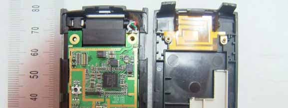
R2NSEC-7089
Jan 28, 2008CDMA 1X EvDo USB Modem
Equipment Class
PCB - PCS Licensed Transmitter
R2NSXC-1280
Nov 08, 2007Single Band CDMA USB Modem
Equipment Class
TNB - Licensed Non-Broadcast Station Transmitter
R2NSEC-3189
Oct 15, 2007CDMA 1X EvDo Express Card
Equipment Class
PCB - PCS Licensed Transmitter