R3X0010819159Remotely Operated Switch
Shenzhen Chuangjiexing Electronics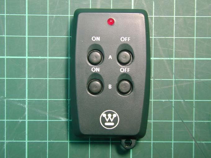
Click to zoom
Application Details
- Equipment Class
- DSC - Part 15 Security/Remote Control Transmitter
- Date of Grant
- Jul 07, 2004
- Application Purpose
- Original Equipment
- Date of Application
- Jul 07, 2004
- Equipment Note
- Remotely Operated Switch
- Frequency Range
- 315.00000000 - 315.00000000
- Country
- China
Documents & Files
Document Text
Text extracted from the exhibit documents filed with the FCC. Open a document above to read the original.
Users Manual
51183 RF Remotely Operated Switch Instruction Manual Instructions Insert the Remote Base’s 3-prong plug into a grounded outlet. If using outdoors, be sure to plug in a GFI approved outlet. Plug appliance into located on bottom of Remote Base. Using the Wireless Remote Control. Press ON button to activate device. Battery Replacement Use 23A 12volt battery (L1028). To replace, screw off back cover on back of Wireless Remote Control. Do not dispose of batteries in fire. Batteries may explode or leak Caution Let the switch hang downward so moisture doesn’t accumulate in the outlet. Install cord and unit above ground level with the receptacle in downward minimum twice vertical length of this unit positioned. Suitable for damp locations. Not for water immersion or for use were directly exposed to water. Store indoors when not in use. Red indicator light is lit when the outdoor receiver/switch is on. DO NOT splice , repair or modify. Unplug when not in use. Fully insert plug. DO NOT use damaged remote sets. Inspect periodically. Use within the electrical rating marked on the remote set. DO NOT plug more than a total 1,000 watts in this remote set. If watts are not marked on appliance, multiply ampere rating(on nameplate) by 125 to determine equivalent watts. Add determined watts for each plugged- in appliance or lamp (sum of watts on bulbs) to find total watts being used. Operating temperature range –30C (-22F) to 45C (113F). FCC warning Warning: Changes or modifications to this unit not expressly approved by the party responsible for compliance could void the user authority to operate the equipment. This device complies with Part 15 of the FCC Rules. Operation is subject to the following two conditions: (1) this device may not cause harmful interference, and (2) this device must accept any interference received including interference that may cause undesired operation. NOTE: This equipment has been tested and found to comply with the limits for a Class B digital device, pursuant to Part 15 of the FCC Rules. These limits are designed to provide reasonable protection against harmful interference in a residential installation. This equipment generates, uses and can radiate radio frequency energy and, if not installed and used in accordance with the instructions, may cause harmful interference to radio communications. However, there is no guarantee that interference will not occur in a particular installation. If this equipment does cause harmful interference to radio or television reception, which can be determined by turning the equipment off and on, the user is encouraged to try to correct the interference by one or more of the following measures: o Reorient or relocate the receiving antenna. o Increase the separation between the equipment and receiver. o Connect the equipment into an outlet on a circuit different from that to which the receiver is needed. o Consult the dealer or an experienced radio/TV technician for help. Repair Center in North Africa The NCC Inc. Brooklyn, NY 1 800 730 3707
Users Manual
RS101 RF Remotely Operated Indoor Switch Instruction Manual Instructions Insert the Remote Base’s 2-prong polarized plug into a polarized outlet. Plug appliance into located on bottom of Remote Base. Using the Wireless Remote Control. Press ON button to activate device. Red indicator light is lit when the indoor receiver/switch is on. Battery Replacement Use 23A 12volt battery (L1028). To replace, screw off back cover on back of Wireless Remote Control. Do not dispose of batteries in fire. Batteries may explode or leak Caution DO NOT splice , repair or modify. Unplug when not in use. Fully insert plug. DO NOT use damaged remote sets. Inspect periodically. Use within the electrical rating marked on the remote set. DO NOT plug more than a total 600 watts in this remote set. If watts are not marked on appliance, multiply ampere rating(on nameplate) by 125 to determine equivalent watts. Add determined watts for each plugged-in appliance or lamp (sum of watts on bulbs) to find total watts being used. Operating temperature range 0C (32F) to 45C (113F). Specifications: 125VAC 60Hz 5A 600Watts Resistive Load FCC warning Warning: Changes or modifications to this unit not expressly approved by the party responsible for compliance could void the user authority to operate the equipment. This device complies with Part 15 of the FCC Rules. Operation is subject to the following two conditions: (1) this device may not cause harmful interference, and (2) this device must accept any interference received including interference that may cause undesired operation. NOTE: This equipment has been tested and found to comply with the limits for a Class B digital device, pursuant to Part 15 of the FCC Rules. These limits are designed to provide reasonable protection against harmful interference in a residential installation. This equipment generates, uses and can radiate radio frequency energy and, if not installed and used in accordance with the instructions, may cause harmful interference to radio communications. However, there is no guarantee that interference will not occur in a particular installation. If this equipment does cause harmful interference to radio or television reception, which can be determined by turning the equipment off and on, the user is encouraged to try to correct the interference by one or more of the following measures: o Reorient or relocate the receiving antenna. o Increase the separation between the equipment and receiver. o Connect the equipment into an outlet on a circuit different from that to which the receiver is needed. o Consult the dealer or an experienced radio/TV technician for help. Repair Center in North Africa The NCC Inc. Brooklyn, NY 1 800 730 3707
Users Manual
TM313R All weather Outdoor Digital Timer Instruction Manual Initial setting 1. Plug the timer to the power outlet, the “C” will appear on the Digit LED. 2. Set Current Time: push the “TIME/MODE” button to set the current time hour. The dot at the bottom right of the Digit LED will appear when the time at PM. 3. Set Timer ON time: push the “ON” button to quite and save above current time setting. The “P” will appear on the Digit LED. Push the “ON” button to set the on time. 4. Set Timer OFF time: push the “OFF” button to quite and save above on time setting. The “E” will appear on the Digit LED. Push the “OFF” button to set the off time. 5. Quite and save initial setting: push the “TIME/MODE” button to quite and save the initial setting. The Digit LED will display the current time and start the normal operating 6. The initial setting must follow the above procedure, otherwise the unit will not start the normal operating to waiting for you to finish it. Review the On/Off setting 1. Review On time: push “ON” button once, the Digit LED will display “P” first and then the On time. 2. Review Off time: push “OFF” button once, the Digit LED will display “E” first and then the Off time. Change the current setting 1. Change the current time: push and hold the “TIME/MODE” button for 2 seconds, the current time display will flash. Push the “TIME/MODE” button to change the current time. 2. Change the On time setting: push and hold the “ON” button for 2 seconds, the On time will display and flash. Push the “ON” button to change the On time setting. 3. Change the Off time setting: push and hold the “OFF” button for 2 seconds, the Off time will display and flash. Push the “OFF” button to change the Off time setting. Manual Override 1. Continuously On: push the “TIME/MODE” button till the Digit LED display “O”. 2. Continuously Off: push the “TIME/MODE” button till the Digit LED display “F”. 3. Timer control: push the “TIME/MODE” button till the Digit LED back to normal time display. Remote Temporary Override 1. Remote Temporary On: push the “ON” button on the remoter, the Digit LED display “Io”. The output will be On temporarily for 12 hours. After 12 hours the timer will return to the Timer Control mode. 2. Remote Temporary Off: push the “OFF” button on the remoter, the Digit LED display “IF”. The output will be Off temporarily for 12 hours. After 12 hours the timer will return to the Timer Control mode. 3. Bypass Remote Temporary Override: push the “TIME/MODE” button on timer unit to change to Timer Control(Normal display), Continuously On(display “O”) or Off(display “F”) mode. Caution: When used outdoors this timer must be plugged into a GFCI protected outlet to provent shock hazard. Let the switch hang downward so moisture doesn’t accumulate in the outlet. Install cord and unit above ground level with the receptacle in downward minimum 1.5m above ground. Suitable for damp locations. Not for water immersion or for use were directly exposed to water. Store indoors when not in use. DO NOT splice , repair or modify. Unplug when not in use. Fully insert plug. DO NOT use damaged remote sets. Inspect periodically. Use within the electrical rating as the specification. DO NOT plug more than a total 1,000 watts in this unit. If watts are not marked on appliance, multiply ampere rating(on nameplate) by 125 to determine equivalent watts. Add determined watts for each plugged-in appliance or lamp (sum of watts on bulbs) to find total watts being used. Operating temperature range –30C (-22F) to 45C (113F). Specifications: 125VAC 60Hz 15A 1,800Watts Resistive Load 8A 1,000W Tungsten Load FCC warning Warning: Changes or modifications to this unit not expressly approved by the party responsible for compliance could void the user authority to operate the equipment. This device complies with Part 15 of the FCC Rules. Operation is subject to the following two conditions: (1) this device may not cause harmful interference, and (2) this device must accept any interference received including interference that may cause undesired operation. NOTE: This equipment has been tested and found to comply with the limits for a Class B digital device, pursuant to Part 15 of the FCC Rules. These limits are designed to provide reasonable protection against harmful interference in a residential installation. This equipment generates, uses and can radiate radio frequency energy and, if not installed and used in accordance with the instructions, may cause harmful interference to radio communications. However, there is no guarantee that interference will not occur in a particular installation. If this equipment does cause harmful interference to radio or television reception, which can be determined by turning the equipment off and on, the user is encouraged to try to correct the interference by one or more of the following measures: o Reorient or relocate the receiving antenna. o Increase the separation between the equipment and receiver. o Connect the equipment into an outlet on a circuit different from that to which the receiver is needed. o Consult the dealer or an experienced radio/TV technician for help. Repair Center in North Africa The NCC Inc. Brooklyn, NY 1 800 730 3707
Block Diagram
TM313R Decode Power and Relay High Frequency Receiver 315MHz Timing Micro-Controller
Block Diagram
51183 B lock diagram Encoder Power with Battery Keyboard and Coding Selector 315MHz Oscillator and Transmitter
Block Diagram
RS101 Decode and Control Power and Relay High Frequency Receiver 315MHz
External Photos
Photo 1: External photo of Tx with four-buttons Photo 2: External photo of Tx with four-buttons Photo 3: External photo o f Tx with two - buttons Photo 4: External photo of Tx with two - buttons
ID Label/Location Info
FCC ID: R3X0010819159 Label location 28mm 25mm
Internal Photos
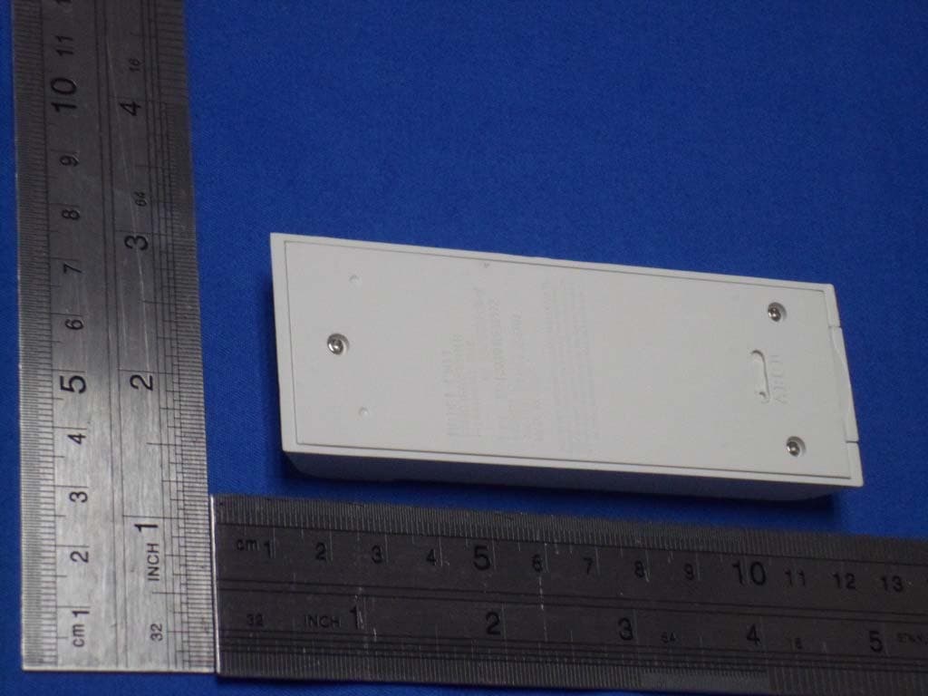
Photo 1: Internal photo of Tx with four-buttons Photo 2: Internal photo of Tx with four-buttons Photo 3: Internal photo of Tx with four-buttons Photo 4: Internal photo of Tx with two-buttons Photo 5: Internal photo of Tx with two-buttons
Operational Description
Technical description Overview This Series of Wireless Remote Switch and Timer product is based on 315MHz radio frequency with Encoding and Decoding Circuit for different receivers and different functions. Encoding and Decoding Circuit provide the ability to distinguish different receivers and different functions within only one radio channel at 315MHz. The power supply for the Transmitter is one 23A 12Volt Battery but the power supply for the receiver is 125VAC for home appliance. Functional Description The receiver of this Series Wireless Remote Switch and Timer uses only one kind of Transmitter. But one Receiver can only work with the Transmitter using the same coding channel. For the Remote Switch Receiver, receiving the signal from the Transmitter will perform switch on (or switch off) action depends on the Transmitter’s command. For Remote Timer Switch, receiving the signal from the Transmitter will override the timing function and perform switch on (or switch off) action depends on the Transmitter’s command.
Test Report
FCC ID. : R3X0010819159 Report No.: EME-040461 Page 1 of 25 EMC TEST REPORT Report No. : EME-040461 Model No. : 51183 Issued Date : July 5, 2004 Applicant : SHENZHEN CHUANGJIEXING ELECTRONICS 3/F., BLDG. A6, LAODONG 1 ST INDUSTRIAL Zone XIXIANG, SHENZHEN Test By : Intertek Testing Services Taiwan Ltd. No. 11, Ko-Tze-Nan Chia-Tung Li, Shiang-Shan District, Hsinchu, Taiwan This test report consists of 25 pages in total. It may be duplicated completely for legal use with the allowance of the applicant. It shall not be reproduced except in full, without the written approval of Intertek Laboratory. The test result(s) in this report only applies to the tested sample(s). Clay Chen Project Engineer Reviewed By Jerry Liu FCC ID. : R3X0010819159 Report No.: EME-040461 Page 2 of 25 Table of Contents Summary of Tests.........................................................................................................3 1. General information..................................................................................................4 1.1 Identification of the EUT....................................................................................4 1.2 Additional information about the EUT................................................................4 1.3 Antenna description............................................................................................5 1.4 Peripherals equipment........................................................................................5 2. Test specifications.....................................................................................................6 2.1 Test standard......................................................................................................6 2.2 Operation mode..................................................................................................6 2.3 Test equipment...................................................................................................7 3. Conducted emission test FCC 15.207........................................................................8 3.1 Operating environment.......................................................................................8 3.2 Test setup & procedure.......................................................................................8 3.3 Emission limit....................................................................................................8 3.4 Conducted emission data FCC 15.207................................................................9 4. Radiated emission test FCC 15.231 (b)...................................................................15 4.1 Operating environment.....................................................................................15 4.2 Test setup & procedure.....................................................................................15 4.3 Radiated emission limit....................................................................................16 4.3.1 Fundamental and harmonics emission limits..................................................16 4.3.2 General radiated emission limit.....................................................................16 4.5 Radiated emission test data FCC 15.231...........................................................18 4.5.1 Fundamental & Harmonics Radiated Emission Data......................................18 4.5.2 Measurement results: frequencies equal to or less than 1 GHz.......................19 4.5.1 Measurement results: frequency above 1GHz................................................23 4.6 Measured bandwidth FCC 15.231(C)...............................................................24 FCC ID. : R3X0010819159 Report No.: EME-040461 Page 3 of 25 Summary of Tests Outdoor Remotely Operated Switch -Model: 51183 FCC ID: R3X0010819159 Test Reference Results Conducted Emission of AC Power 15.207 Complies Radiated Emission test 15.231(b), 15.209 Complies Measured bandwidth 15.231(c) Complies FCC ID. : R3X0010819159 Report No.: EME-040461 Page 4 of 25 1. General information 1.1 Identification of the EUT Manufacturer : SHENZHEN CHUANGJIEXING ELECTRONICS Product : Outdoor Remotely Operated Switch Model No. : 51183 FCC ID. : R3X0010819159 Frequency Range : 315MHz Channel Number : Single Frequency of each channel : 315 MHz Type of Modulation : PCM Power Supply (Tx) : 12 Vdc Power Supply (Rx) : 120Vac, 60Hz Power Cord : N/A Sample Received : Apr. 27, 2004 Test Date(s) : June 24, 2004 ~ June 29, 2004 1.2 Additional information about the EUT The EUT is an Outdoor Remotely Operated Switch, and was defined as information technology equipment. The EUT has only one radio channel 315MHz. It used 16 kinks of different codes for different receiver and used channel label here only for different code, but frequency is still 315MHz. 51183 series model Model no. (Difference just in model no. for marketing purpose) Function Main model 51183 RS103K 28070 28069 Outdoor use Series model RS101 28068 - - Indoor use Series model TM313R 28468R - - Outdoor use+Timing function The difference between 51183, RS101 and TM313R are in receiver, the transmitters are the same. There are two types of transmitters; the difference of them only in the communication code that can be changed by setup the address pins of the demodulation IC of receiver For more detail features, please refer to User ' s manual as file name “Installation guide.pdf” FCC ID. : R3X0010819159 Report No.: EME-040461 Page 5 of 25 1.3 Antenna description The EUT uses a permanently connected antenna. Antenna Gain : 0dBi Antenna Type : Loop antenna Connector Type : N/A 1.4 Peripherals equipment Lamp (1000W for 51183/ TM313R; 600W for RS101) FCC ID. : R3X0010819159 Report No.: EME-040461 Page 6 of 25 2. Test specifications 2.1 Test standard The EUT was performed according to the procedures in FCC Part 15 Subpart C Section 15.231. 2.2 Operation mode The EUT has types of transmitters (includes two buttons and four-buttons). Aft…
Text truncated - open the document above for the full version.
Test Setup Photos
Photo 1: Conducted Emission Test Set-up Photo 2: Conducted Emission Test Set-up
Contact Information
Applicant
William Huo Huo(General Manager)
Technical Contact
Intertek Testing Services, Tiawan Ltd.Jerry Liu
[email protected]+886-3-519-1411
11 Lane 275 Ko Nan 1 Street · Hsinchu · Taiwan
Test Firm
Intertek Testing Services Taiwan Ltd.Alpha Liu
Technical Specifications
| # | Rule Parts | Frequency Range | Power Output |
|---|---|---|---|
| 1 | 15.231 | 315 MHz - 315 MHz | - |
Other Applications from Shenzhen Chuangjiexing Electronics
R3X0010819172
Jan 15, 2013RADIO TRANSMITTER
Equipment Class
DSC - Part 15 Security/Remote Control Transmitter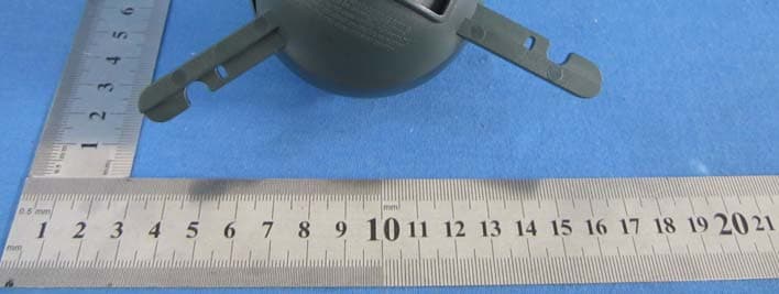
R3X0010819170
Aug 13, 2012RADIO TRANSMITTER
Equipment Class
DSC - Part 15 Security/Remote Control Transmitter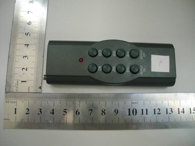
R3X2011081268
Aug 31, 2011Remoter for Wireless Remoter Switch
Equipment Class
DSC - Part 15 Security/Remote Control Transmitter
R3X0010819168
Aug 08, 2010Remoter for Wireless Remoter Switch
Equipment Class
DSC - Part 15 Security/Remote Control Transmitter
R3X0010819160
Aug 06, 2006Remote Controller
Equipment Class
DSR - Part 15 Remote Control/Security Device Transceiver