R3X2011081268Remoter for Wireless Remoter Switch
Shenzhen Chuangjiexing Electronics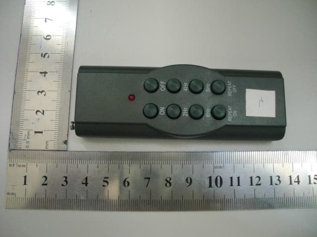
Click to zoom
Application Details
- Equipment Class
- DSC - Part 15 Security/Remote Control Transmitter
- Date of Grant
- Aug 31, 2011
- Application Purpose
- Original Equipment
- Date of Application
- Aug 31, 2011
- Equipment Note
- Remoter for Wireless Remoter Switch
- Frequency Range
- 433.92000000 - 433.92000000
- Country
- China
Documents & Files
Document Text
Text extracted from the exhibit documents filed with the FCC. Open a document above to read the original.
Users Manual
6 Grounded Outlets Lighting Power Center Instructions with Remote Control and Countdown Function ITEM NO: 58170LO Specifications a. Receiver: 125VAC, 60Hz 15A 1875W with 6 Grounded Outlets. b. Transmitter: 433MHz, remote range up to 80 ft. (24.3 m) using (1) CR2032 Lithium 3-volt battery (included). c. 6 ft. (1.82 m) 14AWG SJTW Power Cord With Overload Protector. Questions, call customer service toll-free at 1-877-398-7337 or visit us on the web at www.santasbestcraft.com Printed in China 2010 WARNING: This device complies with Part 15 of the FCC Rules. Operation is subject to the following two conditions: (1) this device may not cause harmful interference, and (2) this device must accept any interference received, including interference that may cause undesired operation. Changes or modifications not expressly approved by the manufacturer could void the user’s authority to operate the equipment. The users manual or instruction manual for an intentional or unintentional radiator shall caution the user that changes or modifications not expressly approved by the party responsible for compliance could void the user’s authority to operate the equipment. NOTE: This equipment has been tested and found to comply with the limits for a Class B digital device, pursuant to Part 15 of the FCC Rules. These limits are designed to provide reasonable protection against harmful interference in a residential installation. This equipment generates, uses and can radiate radio frequency energy and, if not installed and used in accordance with the instructions, may cause harmful interference to radio communications. However, there is no guarantee that interference will not occur in a particular installation. If this equipment does cause harmful interference to radio or television reception, which can be determined by turning the equipment off and on, the user is encouraged to try to correct the interference by one or more of the following measures: • Reorient or relocate the receiving antenna. • Increase the separation between the equipment and receiver. • Connect the equipment into an outlet on a circuit different from that to which the receiver is connected. • Consult the dealer or an experienced radio/TV technician for help. BATTERY INFORMATION AND REPLACEMENT: 1. On the bottom of the remote use your finger to depress the tab to slide out the battery holder. 2. Remove the used battery and insert a new CR2032 Lithium 3-volt battery with the “+” polarity mark facing up. 3. Slide the battery holder back inside so that the tab sets in place. 4. Dispose of old battery properly. WARNING: Keep batteries away from children and pets. Follow the battery manufacturer’s safety and usage instructions. • Remove battery if product is to be left unused for a long time. • Clean the battery contacts prior to battery installation. • Do not dispose of the battery in the fire. Batteries may explode or leak. CAUTION • Risk of Fire. Not for permanent installation. Use only with a total of 12 Ampere maximum Christmas-tree or other seasonal lighting products. Do not install or use this product for more than a 90 day period. • DO NOT PLUG IN MORE THAN THE RATED LOAD. • If using an outdoor-use cord set for an extended period of time (greater than 90 days) please consider hard wiring a permanent outdoor-use receptacle rated for year-round use in the area that power is needed. Please contact a licensed electrician for proper installation of permanent wiring. • After installation, the connector must be kept a minimum of 6 inches (15.2 cm) above the ground. • This is a Radio Frequency (RF) Device. Therefore the range of the transmitter is affected by obstructions, walls and other electronic devices. Notice: Functional Range may be adversely affected by one or more of the following factors: Orientation of the transmitter or receiver, weather, radio frequency interference, low transmitter battery and obstructions between the transmitter and receiver. ATTENTION: INSTRUCTIONS FOR PROPER USE • FULLY EXTEND CORD BEFORE USING • USE WITHIN THE ELECTRICAL RATING MARKED ON THE CORD SET • RATED 125 VOLTS • Unplug when not in use (grasp plug, not cord, to unplug from outlet) • Inspect periodically • Do not splice, repair or modify cord set • Do not walk or drive on cord set • Suitable for use with outdoor appliances-store indoors when not in use • Do not use as permanent source of power • Do not insert stake more than 6 in. (15.2 cm) into the ground • When used outdoors, plug into a GFCI protected receptacle. Receptacle should be mounted in an approved “weatherproof while in use” type outlet box. Install according to all applicable local areas • Do not expose directly to water - rain tight • Do not use device without stake assembled • Do not plug one extension cord into another STAKE ASSEMBLY 1. The upper portion of the stake has been screwed into the bottom of the Power Center Body. 2. Fully insert the lower portion into the upper portion and secure with the 2 internal locking clips. 3. Insert fully assembled stake 6 in. (15.2 cm) into the ground. NOTE: When placing stake into hard or frozen ground: a. Find the desired location. b. Use a screwdriver to make a starter hole. c. Insert stake into the starter hole. 1. 2. a. Power Reset Under normal operating conditions the light under the RESET button should be lit. If unlit there may be no power going to the unit. Check circuit breaker or power switch. If still unlit, then an overload condition may exist. Recheck the load and remove the source of the overload. In pressing the RESET button the light should now come on. Note: Pressing the RESET button at any time or if there is a power outage, all timer settings are cancelled and will need to be set up again. b. Manual Control Pressing the MANUAL button overrides the Auto feature and use of the remote. 1. Press once – The ON indicator is lit providing continuous operation. 2. Press again – No indicator is lit; all power to the unit remains off. 3. Pres…
Text truncated - open the document above for the full version.
Cover Letter(s)
SCS-F18: Project and Product Certification Representative Authorization Letter Page 1 of 2 Rev 2.0 2206 Ringwood Avenue San Jose, CA 95131 Tel: 408-526-1188 Fax: 408-526-1088 Email: [email protected] Project and Product Certification Representative Authorization Letter Revision History Reason for Amendment (current / obsolete) From To Approved Date Initial Release (current) 1.0 1.0 Nov-14-2006 Revised wording (current) 1.0 2.0 Sept–25-2007 SCS-F18: Project and Product Certification Representative Authorization Letter Page 2 of 2 Rev 2.0 Shenzhen Chuangjiexing Electronics 2011-08-30 To: SIEMIC, INC. 2206 Ringwood Avenue, San Jose, CA 95131 USA Dear Sir/Madam, Re: Project and Product Certification Representative Authorization Letter We, Shenzhen Chuangjiexing Electronics hereby authorize SIEMIC, INC. to act as a Certification Body for certifying for the following project(s): Remoter for Wireless Remoter Switch (FCC ID: R3X2011081268) We affirm that between SIEMIC and Shenzhen Chuangjiexing Electronics any difference in understanding, including test plan, measurement methods, applicable standards and relevant procedures and processes have been resolved prior to commencement of testing activities. Sincerely, Client’s signature: Client’s name / title : William Huo/ General Manager Contact information / address TEL:8675527918526 FAX: 8675527900886 E-mail: [email protected] Address :3/F., Bldg. A6, Laodong 1st Industrial Zone, Xixiang, Shenzhen, China
Cover Letter(s)
SCS-F19: Confidentiality Request Letter Page 1 of 2 Rev 2.0 2206 Ringwood Avenue San Jose, CA 95131 Tel: 408-526-1188 Fax: 408-526-1088 Email: [email protected] Confidentiality Request Letter Revision History Reason for Amendment (current / obsolete) From To Approved Date Initial Release (current) 1.0 1.0 Nov-14-2006 Adding CFR 2.459 1.0 2.0 August – 11 - 2008 SCS-F19: Confidentiality Request Letter Page 2 of 2 Rev 2.0 Shenzhen Chuangjiexing Electronics 2011-08-30 To: Federal Communications Commission Authorization and Evaluation Division 7435 Oakland Mills Road Columbia, MD Confidentiality Request regarding application for certification of FCC ID: R3X2011081268 We hereby request confidential treatment of information accompanying this application as outlined below: - Schematics - Block Diagram - Operational Description The above materials contain trade secrets and proprietary information not customarily released to the public. The public disclosure of these materials may be harmful to the applicant and provide unjustified benefits to its competitors. The applicant understands that pursuant to Section 0.457 & 0.459 of the Rules, disclosure of this application and all accompanying documentation will not be made before the date of the Grant for this application. Sincerely, Client’s signature Client’s name / title : William Huo/ General Manager Contact information / address TEL:8675527918526 FAX: 8675527900886 E-mail: [email protected] Address :3/F., Bldg. A6, Laodong 1st Industrial Zone, Xixiang, Shenzhen, China
External Photos
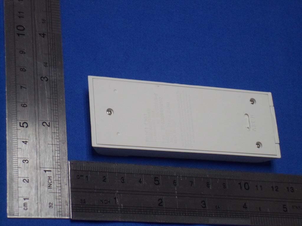
YD620T YD620T YD620T YD620T YD620T-1 YD620T-1 YD620T-2 Note: Their electrical circuit design, PCB layout, components and internal wiring are identical, only the appearance ,keys number and crust’s colour is different.
ID Label/Location Info
Label size Length= 70mm, Width=25mm
ID Label/Location Info
Label Location
Internal Photos
Report No: GTSE11080067301 Global United Technology Services Co., Ltd. Project No.: GTSE110800673RF 2nd Floor, Block No.2, Laodong Industrial Zone, Xixiang Road Baoan District, Shenzhen, China 518102 Telephone: +86 (0) 755 2779 8480 Fax: +86 (0) 755 2779 8960 Page 24 of 24
Test Report
Global United Technology Services Co., Ltd. Report No: GTSE11080067301 Authorized Signature: Robinson Lo Laboratory Manager This report details the results of the testing carried out on one sample. The results contained in this test report do not relate to other samples of the same product and does not permit the use of the GTS product certification mark. The manufacturer should ensure that all products in series production are in conformity with the product sample detailed in this report. This report may only be reproduced and distributed in full. If the product in this report is used in any configuration other than that detailed in the report, the manufacturer must ensure the new system complies with all relevant standards. Any mention of GTS International Electrical Approvals or testing done by GTS International Electrical Approvals in connection with, distribution or use of the product described in this report must be approved by GTS International Electrical Approvals in writing. This document cannot be reproduced except in full, without prior written approval of the Company. Any unauthorized alteration, forgery or falsification of the content or appearance of this document is unlawful and offenders may be prosecuted to the fullest extent of the law. Unless otherwise stated the results shown in this test report refer only to the sample(s) tested and such sample(s) are retained for 90 days only.” 1 Cover Page FCC REPORT Application No: GTSE110800673RF Applicant: Shenzhen Chuangjiexing Electronics Address of Applicant: 3/F., Bldg. A6, Laodong 1st Industrial Zone, Xixiang,Shenzhen, China Equipment Under Test (EUT) EUT Name: Remoter for Wireless Remoter Switch Model No. YD620T, YD620T-1, YD620T-2 Trademark: N/A Operation Frequency: 433.92MHz FCC ID: R3X2011081268 Standards: FCC CFR Title 47 Part 15 Subpart C Section 15.231: 2010 Date of Receipt: 20 August,2011 Date of Test: 20 to 28 August,2011 Date of Issue: 30 August, 2011 Test Result : PASS * * In the configuration tested, the EUT complied with the standards specified above. Report No: GTSE11080067301 Global United Technology Services Co., Ltd. Project No.: GTSE110800673RF 2nd Floor, Block No.2, Laodong Industrial Zone, Xixiang Road Baoan District, Shenzhen, China 518102 Telephone: +86 (0) 755 2779 8480 Fax: +86 (0) 755 2779 8960 Page 2 of 24 2 Contents Page 1 COVER PAGE......................................................................................................................................................... 1 2 CONTENTS.............................................................................................................................................................. 2 3 TEST SUMMARY.................................................................................................................................................... 3 4 GENERAL INFORMATION................................................................................................................................... 4 4.1 CLIENT INFORMATION....................................................................................................................................... 4 4.2 GENERAL DESCRIPTION OF E.U.T................................................................................................................... 4 4.3 E.U.T OPERATION MODE.................................................................................................................................. 5 4.4 TEST FACILITY................................................................................................................................................... 5 4.5 TEST LOCATION................................................................................................................................................ 5 4.6 OTHER INFORMATION REQUESTED BY THE CUSTOMER.................................................................................. 5 4.7 TEST INSTRUMENTS LIST.................................................................................................................................. 6 5 TEST RESULTS AND MEASUREMENT DATA................................................................................................ 7 5.1 ANTENNA REQUIREMENT:................................................................................................................................. 7 5.2 RADIATED EMISSION......................................................................................................................................... 8 5.2.1 Field Strength Of The Fundamental Signal......................................................................................... 10 5.2.2 Spurious Emissions................................................................................................................................. 13 5.3 20DB BANDWIDTH........................................................................................................................................... 15 5.4 DWELL TIME:................................................................................................................................................... 17 6 PHOTOGRAPHS-TEST SETUP PHOTO.......................................................................................................... 19 7 PHOTOGRAPHS - EUT CONSTRUCTIONAL DETAILS............................................................................... 20 Report No: GTSE11080067301 Global United Technology Services Co., Ltd. Project No.: GTSE110800673RF 2nd Floor, Block No.2, Laodong Industrial Zone, Xixiang Road Baoan District, Shenzhen, China 518102 Telephone: +86 (0) 755 2779 8480 Fax: +86 (0) 755 2779 8960 Page 3 of 24 3 Test Summary Test Item Section in CFR 47 Result Antenna requirement 15.203 Passed Field strength of the fundamental signal15.231 (b) Passed Spurious emissions 15.231 (b)/15.209 Passed 20dB Bandwidth 15.231 (c) Passed Dwell time 15.231 (a) Passed Passed: The EUT complies with the essent…
Text truncated - open the document above for the full version.
Test Setup Photos
Report No: GTSE11080067301 Global United Technology Services Co., Ltd. Project No.: GTSE110800673RF 2nd Floor, Block No.2, Laodong Industrial Zone, Xixiang Road Baoan District, Shenzhen, China 518102 Telephone: +86 (0) 755 2779 8480 Fax: +86 (0) 755 2779 8960 Page 19 of 24 6 Photographs-test setup photo Radiated Emission(below 1G) Radiated Emission(above 1G)
Contact Information
Applicant
William Huo Huo(General Manager)
Test Firm
Global United Technology Service Co., LtdRobinson Lo
Technical Specifications
| # | Rule Parts | Frequency Range | Power Output |
|---|---|---|---|
| 1 | 15.231 | 433.92 MHz - 433.92 MHz | - |
Other Applications from Shenzhen Chuangjiexing Electronics
R3X0010819172
Jan 15, 2013RADIO TRANSMITTER
Equipment Class
DSC - Part 15 Security/Remote Control Transmitter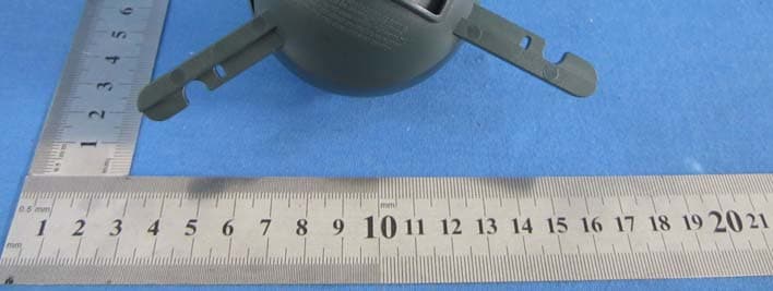
R3X0010819170
Aug 13, 2012RADIO TRANSMITTER
Equipment Class
DSC - Part 15 Security/Remote Control Transmitter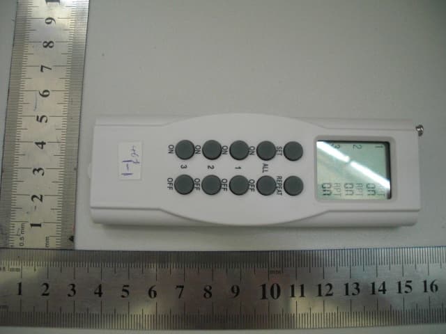
R3X0010819168
Aug 08, 2010Remoter for Wireless Remoter Switch
Equipment Class
DSC - Part 15 Security/Remote Control Transmitter
R3X0010819160
Aug 06, 2006Remote Controller
Equipment Class
DSR - Part 15 Remote Control/Security Device Transceiver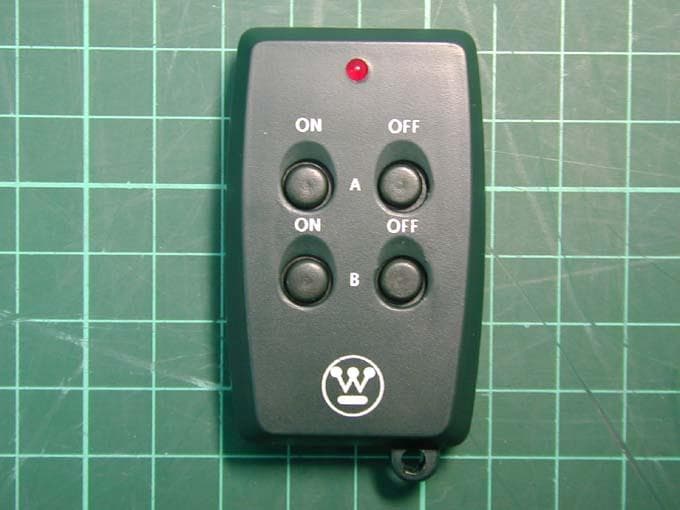
R3X0010819159
Jul 07, 2004Remotely Operated Switch
Equipment Class
DSC - Part 15 Security/Remote Control Transmitter