R47F2M03GXABluetooth module
Free2move AB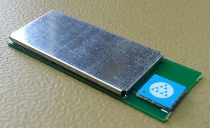
Click to zoom
Application Details
- Equipment Class
- DSS - Part 15 Spread Spectrum Transmitter
- Date of Grant
- Jan 23, 2014
- Application Purpose
- Original Equipment
- Date of Application
- Jan 23, 2014
- Equipment Note
- Bluetooth module
- Frequency Range
- 2402.00000000 - 2480.00000000
- Company
- Free2move AB
- Country
- Sweden
Documents & Files
Document Text
Text extracted from the exhibit documents filed with the FCC. Open a document above to read the original.
Users Manual
Rev: e www.free2move.net Extended range Bluetooth Module - F2M03GXA Datasheet BLUETOOTH is a trademark owned by Bluetooth SIG, Inc., U.S.A. and licensed to Free2move Features • Fully qualified product with modular approval • Bluetooth™ v2.0+EDR • Certified for CE, FCC, and IC • Integrated high output antenna • Transmit power up to +18 dBm • Class1/ 2/ 3 Configurable • Range: up to 500m (line of sight) • Piconet and Scatternet capability, • Supports up to 7 slaves • Industrial temperature range -40 ° C to +85 ° C • USB v2.0 compliant • Extensive digital and analog I/O interface • PCM interface for up to 3 simultaneous voice channels • Large external memory for custom applications • Support for 802.11b/g Co-Existence • RoHS compliant Applications • Industrial and domestic appliances • Cable replacement • Medical systems • Automotive applications • Stand-alone sensors • Embedded systems • Cordless headsets • Computer peripherals (Mice, Keyboard, USB dongles, etc.) • Handheld, laptop and desktop computers • Mobile phones General Description F2M03GXA is Free2move’s top of the line embedded Bluetooth™ v2.0+EDR module with exceptional wireless transmission characteristics. The module provide a fully Bluetooth™ compliant device for data and voice communications. With a transmit power of up to +18 dBm and a receiver sensibility of down to –89 dBm the F2M03GXA is suitable for the most demanding applications. Developers can easily implement a wireless solution into their product even with limited knowledge in Bluetooth™ and RF. The module is fully Bluetooth™ v2.0+EDR qualified and is certified according to CE, FCC, and IC, which give fast and easy Plug-and-Go implementation and short time to market. The F2M03GXA comes with an on board highly efficient omni-directional antenna that simplifies the integration for a developers Bluetooth™ solution. RoHS RoHSRoHS RoHS COMPLIANT Rev: e © 2030 Free2move AB Page 2(45) Extended range Bluetooth Module - F2M03GXA Datasheet Table of contents 1 Device pinout....................................................................................................................... 3 2 Device terminal functions ................................................................................................... 4 3 Electrical Characteristics ................................................................................................... 5 3.1 Current consumption .................................................................................................................. 6 4 Radio Characteristics ......................................................................................................... 8 Firmware versions ...................................................................................................................... 9 4.1 Wireless UART ........................................................................................................................ 11 4.2 HCI .......................................................................................................................................... 16 5 Device terminal description .............................................................................................. 19 5.1 UART Interface ........................................................................................................................ 19 5.2 USB Interface .......................................................................................................................... 21 5.3 Serial Peripheral Interface ........................................................................................................ 25 5.4 I 2 C Interface ............................................................................................................................. 25 5.5 PCM ........................................................................................................................................ 26 5.6 PIOs ........................................................................................................................................ 33 5.7 Power supply ........................................................................................................................... 34 6 Application information .................................................................................................... 35 6.1 Recommended land pattern ..................................................................................................... 35 6.2 Layout guidelines ..................................................................................................................... 36 6.3 Typical application schematic ................................................................................................... 37 7 Package information ......................................................................................................... 38 7.1 F2M03GXA .............................................................................................................................. 38 8 Certifications ..................................................................................................................... 39 8.1 Bluetooth ................................................................................................................................. 39 8.2 CE ........................................................................................................................................... 39 8.3 FCC ......................................................................................................................................... 39 8.4 Industry Canada (IC) ................................................................................................................ 39 9 RoHS And REACH Statement ........................................................................................... 40 10 Tape and Reel information ...........................................…
Text truncated - open the document above for the full version.
RF Exposure Info
Date Reference Page REPORT 2013-06-28 3P03521-F15C 1 (2) Appendix 8 SP Technical Research Institute of Sweden RF exposure evaluation: Mobile equipment FCC 47 CFR part 15.247 (i) / RSS-102 2.5.1 Date 2013-06-18 Temperature 22 °C ± 3 °C Humidity 49 % ± 5 % Procedure Systems operating under the provisions of this section shall be operated in a manner that ensures that the public is not exposed to radio frequency energy levels in excess limit for maximum permissible exposure. In accordance with 47 CFR FCC Part 2 Subpart J, section 2.1091 this device has been defined as a mobile device whereby a distance of 0.2 m normally can be maintained between the user and the device. Results The following formula was used to calculate the RF exposure, Pd = Pout x G/(4 x π x r 2 cm ) where, Pd = power density in mW/cm 2 Pout = output power to antenna in mW G = gain of antenna in linear scale π = 3.1416 r = distance between observation and center of the radiator in cm From the peak EUT RF output power, the minimum mobile separation distance, r=20 cm, as well as the gain of the used antenna, the RF power density can be obtained. The maximum conducted peak output power from appendix 5 was used for calculation of MPE. Antenna Gain (dBi) Antenna Gain (numeric) Peak output power (mW) Power density, Pd [S] (μW/cm 2 ) Limit of power density (μW/cm 2 ) 2 1.56 60.2 0.089 1000 Date Reference Page REPORT 2013-06-28 3P03521-F15C 2 (2) Appendix 8 SP Technical Research Institute of Sweden Limits (A) Limits for Occupational/Controlled Exposure Frequency range (MHz) Electric field strength [E] (V/m) Magnetic field strength [H] (A/m) Power density [S] (mW/cm 2 ) Averaging time |E| 2 , |H| 2 or S (minutes) 0.3-3.0 614 1.63 (100)* 6 3.0-30 1842/f 4.89/f (900/f)* 6 30-300 61.4 0.163 1.0 6 300-1500 F/300 6 1500-100,000 5 6 (B) Limits for General Population/Uncontrolled Exposure Frequency range (MHz) Electric field strength [E] (V/m) Magnetic field strength [H] (A/m) Power density [S] (mW/cm 2 ) Averaging time |E| 2 , |H| 2 or S (minutes) 0.3-1.34 614 1.63 (100)* 30 1.34-30 824/f 2.19/f (180/f)* 30 30-300 27.5 0.073 0.2 30 300-1500 F/1500 30 1500-100,000 1.0 30 Note: f=frequency in MHz, *Plane-wave equivalent power density According to RSS-102 2.5.1, SAR evaluation is required if the separation distance between the user and the radiating element of the device is less than or equal to 20 cm, except when the device operates as follows: • above 2.2 GHz and up to 3 GHz inclusively, and with output power (i.e. the higher of the conducted or radiated (e.i.r.p.) source-based, time-averaged output power) that is less than or equal to 20 mW for general public use and 100 mW for controlled use; Complies? Yes
Test Report
Date Reference Page REPORT 2013-10-28 3P03521-F15C Rev1 1 (3) Rev 1: 2014-01-13 Appendix 1 SP Technical Research Institute of Sweden Performance test and requirements The tests were performed in order to verify that the F2M03GXA radio module meets the electromagnetic compatibility requirements of FCC 47 CFR part 15 C. Test facility The used anechoic chamber is compliant with the requirements of section 2.948 of the FCC rules and listed, registration number 96866, as a facility accepted for certification under parts 15 and 18. The site complies with RSS Gen, Issue 2 and is accepted by Industry Canada for the performance of radiated measurements, IC-file number 3482A-2. Test object Transceiver: F2M03GXA FHSS transceiver module Antenna: Integral, PCB Antenna gain: 2 dB Frequency range: 2402-2480 MHz Frequencies used during test: 2402 MHz 2441 MHz 2480 MHz Modulations: GFSK, π/4DQPSK, 8DPSK Max power settings (used during the test): GFSK +18 dBm (setting #30) π/4DQPSK and 8DPSK +5 dBm (setting #7) Number of hopping frequencies: 79 Channel hopping separation: 1 MHz Data rates: GFSK 1 Mbits/s π/4 DQPSK 2 Mbit/s 8DPSK 3 Mbit/s Supply voltage: Nominal: 3.7 V DC The EUT was powered by a Lithium hybrid battery cell. Used samples Radiated samples: #34, #36, #40 Conducted sample, temporary antenna connector: #35 Measurement Appendix Sample Duty cycle measurements 2 #34, #36 Carrier frequency separation and 20 dB BW 3 #35 Number of hopping frequencies and dwell time 4 #35 Max peak conducted power 5 #35 20 dBc below fundamental 6 #35 Restricted bands of operation 7 #34, #35, #36 RF Safety 8 #35 20 dB bandwidth 9 #35 Occupied bandwidth 10 #35 Band Edge 11 #34; #36, #40 Date Reference Page REPORT 2013-10-28 3P03521-F15C Rev1 2 (3) Rev 1: 2014-01-13 Appendix 1 SP Technical Research Institute of Sweden Measurement equipment Measurement equipment Calibration Due SP number Test site Edison 2013-11 504 114 R&S ESU40 Signal Analyser 2013-07 901 385 R&S ESU26 Signal Analyser 2013-12 902 210 R&S ESI40 Signal Analyser 2013-07 (2014-07 for measurements performed 2013-11-14) 503 125 Antenna Schaffner CBL 6143 2013-10 504 079 Horn antenna EMCO 3115 2014-01 501 548 Boonton power meter 2013-11 503 144 Boonton power sensor 2013-11 503 146 Standard gain horn Flann 16240-25 - 503 939 Standard gain horn Flann 18240-25 - 503 900 Standard gain horn Flann 20240-20 - 503 674 Low Noise Amplifier Miteq 2013-08 503 277 Low Noise Amplifier Miteq 2013-08 504 160 High pass filter Wainwright WHKY 2013-08 503 739 TTE Blocking filter 2013-07 503 575 High pass filter Wainwright 2013-08 504 200 Multimeter Fluke 2013-06 503 498 Multimeter Fluke 83 2013-06 501 522 Temperature and humidity meter Testo 625 2014-06 504 117 Temperature and humidity meter Testo 2013-06 503 418 Operational test mode Justification measurements were performed with rotation of the EUT through three orthogonal axes, see photos in Appendix 12, and with the different modulations in order to determine worst case configuration. GFSK was deemed to represent worst case modulation. The EUT was tested as a module powered by battery. The test was performed with GFSK modulation if not otherwise stated. Settings of the EUT were performed with an external computer with help of dedicated software. For duty cycle measurements see appendix 2. During test the EUT has a duty cycle of 77 %. The duty cycle correction factor was calculated to 20 log (2.89 / 3.75 ) = -2.3 dB. The PRF was calculated to PRF = 1/T = 1/3.75 ms = 270 Hz. Since the RBW of 1MHz is > PRF, QP-detector was used without any correction for pulse desensitization. Date Reference Page REPORT 2013-10-28 3P03521-F15C Rev1 3 (3) Rev 1: 2014-01-13 Appendix 1 SP Technical Research Institute of Sweden Uncertainties Measurement and test instrument uncertainties are described in the quality assurance documentation ”SP QD 10885”. The measurement uncertainties can be found in the table below. The uncertainties are calculated with a coverage factor k=2 (95% level of confidence). The measurement uncertainties can be found in the table below: Method Uncertainty Radiated emission, 30 – 1000 MHz 4.8/5.6 dB (V/H-pol) Radiated emission, 1 – 40 GHz 2.6 dB Compliancy evaluation is based on a shared risk principle with respect to the measurement uncertainty. Reservation The test results in this report apply only to the particular test object as declared in the report. Delivery of test object The test objects were delivered: 2013-05-29 Test participant Peo Karlsson Free2move Test engineers Fredrik Isaksson, Martin Nilsson SP Date Reference Page REPORT 2013-10-28 3P03521-F15C Rev1 1 (2) Rev 1: 2014-01-13 Appendix 2 SP Technical Research Institute of Sweden Duty cycle measurements Date 2013-06-18 Temperature 21°C ± 3 °C Humidity 18 % ± 5 % Test set-up and procedure The measurements were performed according to ANSI C63.10-2009. The test was performed with FHSS disabled, normal duty cycle and with GFSK modulation. The radiated measurements were performed in a semi anechoic chamber. The measurements were performed with the EUT-axis, antenna at the position, polarization and the turntable in the position giving the highest level at the fundamental, see Appendix 5. The antenna distance was 3.0 m. Measurement equipment SP number Semi anechoic chamber, Edison 504 114 Spectrum analyzer R&S ESU 26 902 210 Horn antenna EMCO 3115 501 548 Multimeter Fluke 83 501 522 Temperature and humidity meter Testo 625 504 117 Results The duty cycle measurements can be found in the diagram below: Diagram 1: Tx on: 2.89 ms Period time: 3.75 ms Complies? N/A Date Reference Page REPORT 2013-10-28 3P03521-F15C Rev1 2 (2) Rev 1: 2014-01-13 Appendix 2 SP Technical Research Institute of Sweden Diagram 1 Duty cycle: 2.89 ms/ 3.75 ms = 0.77 Ref 100 dBμVAtt 10 dB * Center 2.44109 GHz2.25 ms/ 1 AP CLRWR A TRG PS 3DB RBW 1 MHz VBW 3 MHz SWT 22.5 ms AC 0 10 20 30 40 50 60 70 80 90 100 1 Marker 1 [T1 ] 82.26 dBμV 2.896635 ms 2 Marker 2 [T1 ] 82.32 dBμV 3.750000 ms 3 Marker 3 […
Text truncated - open the document above for the full version.
Test Setup Photos
Date Reference Page REPORT 2013-06-28 3P03521-F15C 1 (3) Appendix 12 SP Technical Research Institute of Sweden Photos The test set-up during the radiated tests can be seen in the pictures below. X-axis Date Reference Page REPORT 2013-06-28 3P03521-F15C 2 (3) Appendix 12 SP Technical Research Institute of Sweden Y-axis Z-axis
Contact Information
Applicant
Peo Karlsson(Mr.)
Technical Contact
Test Firm
SP Technical Research Institute of SwedenMagnus Winehem
Technical Specifications
| # | Rule Parts | Frequency Range | Power Output |
|---|---|---|---|
| 1 | 15C | 2.40 GHz - 2.48 GHz | 60.20 mW |
Other Applications from Free2move AB
R47F2M03GX
Jul 09, 2007Low power Bluetooth Multimedia Module with antenna
Equipment Class
DSS - Part 15 Spread Spectrum Transmitter
R47F2M03GL
Jul 05, 2007Low power Bluetooth Multimedia Module with antenna
Equipment Class
DSS - Part 15 Spread Spectrum Transmitter
R47F2M01C1
May 24, 2005Serial cable replacement and communicat. handheld
Equipment Class
DSS - Part 15 Spread Spectrum Transmitter