R4UFLEXSERIESRemote Control System
Advanced Radiotech Corporation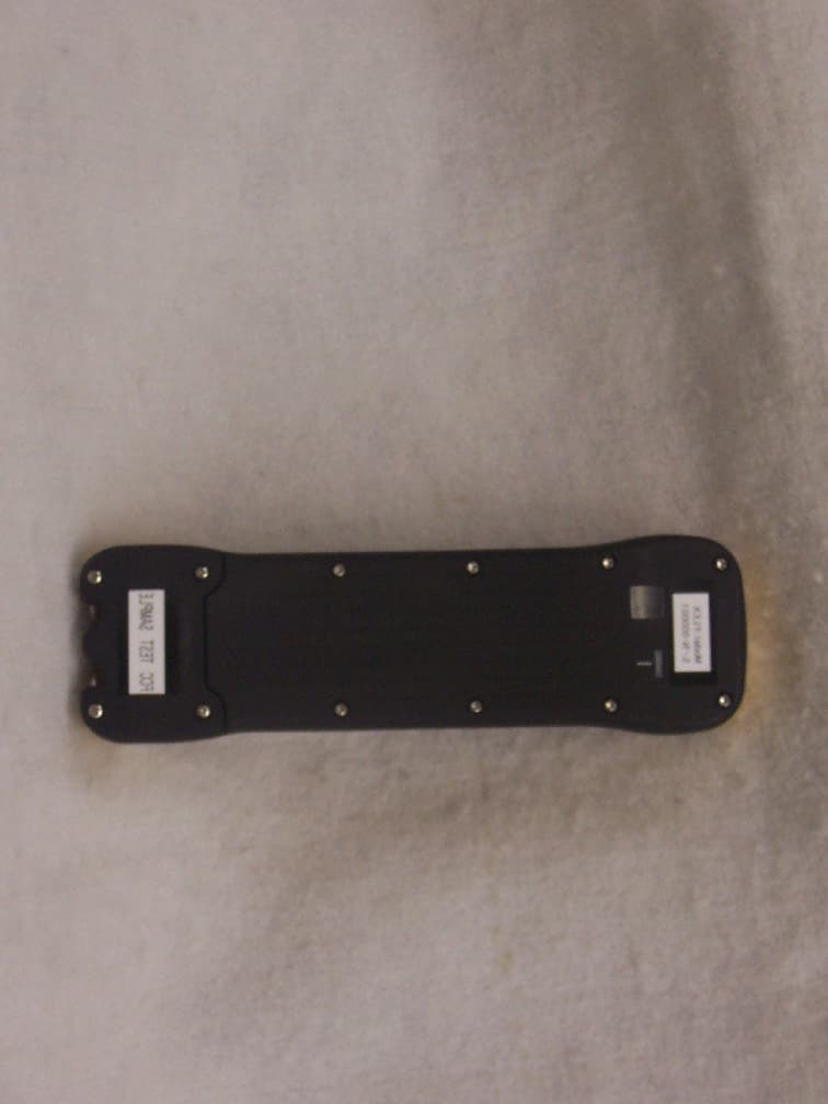
Click to zoom
Application Details
- Equipment Class
- DSC - Part 15 Security/Remote Control Transmitter
- Date of Grant
- May 20, 2004
- Application Purpose
- Original Equipment
- Date of Application
- May 20, 2004
- Equipment Note
- Remote Control System
- Frequency Range
- 433.00000000 - 433.00000000
- Country
- Taiwan
Documents & Files
Document Text
Text extracted from the exhibit documents filed with the FCC. Open a document above to read the original.
Users Manual
FLEX User’s Manual 1 Table of Contents Page 1. Introduction 2 2. Radio Controlled Safety 3 3. General System Information A. Transmitter Handset 1. External Illustration 4 2. Internal Illustration 5 B. Receiver Unit 1. External Illustration 6 2. Internal Illustration 7 4. Function Settings A. Transmitter Handset 1. System Channel Settings 8 2. Pushbutton Functions with LED Display Settings 9~13 B. Receiver Unit 1. System Channel Settings 13 2. Output Relay Configurations 14~15 3. Dip-switch Settings 16~17 4. Jumpers Settings 18 5. System Channels Table 19 6. Receiver Installation A. Output Relay Contact Diagrams 20 B. Receiver Mounting 1. Pre-installation Precautions 21 2. Step-by-Step Installation 21~22 3. System Testing 22 7. Operating Procedure A. Transmitter Operation 23 B. Status Light Indicators & Warnings 1. Transmitter STATUS Light Indication 24 2. Receiver STATUS Light Indication 25 3. Receiver SQ Light Indication 25 4. Receiver Power Light Indication 25 5. Receiver COM Light Indication 25 C. Trouble Shooting Tips 26 8. System Specification 27 9. Spare Parts 28 2 1. Introduction The ARC FLEX radio remote control systems are designed for control of industrial equipment and machinery such as overhead traveling cranes, jib cranes, gantry cranes, tower cranes, electric hoists, winches, monorails, conveyor belts, mining equipment and other material handling equipment where wireless control is preferred. Each FLEX system consists of a transmitter handset and receiver unit. Other standard-equipped accessories include transmitter waist belt, “AA” batteries, compass direction decal sheet and user’s manual. List of notable features include: * 62 user-adjustable channels – no more fixed channels and fragile quartz crystals to break. * Over one million sets of unique ID codes (20-bit) – unlike many other radio control systems on the market, the FLEX system never repeats ID codes. * Advanced microprocessor controls with 32-bit CRC and Hamming Codes programming – ultra fast, safe, precise and error-free encoding and decoding. * Ultra-durable transmitter push button – good for up to one million press cycles. * Ultra power-saving transmitter – requires only two “AA” Alkaline or rechargeable batteries (2000mA or above) for more than 100 hours of continuous operating time between replacements or recharging. * Ultra durable nylon and fiberglass composite enclosures – resist breakage from high impacts and frequent drops; no more fragile casings to replace. * 100% water and shock resistant * Adjustable waist belt for easy carry and operation. 3 2. Radio Controlled Safety Flex radio remote control system should be operated by persons with sufficient amount of knowledge and skill in crane operation and safety. Persons being trained to operate a radio remote controlled crane should possess the knowledge of all hazards peculiar to radio remote controlled crane operation, ability to judge distance and moving objects, equipment capacity and radio remote controlled safety rules. Radio remote controlled cranes should not be operated by any person with insufficient eyesight, hearing, illness, and under influence of drugs and medications that may cause loss of crane control. Below are some general operating safety tips that should be strictly followed when operating a radio remote controlled crane. 1. Prior to crane operation always check the transmitter handset for any damage that might inhibit proper crane operation. 2. Always check if the red emergency stop button is working properly prior to crane operation. 3. Check the battery status LED on the transmitter for any signs of low battery power. 4. Check the Status LED on the transmitter for any signs of irregularities. Please refer to the “Transmitter Status Light Indicators & Warnings” on page 24. 5. The crane limit switches should be checked prior to crane operation or at the beginning of each shift. When checking limit switches the hoist should be centered over an area free of personnel and equipment. 6. If power to the crane is removed, the operator should turn off the transmitter power immediately until the power to the crane is restored. 7. If the crane fails to respond properly to operator’s command the operator should stop operation, turn the transmitter power off, and then report the condition to their supervisor. 8. The transmitter power should be turned off after each use. If the transmitter handset is not in use always turn the power off and stored it in a safe or designated location. Never leave the transmitter handset unattended in the working area. 9. Even though Flex system is capable of allowing up to four systems with same channel in use without interfering with one another, it is always a good practice not to use the same RF channel as any other Flex systems in use within a distance of 200 feet. 10. Never operate a crane or equipment with two identical channel and ID transmitter handsets at the same time within the same facility. 4 3. General System Information A. TRANSMITTER HANDSET 1. External Illustration Fig. 01 Fig. 02 1. Emergency Stop Button 8. Push button #12 15. Strap Holder 2. Power Key Switch 9. Push button #1 16. System Information 3. Push button #2 10. Push button #3 17. System Channel 4. Push button #4 11. Push button #5 18. Crane Number 5. Push button #6 12. Push button #7 19. Battery Cover 6. Push button #8 13. Push button #9 20. FCC/CE Information 7. Push button #10 14. Push button #11 5 2. Internal Illustration Fig. 03 Fig. 04 1. Arial Antenna 5 I-CHIP 2. Transmitting Board 6 Function Dip-Switch 3. Status LED Display 7 Channel Dip-Switch 4. Function LED Display 6 B. RECEIVER UNIT 1. External Illustration Fig. 05 1. Shock Absorber 6. COM LED Display 2. External Antenna BNC Jack 7. Output Contact Diagram 3. Power LED Display 8. System Information 4. Status LED Display 9. Cable Gland/ Cord Grip 5. SQ LED Display 7 2. Internal Illustration Fig. 06 1. AC Line Filter 4. Decoder Board 2. Power Transformer 5. Relay Board 3. Rece…
Text truncated - open the document above for the full version.
Operational Description
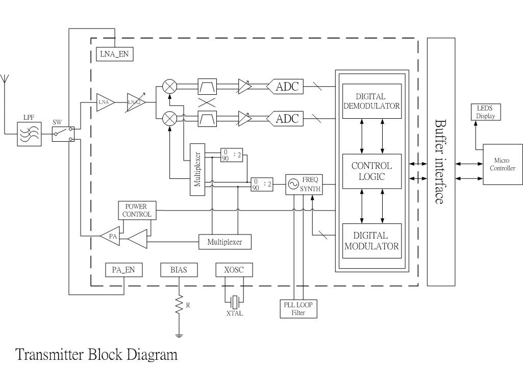
Tel: +886-7-812-8112 Fax: +886-7-812-8119 1F, 288-3, Hsin Ya Road, Chien Chen District, Kaohsiung City, Taiwan, R.O.C. Operational Description ARC Flex wireless radio remote control system is used to control an overhead traveling crane. The Flex system consists of a transmitter handset and a receiver unit. The receiver unit is installed on the overhead traveling crane, inside the control panel. The receiver controls the opening and closure of magnetic contactors inside crane’s control panel, thus controlling the forward and reverse motion of crane’s electric motors. Press the push button on the transmitter handset will energize the designated magnetic contactor on the crane and thus able the crane to move in many directions. There are total of 12 push buttons on the Flex transmitter handset, which is able to control up to 6 motions or 6 electric motors.
Test Report
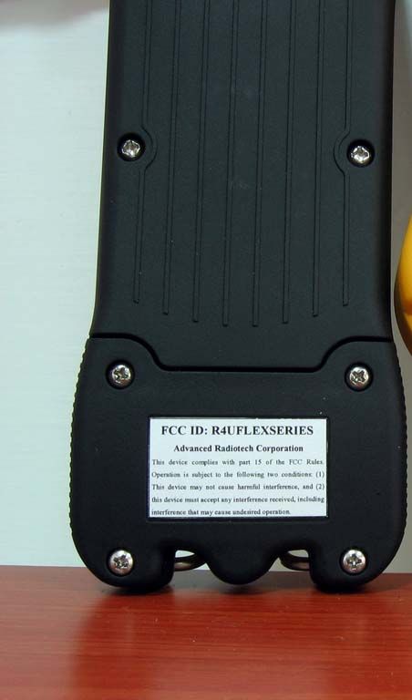
APPLICANT Advanced Radiotech Corporation 1F, 288-3, Hsin Ya Road, Chien Chen District Kao Siung City, Taiwan MANUFACTURER Advanced Radiotech Corporation 1F, 288-3, Hsin Ya Road, Chien Chen District Kao Siung City, Taiwan TEST SPECIFICATION: FCC Rules and Regulations Part 15, Subpart C, Para. 15.231 TEST PROCEDURE: ANSI C63.4:2001 TEST SAMPLE DESCRIPTION BRANDNAME: Advanced Radiotech Corporation Model Number: FLEX TYPE: Pulsed RF POWER REQUIREMENTS: 3 VDC via 2 “AA” Batteries FREQUENCY OF OPERATION: 433 MHz TESTS PERFORMED Para. 15.231(b), Radiated Emissions, Fundamental and Harmonics Para. 15.231(b), Radiated Emissions, Spurious Case Para. 15.35, Duty Cycle Determination Para. 15.231(c), Occupied Bandwidth REPORT OF MEASUREMENTS Applicant: Advanced Radiotech Corporation Brand Name: ARC Device: Pulsed RF FCC ID: R4UFLEXSERIES Power Requirements: 3 VDC via 2 “AA” Batteries Applicable Rule Section: Part 15, Subpart C, Section 15.231 Test Report No. R-10309-1 FCC ID: R4UFLEXSERIES REPORT OF MEASUREMENTS (continued) TEST RESULTS 15.231 (a): This device is used as a remote control transmitter. 15.231 (a)(1) & The transmitter is manually operated and ceases transmission within 5 15.231(a)(2): seconds after deactivation. 15.231 (a)(3): The transmitter does not perform periodic transmissions. 15.231 (b): The fundamental field strength did not exceed 10,966 ΦV/M (Average) at a test distance of 3 meters. In addition, the requirements of section 15.35 for averaging pulsed emissions and for limiting peak emissions were met. The field strength of harmonic and spurious emissions did not exceed 1,095 ΦV/M (AVERAGE). DETERMINATION OF FIELD STRENGTH LIMITS The field strength limits shown below are found in Section 15.231. Frequency Limit F1 = 260 3750 = L1 Fo = 433.92 Lo F2 = 470 12500 = L2 The formula below was utilized to determine the limits: Limit = L1 + [(Fo-F1)(L2-L1)/(F2-F1)] Solving yields: Fundamental Limit = 10,966 ΦV/M (AVERAGE) @ 3 Meters Harmonic Limit = 1,097 ΦV/M (AVERAGE) @ 3 Meters Test Report No. R-10309-1 FCC ID: R4UFLEXSERIES DUTY CYCLE DETERMINATION The unit’s RF output was directly coupled to the input of the spectrum analyzer. The analyzer was set for a frequency span of 0Hz. The sweep time was then adjusted in order to display one full pulse train. The transmitter on time was then summed and compared to the time for one full cycle in order to obtain the duty cycle. Transmitter On Time = 33.2 milliseconds (maximum) Transmitter Cycle Time = 100 milliseconds Transmitter Duty Cycle = 33.2 % See separate e-file for plots named dutycycle.pdf for additional information. SPECTRUM ANALYZER DESENSITIZATION CONSIDERATIONS Due to the nature of the emissions being measured, care was taken to ensure that the resolution bandwidth of the spectrum analyzer was adequate to provide accurate measurements. The following formula was utilized: Setting pulse desensitization equal to zero and utilizing the minimum observed pulse width of 33.2 milliseconds yields a minimum required bandwidth of 20 Hz. FCC specified bandwidths of 100kHz and 1MHz were utilized below and above 1GHz, respectively. GENERAL NOTES 1. All readings were taken utilizing a peak detector function at a test distance of 3 meters. 2. The duty cycle was applied to the peak readings in order to determine the average value of the emissions. 3. The frequency range was scanned from 30 MHz to 4.3 GHz. All emissions not reported were more than 20 dB below the specified limit. Test Report No. R-10309-1 FCC ID: R4UFLEXSERIES Equipment List FCC 15.231 Transmitter Testing EN Type Manufacturer Description Model No. Cal Date Due 067 Open Area Test Site Retlif 3 Meter RNY 10/1/2003 10/1/2006 128 Double Ridged Guide Electro-Mechanics 1 GHz - 18 GHz 3105 6/13/2003 6/13/2004 133 Broadband Pre-Amplifier Electro-Metrics 10 kHz - 1 GHz, 26dB BPA-1000 6/12/2003 6/12/2004 141 Spectrum Analyzer Hewlett Packard 100 Hz - 40 GHz 8566B 1/26/2004 7/26/2004 141A Graphics Plotter Hewlett Packard N/A 7470A 2/9/2004 2/9/2005 141B Quasi-Peak Adaptor Hewlett Packard 100 Hz - 1 GHz 85650A 1/26/2004 7/26/2004 206B 6.0 dB Attenuator Texscan 0 - 1.0 GHz FP-50 - 6 dB 6/12/2003 6/12/2004 543 Preamplifier Hewlett Packard 1.0 GHz - 26.5 GHz 8449B 7/24/2003 7/24/2004 617 Interference Analyzer Electro-Metrics 10 kHz - 1 GHz EMC-30 9/30/2003 9/30/2004 Test Report No. R-10309-1 FCC ID: R4UFLEXSERIES FCC 15.231(b) RADIATED EMISSIONS, FUNDAMENTAL & SPURIOUS CASE (See separate e-file named Refundharm & REspur.pdf) Test Report No. R-10309-1 FCC ID: R4UFLEXSERIES FCC 15.231(c) OCCUPIED BANDWIDTH (See separate e-file named occbw.pdf) Test Report No. R-10309-1 FCC ID: R4UFLEXSERIES FCC 15.231(c) DUTY CYCLE (See separate e-file named dutycycle.pdf) Test Report No. R-10309-1 FCC ID: R4UFLEXSERIES Test Setup Photograph
Contact Information
Applicant
Tom Jou
Technical Contact
Retlif Testing LaboratoriesThomas J Schneider
[email protected]631 737 1500
795 Marconi Avenue · Ronkonkoma, New York · United States
Non-Technical Contact
Retlif Testing LaboratoriesMichelle White
[email protected]631 737 1500
Test Firm
Retlif Testing LaboratoriesMichael Bozza
Technical Specifications
| # | Rule Parts | Frequency Range | Power Output |
|---|---|---|---|
| 1 | 15.231 | 433 MHz - 433 MHz | - |
Other Applications from Advanced Radiotech Corporation
R4UARCRFM2400RX
Sep 11, 2024406RX(2.4GHz)
Equipment Class
DSS - Part 15 Spread Spectrum TransmitterR4UARCRFM2400TX
Sep 11, 2024406TX(2.4GHz)
Equipment Class
DSS - Part 15 Spread Spectrum Transmitter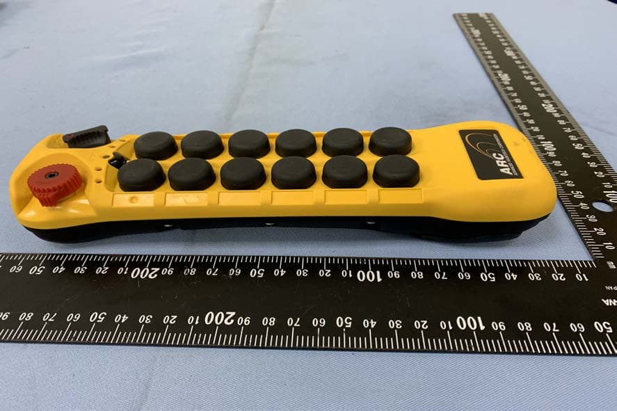
R4UARCFLEXEPH
Jan 07, 2020Industrial radio remote control system
Equipment Class
DSR - Part 15 Remote Control/Security Device Transceiver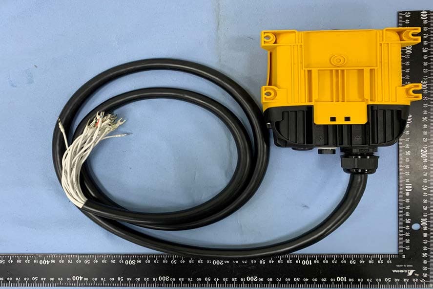
R4UARCFLEXHRX
Jan 07, 2020Industrial radio remote control system
Equipment Class
JAB - Part 15 Class B Digital Device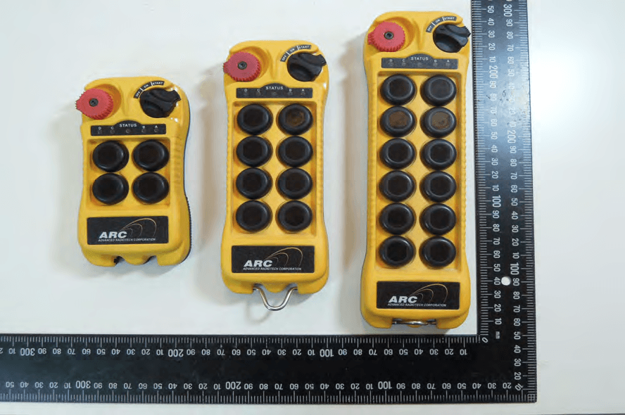
R4UARCFLEXEX
Oct 06, 2015Industrial radio remote control systems
Equipment Class
DSC - Part 15 Security/Remote Control Transmitter