R4WRRAP01Turning
Turning Technologies, LLC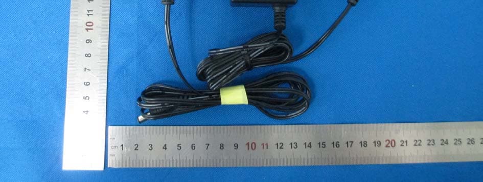
Click to zoom
Application Details
- Equipment Class
- DTS - Digital Transmission System
- Date of Grant
- Mar 23, 2015
- Application Purpose
- Original Equipment
- Date of Application
- Mar 23, 2015
- Equipment Note
- Turning
- Frequency Range
- 2422.00000000 - 2452.00000000
- Company
- Turning Technologies, LLC
- Country
- United States
Documents & Files
Document Text
Text extracted from the exhibit documents filed with the FCC. Open a document above to read the original.
Users Manual
Turning Quick Start Guide Overview Turning is a high performance Wi‐Fi Access Point combined with a Turning Technologies RF receiver. As an access point, Turning supports the 802.11 a/b/g/n IEEE standard and will support 60 simultaneous client connections in the 2.4GHz ISM band. In addition to Wi‐Fi access point functionality, the Turning Technologies RRDR ‐01 RF dual‐radio receiver supports data collection from Turning Technologies response devices and polling applications. The included storage also provides delivery of classroom content regardless of connectivity external to the classroom, thus providing a reliable classroom network for administering learning content and engaging students via Turning Technologies offerings. Hardware The Turning model RRAP‐01 enclosure exposes two connectors and three LEDs. Connectors The RJ‐45 connector is for connecting to a Wide Area Network (WAN) and optionally powering the unit. Thee RJ‐45 connector supports 10/100/1000 Base‐T Ethernet. The RJ‐45 connector also supports Power over Ethernet (POE). If the network wiring supports POE this is the only connection needed. A power connector jack is also provided to support installations without POE wiring. A wall transformer style power supply is included with the unit. LEDS Four LED indicate the unit’s status. They are: • Green Unit Status o Blinks twice every second • Red Unit Status o On until unit boots or after an unrecoverable error has occurred • Blue Wi‐Fi Status o On when the Access Point Wi‐Fi is running • Yellow Ethernet Status o On when the Ethernet port is connected and running Internally Accessed Hardware Inside the RRAP‐01 enclosure are the following hardware: • A microSD connector with 8 Gb microSD card • 2 Red LED indicating read / write access to the microSD slot • A System Reset button o resets the units processor and hardware • A User button – resets the User Configuration to factory defaults o Must be held for 5 seconds • An RJ‐45 ethernet connector o bridged to the Wi‐Fi network (10.4.0.x) • A mini USB connector – USB to Serial bridge o U‐Boot / Linux console • A replaceable coin battery – clock battery Power up After powering the unit, either with the power adapter or POE, it will perform the following boot up sequence reflected by its LEDs: • Power applied, 1 st boot stage o Red, Blue, Yellow LEDs on • 2 nd boot stage, U‐Boot started o Red, Green, Blue, Yellow LEDs on • 3 rd boot stage, OS kernel started o Green LED on • Running o Green LED blinks twice quickly once per second o Blue LED on o Yellow LED may be on or off dependent of the ethernet status Connecting with WiFi After powering on the unit the access point is ready for connections. The unit’s SSID is based on its unique Ethernet MAC address. It’s SSID is in the format of “RRAP‐xx‐yy‐zz” where z”xx‐yy‐zz_ are the least significant three bytes (6 digits) of the unit’s Ethernet MAC address. The default Wi‐Fi configuration is 802.11n. The default security configuration is WPA2‐PSK. The default passkey is “Turn1ngT3ch”. To make a connection from Windows 7: • Click on the wireless icon (bar) in the lower right corner of the desktop • Find the “RRAP...” connection, select it and click Connect • When Prompted, enter the password “Turn1ngT3ch” Web Based Configuration Once connected to the access point, its web based configuration may be used to configure the Wi‐Fi and system settings. To access the Web Based Configuration open an internet browser and enter the address “10.4.0.1:10000” A login dialog is displayed. Enter the default username “root” and the default password “root” for the password. After a successful login you will be brought to the system status page Connecting with SSH For advanced configuration and usage a secure shell (SSH) connection is available at the default IP address of “10.4.0.1”. The super user account “root” can be accessed with the default password “Sassafras”. The following screen shots illustrate making an SSH connection with “Tera Term”, a freely downloadable terminal emulation program. This device complies with Part 15 of the FCC Rules Operation is subject to the following two conditions: (1) this device may not cause harmful interference, and (2) this device must accept any interference received, including interference that may cause undesired operation. NOTICE: Changes or modifications made to this equipment not expressly approved by (manufacturer name) may void the FCC authorization to operate this equipment. NOTE: This equipment has been tested and found to comply with the limits for a Class B digital device, pursuant to Part 15 of the FCC Rules. These limits are designed to provide reasonable protection against harmful interference in a residential installation. This equipment generates, uses and can radiate radio frequency energy and, if not installed and used in accordance with the instructions, may cause harmful interference to radio communications. However, there is no guarantee that interference will not occur in a particular installation. If this equipment does cause harmful interference to radio or television reception, which can be determined by turning the equipment off and on, the user is encouraged to try to correct the interference by one or more of the following measures: • Reorient or relocate the receiving antenna. • Increase the separation between the equipment and receiver. • Connect the equipment into an outlet on a circuit different from that to which the receiver is connected. • Consult the dealer or an experienced radio/TV technician for help. This equipment complies with FCC radiation exposure limits set forth for an uncontrolled environment. This equipment should be installed and operated with minimum distance of 20 cm between the radiator and your body. This transmitter must not be co-located or operating in conjunction with any other antenna or transmitter. This Class B digital apparatus complies with Canadian ICES-003. Cet appareil numérique de la classe B est conform…
Text truncated - open the document above for the full version.
Cover Letter(s)
CONFIDENTIALITY REQUEST For Certification Service in USA Federal Communication Commission Equipment Authorization Division, Application Processing Branch 7435 Oakland Mills Road Columbia, MD 21048 Date 09/05/2014 TO WHOM IT MAY CONCERN Pursuant to Paragraphs §0.457 and 0.459 of the Commission’s Rules (47 C.F.R.) and Section §552(b)(4) of the Freedom of Information Act, we requests confidentiality for the following products: FCC ID Model name R4WRRAP01 RRAP-01 For the product stated above, we request permanent confidentiality for exhibits which contain Operational Description, Block Diagram, Schematics, Parts Lists or Tune Up Information. The above exhibits contain our trade secrets and proprietary information that could be of benefit to our competitors. If you have any questions, please feel free to contact me at the address shown below. Sincerely, Name: Jeffrey S Cunningham, Director of Hardware R&D Company: Turning Technologies, LLC. Address: 255 W. Federal Street, Youngstown, OH 44503 Phone: 330-599-4948 Fax: 330-746-6863 Email:[email protected]
External Photos
Dongguan Dongdian Testing Service Co., Ltd Report No: DDT-REF140345 Page 212 of 222 12. Photos of the EUT Dongguan Dongdian Testing Service Co., Ltd Report No: DDT-REF140345 Page 213 of 222 Dongguan Dongdian Testing Service Co., Ltd Report No: DDT-REF140345 Page 214 of 222 Dongguan Dongdian Testing Service Co., Ltd Report No: DDT-REF140345 Page 215 of 222
ID Label/Location Info
This device complies with Part 15 of the FCC Rules and with Industry Canada licence-exempt RSS standard(s). Operation is subject to the following two conditions: (1) this device may not cause harmful interference, and (2) this device must accept any interference received, including interference that may cause undesired operation.
Internal Photos
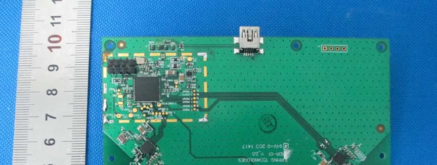
Dongguan Dongdian Testing Service Co., Ltd Report No: DDT-REF140345 Page 216 of 222 Dongguan Dongdian Testing Service Co., Ltd Report No: DDT-REF140345 Page 217 of 222 Dongguan Dongdian Testing Service Co., Ltd Report No: DDT-REF140345 Page 218 of 222 Dongguan Dongdian Testing Service Co., Ltd Report No: DDT-REF140345 Page 219 of 222 Dongguan Dongdian Testing Service Co., Ltd Report No: DDT-REF140345 Page 220 of 222 Dongguan Dongdian Testing Service Co., Ltd Report No: DDT-REF140345 Page 221 of 222 Dongguan Dongdian Testing Service Co., Ltd Report No: DDT-REF140345 Page 222 of 222 END OF REPORT
RF Exposure Info
RF Exposure Evaluation Result 1. Requirement Systems operating under the provisions of FCC 47 CFR section shall be operated in a manner that ensures that the public is not exposed to radio frequency energy level in excess of the Commission’s guidelines. In accordance with 47 CFR FCC Part 2 Subpart J, section 2.1091 this device has been defined as mobile device whereby a distance of 0.2m normally can be maintained between the user and the device, and below RF Permissible Exposure limit shall comply with. In accordance with KDB447498D01 for Simultaneous transmission MPE test exclusion applies when the sum of the MPE ratios for all simultaneous transmitting antennas incorporated in a host device, based on the calculated/estimated, numerically modeled or measured field strengths or power density, is ≤ 1.0. The MPE ratio of each antenna is determined at the minimum test separation distance required by the operating configurations and exposure conditions of the host device, according to the ratio of field strengths or power density to MPE limit, at the test frequency. Either the maximum peak or spatially averaged results from measurements or numerical simulations may be used to determine the MPE ratios. Spatial averaging does not apply when MPE is estimated using simple calculations based on far-field plane-wave equivalent conditions. The antenna installation and operating requirements for the host device must meet the minimum test separation distances required by all antennas, in both standalone and simultaneous transmission operations, to satisfy compliance. Limits for General Population/Uncontrolled Exposure 2. Calculation Method Predication of MPE limit at a given distance Equation from page 18 of OET Bulletin 65, Edition 97-01 S=PG/4πR² Where: S=power density P=power input to antenna G=power gain of the antenna in the direction of interest relative to an isotropic radiator R=distance to the center of radiation of the antenna From the peak EUT RF output power, the minimum mobile separation distance, d=0.2m, as well as the gain of the used antenna, the RF power density can be obtained. 3. Estimation Result 3.1 Manufacturing tolerance 802.11b (Average) Antenna Antenna 1 Antenna 2 Antenna 3 Antenna 4 Channel 1 6 11 1 6 11 1 6 11 1 6 11 Target (dBm) 15.00 15.00 15.00 15.00 15.00 15.00 15.00 15.00 15.00 15.00 15.00 15.00 Tolerance ±(dB) 1.00 1.00 1.00 1.001.001.001.001.001.00 1.00 1.001.00 802.11g (Average) Antenna Antenna 1 Antenna 2 Antenna 3 Antenna 4 Channel 1 6 11 1 6 11 1 6 11 1 6 11 Target (dBm) 10.00 10.00 10.00 10.00 10.00 10.00 10.00 10.00 10.00 10.00 10.00 10.00 Tolerance ±(dB) 1.00 1.00 1.00 1.001.001.001.001.001.00 1.00 1.001.00 802.11n HT20 (Average) Antenna Antenna 1 Antenna 2 Antenna 3 Antenna 4 Channel 1 6 11 1 6 11 1 6 11 1 6 11 Target (dBm) 12.00 12.00 12.00 12.00 12.00 12.00 12.00 12.00 12.00 12.00 12.00 12.00 Tolerance ±(dB) 1.00 1.00 1.00 1.001.001.001.001.001.00 1.00 1.001.00 802.11n HT40 (Average) Antenna Antenna 1 Antenna 2 Antenna 3 Antenna 4 Channel 3 6 9 3 6 9 3 6 9 3 6 9 Target (dBm) 12.00 12.00 12.00 12.00 12.00 12.00 12.00 12.00 12.00 12.00 12.00 12.00 Tolerance ±(dB) 1.00 1.00 1.00 1.001.001.001.001.001.00 1.00 1.001.00 3.2 Measurement Results Mode Frequency (MHz) Output power (Including tune-up tolerance) (dBm) Output power (mW) Antenna Gain (dBi) Antenna Gain (linear) MPE ratios (mW/cm 2 ) Antenna 1 2412 16.00 39.811 2.7 1.86 0.0148 2442 16.00 39.811 2.7 1.86 0.0148 11b 2462 16.00 39.811 2.7 1.86 0.0148 2412 11.00 12.589 2.7 1.86 0.0047 2442 11.00 12.589 2.7 1.86 0.0047 11g 2462 11.00 12.589 2.7 1.86 0.0047 2412 13.00 19.523 2.7 1.86 0.0074 2442 13.00 19.523 2.7 1.86 0.0074 11n HT 20 2462 13.00 19.523 2.7 1.86 0.0074 2422 13.00 19.523 2.7 1.86 0.0074 2442 13.00 19.523 2.7 1.86 0.0074 11n HT40 2452 13.00 19.523 2.7 1.86 0.0074 Antenna 2 2412 16.00 39.811 2.7 1.86 0.0148 2442 16.00 39.811 2.7 1.86 0.0148 11b 2462 16.00 39.811 2.7 1.86 0.0148 2412 11.00 12.589 2.7 1.86 0.0047 2442 11.00 12.589 2.7 1.86 0.0047 11g 2462 11.00 12.589 2.7 1.86 0.0047 2412 13.00 19.523 2.7 1.86 0.0074 2442 13.00 19.523 2.7 1.86 0.0074 11n HT 20 2462 13.00 19.523 2.7 1.86 0.0074 2422 13.00 19.523 2.7 1.86 0.0074 11n HT40 2442 13.00 19.523 2.7 1.86 0.0074 2452 13.00 19.523 2.7 1.86 0.0074 Antenna 3 2412 16.00 39.811 2.7 1.86 0.0148 2442 16.00 39.811 2.7 1.86 0.0148 11b 2462 16.00 39.811 2.7 1.86 0.0148 2412 11.00 12.589 2.7 1.86 0.0047 2442 11.00 12.589 2.7 1.86 0.0047 11g 2462 11.00 12.589 2.7 1.86 0.0047 2412 13.00 19.523 2.7 1.86 0.0074 2442 13.00 19.523 2.7 1.86 0.0074 11n HT 20 2462 13.00 19.523 2.7 1.86 0.0074 2422 13.00 19.523 2.7 1.86 0.0074 2442 13.00 19.523 2.7 1.86 0.0074 11n HT40 2452 13.00 19.523 2.7 1.86 0.0074 Antenna 4 2412 16.00 39.811 2.7 1.86 0.0148 2442 16.00 39.811 2.7 1.86 0.0148 11b 2462 16.00 39.811 2.7 1.86 0.0148 2412 11.00 12.589 2.7 1.86 0.0047 2442 11.00 12.589 2.7 1.86 0.0047 11g 2462 11.00 12.589 2.7 1.86 0.0047 2412 13.00 19.523 2.7 1.86 0.0074 2442 13.00 19.523 2.7 1.86 0.0074 11n HT 20 2462 13.00 19.523 2.7 1.86 0.0074 2422 13.00 19.523 2.7 1.86 0.0074 2442 13.00 19.523 2.7 1.86 0.0074 11n HT40 2452 13.00 19.523 2.7 1.86 0.0074 According to KDB447498 for Transmitters used in mobile exposure conditions for simultaneous transmission operations; ∑ of MPE ratios ≤ 1.0 Mode Frequency (MHz) ∑ MPE ratios (mW/cm 2 ) Limit Results 1 Antenna 2412 0.0148 1.000 Pass 2442 0.0148 1.000 Pass 11b 2462 0.0148 1.000 Pass 2412 0.0047 1.000 Pass 2442 0.0047 1.000 Pass 11g 2462 0.0047 1.000 Pass 2412 0.0074 1.000 Pass 11n HT 20 2442 0.0074 1.000 Pass 2462 0.0074 1.000 Pass 2422 0.0074 1.000 Pass 2442 0.0074 1.000 Pass 11n HT40 2452 0.0074 1.000 Pass 2 Antennas 2412 0.0296 1.000 Pass 2442 0.0296 1.000 Pass 11b 2462 0.0296 1.000 Pass 2412 0.0094 1.000 Pass 2442 0.0094 1.000 Pass 11g 2462 0.0094 1.000 Pass 2412 0.0148 1.000 Pass 2442 0.0148 1.000 Pass 11n HT 20 2462 0.0148 1.000 Pass 2422 0.0148 1.000 Pass 2442 0.0148 1.000 Pass 11n HT40 2452 0.0148 1.000 Pass 3 Antennas 2412 0…
Text truncated - open the document above for the full version.
Test Report
Dongguan Dongdian Testing Service Co., Ltd Report No:DDT-REF140345 Page 1 of 222 FCC AND IC CERTIFICATION TEST REPORT FOR Issued By: Dongguan Dongdian Testing Service Co., Ltd. Add: No. 17, Zongbu Road 2, Songshan Lake Sci&Tech, Industry Park, Dongguan City, Guangdong Province, China, 523808 Tel: +86-0769-22891499 Http://www.dgddt.com Applicant : Turning Technologies, LLC Address : 255 W. Federal Street Youngstown, OH 44503 Equipment under Test : Turning Model No : RRAP-01 Trade Mark : / FCC ID : R4WRRAP01 IC : 5994A-RRAP01 Manufacturer : Globalscale Technologies Inc Address : 5F.No.2 Building, Minxing lndustrial Park, Minkang Road, Minzhi Street, Baoan District, Shenzhen, Guangdong, China Report No: DDT-REF140345 Issued Date: Mar.16,2015 Dongguan Dongdian Testing Service Co., Ltd Report No:DDT-REF140345 Page 2 of 222 TABLE OF CONTENTS Test report declares......................................................................................................................4 1. Summary of test results ............................................................................................................... 5 2. General test information .............................................................................................................. 6 2.1. Description of EUT ..................................................................................................................... 6 2.2. Accessories of EUT..................................................................................................................... 6 2.3. Assistant equipment used for test ................................................................................................ 6 2.4. Block diagram of EUT configuration for test ............................................................................. 6 2.5. Test environment conditions ....................................................................................................... 7 2.6. Test laboratory............................................................................................................................. 7 2.7. Measurement uncertainty ............................................................................................................ 7 3. 6dB Bandwidth and 99% Bandwidth .......................................................................................... 9 3.1. Test equipment ............................................................................................................................ 9 3.2. Block diagram of test setup ......................................................................................................... 9 3.3. Limits .......................................................................................................................................... 9 3.4. Test Procedure............................................................................................................................. 9 3.5. 6dB Bandwidth Test Result......................................................................................................... 9 3.6. 99% Bandwidth Test Result ...................................................................................................... 10 4. Maximum Peak Output Power .................................................................................................. 12 4.1. Test equipment .......................................................................................................................... 12 4.2. Block diagram of test setup ....................................................................................................... 12 4.3. Limits ........................................................................................................................................ 12 4.4. Test Procedure........................................................................................................................... 12 4.5. Test Result................................................................................................................................. 12 5. Power Spectral Density ............................................................................................................. 14 5.1. Test equipment .......................................................................................................................... 14 5.2. Block diagram of test setup ....................................................................................................... 14 5.3. Limits ........................................................................................................................................ 14 5.4. Test Procedure........................................................................................................................... 14 5.5. Test Result................................................................................................................................. 14 6. Emissions outside the specified frequency bands ..................................................................... 16 6.1. Test equipment .......................................................................................................................... 16 6.2. Block diagram of test setup ....................................................................................................... 16 6.3. Limits ........................................................................................................................................ 16 6.4. Test Procedure........................................................................................................................... 16 6.5. Test Result................................................................................................................................. 17 6.6. Original test data ....................................................................................................................... 19 Dongguan Dongdian …
Text truncated - open the document above for the full version.
Test Setup Photos
Dongguan Dongdian Testing Service Co., Ltd Report No: DDT-REF140345 Page 211 of 222 11. Test setup photograph
Contact Information
Applicant
Rob Kerber(Director of Operations)
Test Firm
Dongguan Dongdian Testing Service Co.,LtdJamy Yu
[email protected]086-0769-22891499
Technical Specifications
| # | Rule Parts | Frequency Range | Power Output |
|---|---|---|---|
| 2 | 15C | 2.42 GHz - 2.45 GHz | 326.00 mW |
Other Applications from Turning Technologies, LLC
R4WRRDR01
Mar 11, 20152.4GHz RF module
Equipment Class
DXX - Part 15 Low Power Communication Device Transmitter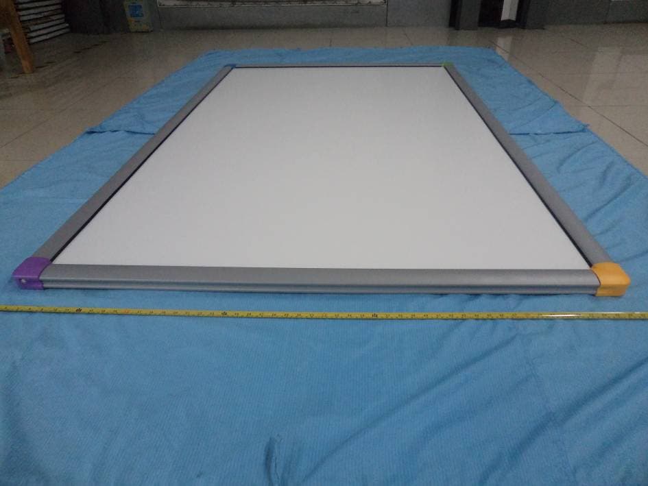
R4WTTTB10
Oct 26, 2014Touch Board Plus
Equipment Class
JBP - Part 15 Class B Computing Device Peripheral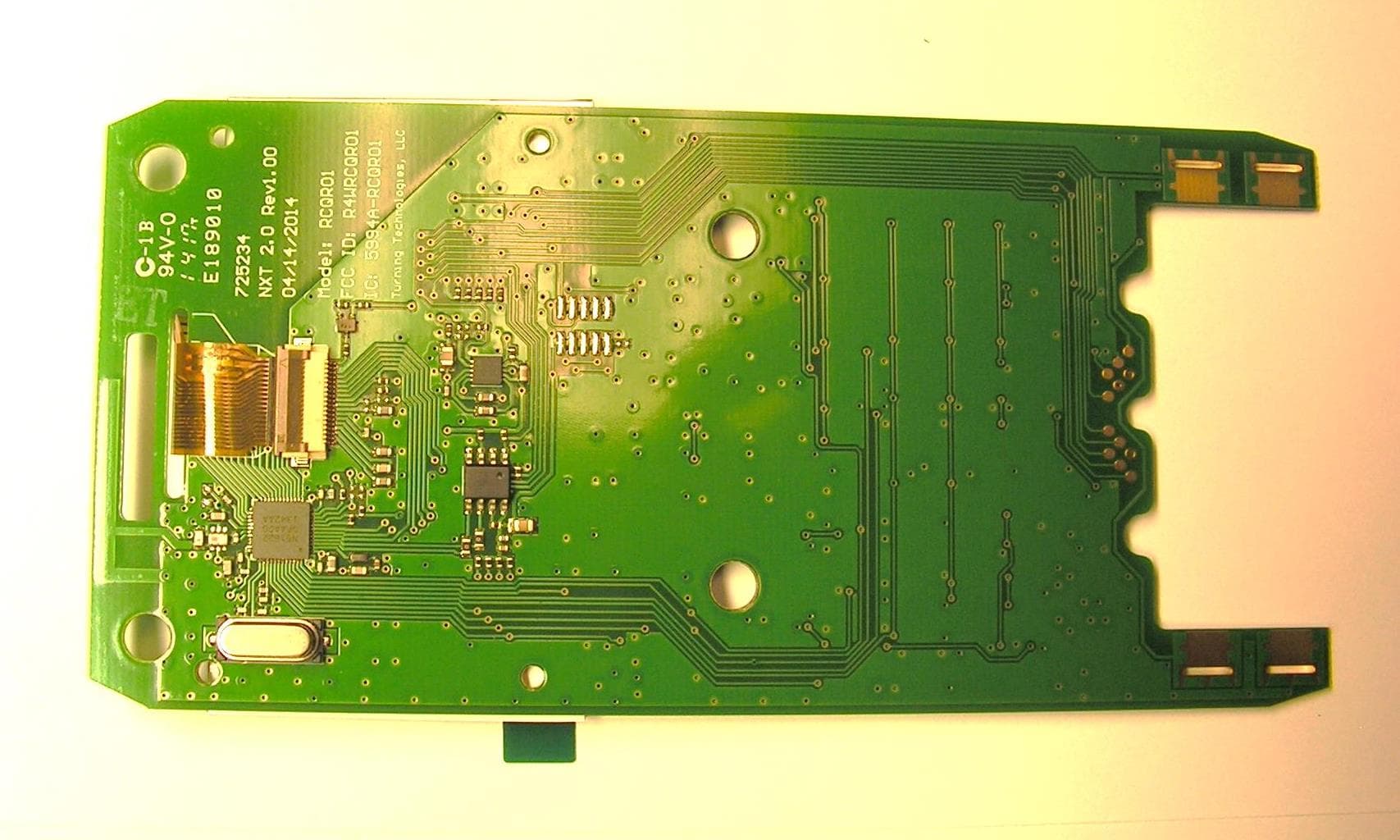
R4WRCQR01
May 05, 2014Low Power RF Module
Equipment Class
DXT - Part 15 Low Power Transceiver, Rx Verified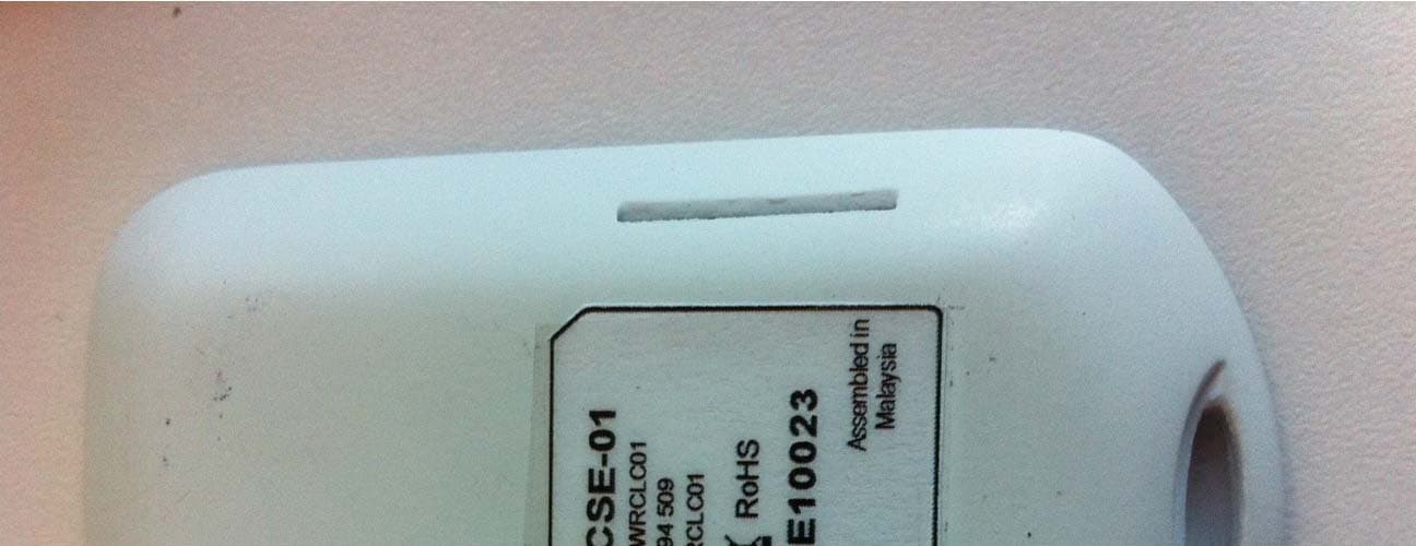
R4WRCLC01
Jul 14, 2013ResponseCard Single Event
Equipment Class
DXX - Part 15 Low Power Communication Device Transmitter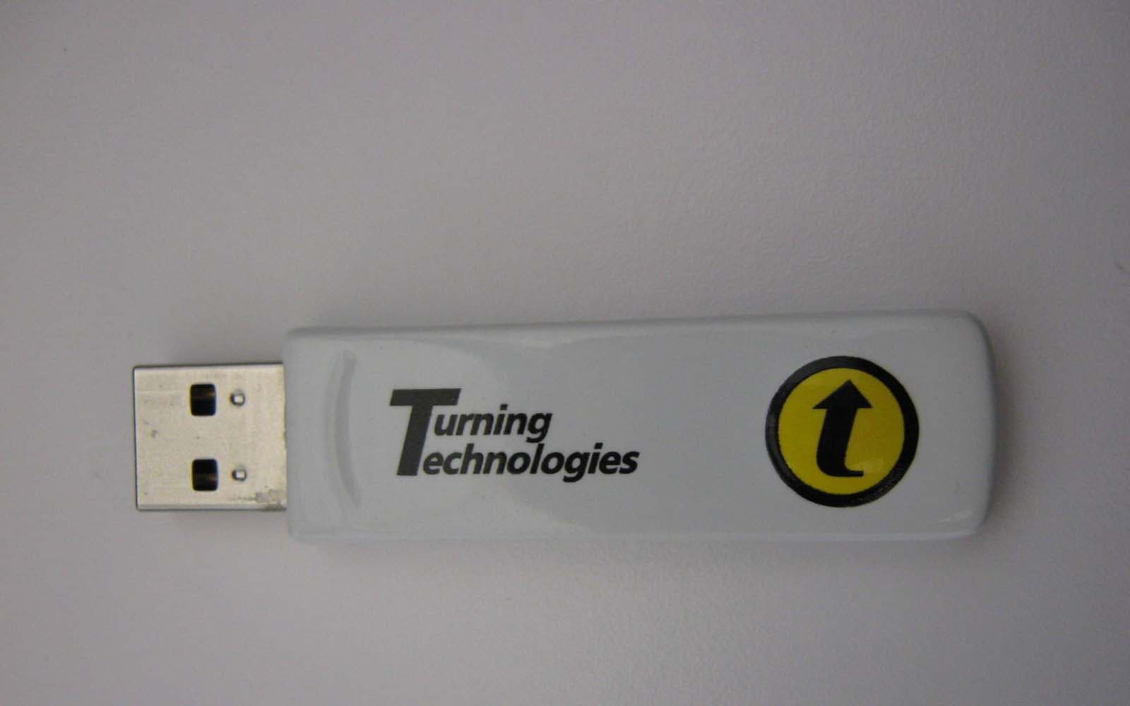
R4WRRRF04
Aug 06, 2012RF Receiver
Equipment Class
DXX - Part 15 Low Power Communication Device Transmitter