R4WRRRF04RF Receiver
Turning Technologies, LLC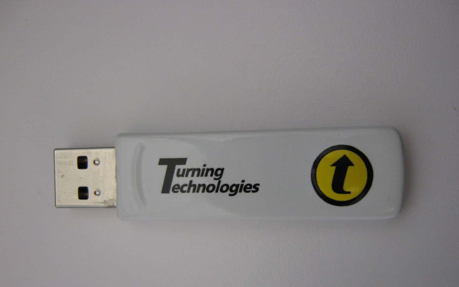
Click to zoom
Application Details
- Equipment Class
- DXX - Part 15 Low Power Communication Device Transmitter
- Date of Grant
- Aug 06, 2012
- Application Purpose
- Original Equipment
- Date of Application
- Aug 06, 2012
- Equipment Note
- RF Receiver
- Frequency Range
- 2401.00000000 - 2482.00000000
- Company
- Turning Technologies, LLC
- Country
- United States
Documents & Files
Document Text
Text extracted from the exhibit documents filed with the FCC. Open a document above to read the original.
Users Manual
Turning Technologies RCRF-03 ResponseCard RF LCD and RRRF-04 USB HID RF Receiver User’s Manual RCRF-03 & RRRF-04 User’s Manual Ver. Preliminary Overview: The RCRF-03 Keypad is designed to be used with the RRRF-04 Receiver connected to a PC. The keypad transmits key presses via radio frequency to the RF receiver for accumulation by the PC. The keypad consists of 12 data ke ys (0-9, Channel, ?), a single status LED, and a small LCD. ResponseCard RF LCD (RCRF-03) The ResponseCard RF LCD keypad is handheld designed to send responses over RF to a receiver. In Idle state, the LED and LCD are OFF. The keypad returns to idle state after comple tion of a key press. Standard Operation Mode: Initially the status LED and LCD are OFF. Pressing a single key will cause the key to be transmitted to the receiver. After pressing a key the status LED and LCD will display the status as follows: Quick Yellow Blink then OFF/ LCD with Circle with Slash - Receiver is not accepting data at this time Blinking Yellow - key is being transmitted (up to 8 seconds) Solid Green/LCD with Response pressed - key transmit successful - ready for input Solid Red/LCD with Ch and Slash - key transmit failed – ready for input Blinking Green/LCD with Response pressed - Receiver indicated correct answer Blinking Red - Receiver indicated incorrect answer Blinking Green and Blinking Red will only occur if the Receiver is configured to indicate a correct or incorrect answer (CORRECT POLLING mode). Set RF Channel Press Channel Button Set RF Channel mode is indicated by the status LED flashing a RED then GREEN pattern. Set RF Channel mode exits automatically after three valid keys are pressed, if no valid key is pressed for 8 seconds, or at any tim e an invalid key is pressed. Valid keys are ‘0’ through ‘9’. Valid RF Channels are ‘01’ through ‘82’. While in Set RF Channel mode pressing a valid key will cause the status LED to briefly flash YELLOW. When Set RF Channel Mode exits, the status LED i ndicates the result as follows: Solid Green - Set RF Channel successful Solid Red - Set RF Channel failed HID RF Receiver (RRRF-04) The RRRF-04 needs to be plugged into a USB port on a computer to ensure proper operation. Once the RRRF-04 is plugged in and recognized by the operating system, the appropriate software from Turning Technologies must be launched to enable the polling solution. REGULATORY INFORMATION FCC Statement This device complies with part 15 of the FCC Rules. Operation is subject to the following two conditions: (1) This device may not cause harmful interference, and (2 ) this device must accept any interference received, includi ng interference that may cause undesired operation. Canada Statement This device complies with Indus try Canada license-exempt RSS standard(s). Operation is subjec t to the following two conditions: (1) this device may not cause interf erence, and (2) this device must accept any interference, including interference that may cause undesired operation of the device. Le présent appareil est confor me aux CNR d'Industrie Canada applicables aux appareils radio ex empts de licence. L'exploitation est autorisée aux deux conditions su ivantes : (1) l'appareil ne doit pas produire de brouillage, et (2) l'utilisateur de l'appareil doit accepter tout brouillage radioélectrique subi, même si le brouillage est susceptible d'en compromettre le fonctionnement. This digital apparatus should not be connected to a PC with a USB cable exceeding 3 meters in length.
ID Label/Location Info
2 SCALE 1:1 P/N:RRRF-04 Device ID: 0512 00000000 Malaysia Patent info at ttpatents.com RoHS FCC ID : R4WRRRF04 ACN : 008 594 509 IC : 5994A-RRRF04 SCALE 1:1 Assembled in Red = Variable Data Image Placeholder
Test Report
Engineering Test Report No. 1201568-01 Measurement of RF Emissions from a RRRF-04 USB Dongle Transceiver For Turning Technologies, LLC. 255 W Federal Street Youngstown, OH 44503 P.O. Number 00000008225 Date Tested June 26 th through July 10, 2012 Test Personnel Richard E. King Test Specification FCC "Code of Federal Regulations” Title 47 Part15, Subpart C Industry Canada RSS-GEN Industry Canada RSS-210 Test Report By: Richard E. King EMC Engineer Requested By: Josh Blackann and Hugo Mendez Turning Technologies, LLC. Approved By: Raymond J. Klouda Registered Professional Engineer of Illinois - 44894 Elite Electronic Engineering, Inc. 1516 Centre Circle Downers Grove, IL 60515 Tel : (630) 495-9770 Fax: (630) 495-9785 www.elitetest.com Engineering Test Report No. 1201568-01 TABLE OF CONTENTS PARAGRAPH DESCRIPTION OF CONTENTS PAGE NO. THIS REPORT SHALL NOT BE REPRODUCED, EXCEPT IN FULL, WITHOUT THE WRITTEN APPROVAL OF ELITE ELECTRONIC ENGINEERING INCORPORATED. Page 2 of 62 1. Introduction ................................................................................................................................................... 4 1.1. Scope of Tests ..................................................................................................................................... 4 1.2. Purpose ............................................................................................................................................... 4 1.3. Deviations, Additions and Exclusions .................................................................................................. 4 1.4. EMC Laboratory Identification ............................................................................................................. 4 1.5. Laboratory Conditions.......................................................................................................................... 4 2. Applicable Documents .................................................................................................................................. 4 3. EUT Setup and Operation ............................................................................................................................ 4 3.1. General Description ............................................................................................................................. 4 3.1.1. Power Input ................................................................................................................................. 5 3.1.2. Peripheral Equipment ................................................................................................................. 5 3.1.3. Signal Input/Output Leads .......................................................................................................... 5 3.1.4. Grounding ................................................................................................................................... 5 3.2. Operational Mode ................................................................................................................................ 5 3.3. EUT Modifications ................................................................................................................................ 5 4. Test Facility and Test Instrumentation ......................................................................................................... 5 4.1. Shielded Enclosure .............................................................................................................................. 5 4.2. Test Instrumentation ............................................................................................................................ 5 4.3. Calibration Traceability ........................................................................................................................ 5 4.4. Measurement Uncertainty ................................................................................................................... 5 5. Test Procedures ........................................................................................................................................... 6 5.1. Powerline Conducted Emissions ......................................................................................................... 6 5.1.1. Requirements .............................................................................................................................. 6 5.1.2. Procedures .................................................................................................................................. 6 5.1.3. Results ........................................................................................................................................ 7 5.2. Duty Cycle Factor Measurements ....................................................................................................... 7 5.2.1. Procedures .................................................................................................................................. 7 5.2.2. Results ........................................................................................................................................ 7 5.3. Radiated Measurements ..................................................................................................................... 7 5.3.1. Requirements .............................................................................................................................. 7 5.3.2. Procedures .................................................................................................................................. 7 5.3.3. Results ........................................................................................................................................ 8 5.4. Bandedge Compliance ........................................................................................................................ 8 5.4.1. Requirement.......…
Text truncated - open the document above for the full version.
Test Setup Photos
Engineering Test Report No. 1201568-01 Page 14 of 62 Figure 2 Test Setup for Radiated Emissions, 30MHz to 1GHz – Horizontal Polarization Test Setup for Radiated Emissions, 30MHz to 1GHz – Vertical Polarization Engineering Test Report No. 1201568-01 Page 15 of 62 Figure 4 Test Setup for Radiated Emissions, above 1GHz – Horizontal Polarization Test Setup for Radiated Emissions, above 1GHz – Vertical Polarization
Contact Information
Applicant
Rob Kerber(Director of Operations)
Technical Contact
Turning Technologies, LLCJosh Blackann
[email protected]3305994917
255 W Federal St · Youngstown, Ohio · United States
Non-Technical Contact
Turning Technologies, LLCJosh Blackann
[email protected]3305994917
Test Firm
Elite Electronic Engineering Inc.Kevin Halpin
Technical Specifications
| # | Rule Parts | Frequency Range | Power Output |
|---|---|---|---|
| 1 | 15C | 2.40 GHz - 2.48 GHz | - |
Other Applications from Turning Technologies, LLC
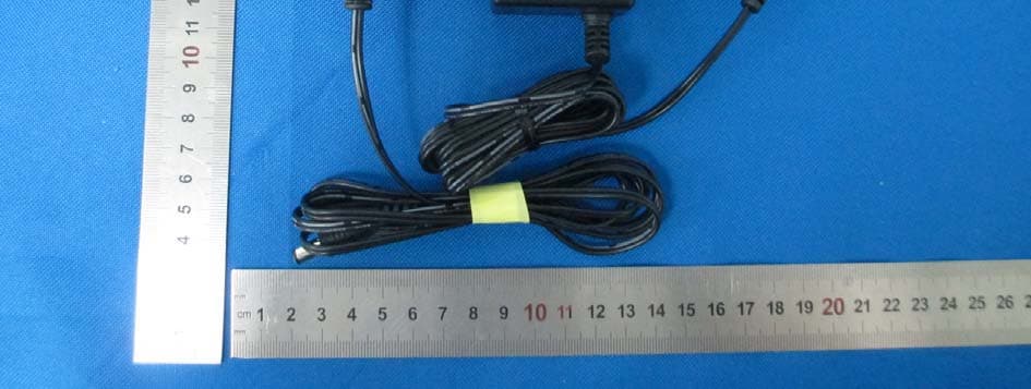
R4WRRAP01
Mar 23, 2015Turning
Equipment Class
DTS - Digital Transmission System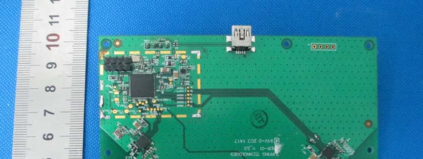
R4WRRDR01
Mar 11, 20152.4GHz RF module
Equipment Class
DXX - Part 15 Low Power Communication Device Transmitter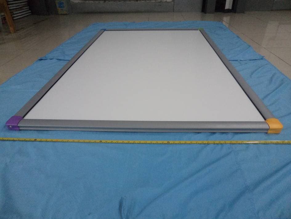
R4WTTTB10
Oct 26, 2014Touch Board Plus
Equipment Class
JBP - Part 15 Class B Computing Device Peripheral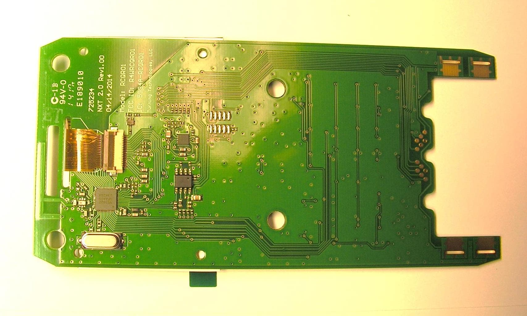
R4WRCQR01
May 05, 2014Low Power RF Module
Equipment Class
DXT - Part 15 Low Power Transceiver, Rx Verified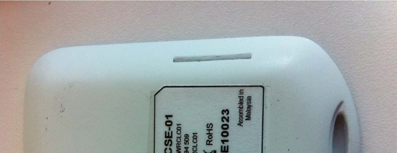
R4WRCLC01
Jul 14, 2013ResponseCard Single Event
Equipment Class
DXX - Part 15 Low Power Communication Device Transmitter