R4WRRUSB01Infrared Remote USB Receiver
Turning Technologies, LLC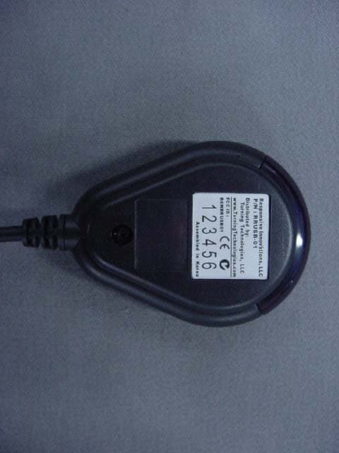
Click to zoom
Application Details
- Equipment Class
- JBP - Part 15 Class B Computing Device Peripheral
- Date of Grant
- Jul 05, 2005
- Application Purpose
- Original Equipment
- Date of Application
- Jul 05, 2005
- Equipment Note
- Infrared Remote USB Receiver
- Company
- Turning Technologies, LLC
- Country
- United States
Documents & Files
Document Text
Text extracted from the exhibit documents filed with the FCC. Open a document above to read the original.
Users Manual
< ResponseCard XL > 1. Introduction It is a part of educational system, students using this system can transmit answers though it to PC remotely. Then a receiving part accepts the signal form the each student and passes it over to a PC. Finally, the PC saves the answers and reconstructs them. 2. Remote Keypad It has a unique ID. It can be operated in the Presentation & Test mode. In case of Presentation Mode, once if the number key on the keypad is selected, it transmits the unique ID and corresponding IR signal. And regarding Test Mode, an user can store any answers in the remote keypad & the maximum stored data will be 999 and the stored answer will be transmitted to PC after downloading at IR USB Receiver. 2.1 General Features z There are two modes - Presentation mode and Test mode z LCD display - Question Number , Answer and so on z 15 buttons (0~9, *, ? ,↓(N), ↑(Y), T/P) z LED - Lights when button is pressed while in Presentation Mode - Lights when low battery voltage is detected z Two batteries – CR2450 (3V) x 2ea z Non-volatile memory (EEPROM) capable of storing up to 999 single digit responses 2.2 LCD display • 4 large digits ; 3 for Question Number and one for Answer When Presentation mode When Test mode • In Test mode, a dialog display to interface with user with feedback questions such as "Lease Test Mode? (Y/N)" and “Erase Stored Data? (Y/N)” 2.3 Buttons There are 15 buttons for education XL remote keypad. 2.4 ID code There are 6,291,456 possible ID combinations available. Range: A00000 ~ FFFFFF ID code is stored in a non-volatile EEPROM. Each keypad except ↓(N), ↑(Y), T/P have unique factory programmed System ID when the Presentation mode 2.5 Presentation mode While in "Presentation" mode, units LCD Display is completely blank, except when key is press and unit functions exactly like ResponseCard IR units. Any Transmission key (0~9, * and ?) should be “echoed” for three seconds in the ↓(N) ↑(Y) T/P 1/A 2/B 3/C 4/D 5/E 6/F 7/G 8/H 9/I * 0/J ? Answer field of the LCD. LCD display is blank when Normal status Echoed for 3 second when key is pressed 2.5.1 Setting ID ID of each remote can be set to a desired ID code as follows: a) Press and hold both “*” and “6” buttons until LED is lit constantly. b) Press the numeric key corresponding the desired ID code. For code “000123”, ‘0’, ‘0’, ‘0’, ‘1’, ‘2’, ‘3’ serially. c) IR remote will acknowledge by blinking LED 3 times. 2.5.2 Revert back to factory programmed ID ID of each remote can be reverted to an original factory programmed ID code as follows: a) Press and hold both “*” and “1” buttons until LED turns on constantly. b) IR remote will acknowledge by blinking LED 3 times. 2.6 Test mode When Mode button (T/P) is pressed, unit promptly to input control number. When 3 digits are input, unit enters "Test" mode. 2.6.1 Operation in Test mode • While in Test mode, no data is transferred via IR. • LCD displays “TEST” under Answer space. • LCD displays to show 001 Question and Blank Answer. • Student can use Up and Down Scroll buttons to change Question Number 001~999, enter and/or review answers already stored. • Student can change the wanted number by themselves through Goto function. a) Press ‘*’, then the first digit will be blink for Question Number. b) If press the wanted number, the next digit will be blink for Question Number. c) And press the wanted number, the next will be blink for Question Number of third digit. d) Press ‘?’. then stop to blink the digits and return to test mode. • When any answer is entered into the unit, the answer and corresponding question number are displayed for three seconds. After three seconds the Question number field is automatically incremented and the Answer field goes blank. The answer is displayed for 3 second when the answer is pressed After three seconds, the Question number field is automatically incremented • Answers and corresponding Question numbers are stored in EEPROM until deleted by user. • Students may return to Question numbers they have already answered or skipped, and change (i.e. enter new) answers. • Once student has completed test, Mode button (T/P) is pressed again. Unit displays "Leave Test Mode? (Y/N)" message. If "Y" is pressed, unit switches from Test mode to Locked mode and displays “LOCK” under Answer space. While in Lock mode, units Presentation capabilities are fully functional. • Unit may not leave Lock mode until stored answers are downloaded and previously stored answers are deleted. • Units are aimed at IR receiver and transmission/download is initiated by pressing the * and ? keys simultaneously. • Once Unit’s Test data is downloaded, Unit is permitted to re-enter Presentation mode or be downloaded again. • To re-enter Presentation mode, “T/P” button is pressed. User is asked “Erase Stored Data? (Y/N)”. • If Y is pressed, all stored data is deleted and unit re-enters Presentation mode. • If N is pressed unit remains in LOCK mode. 2.6.2 Method for transmission/download a) Units are aimed at IR receiver b) Press the “*” and “?” keys simultaneously c) When Transmit is started, unit transmits Unit ID, Control number, Number of Answers, Answers and End String via IR. Each transmission is send from answer of first question number (001) to last answer of maximum question number that have been input recently d) A LED flash as data is transmitted and goes out seconds when complete. 2.6.3 Power save mode while in Test mode a) LCD panel is displayed to blank if there is no button activity for 5 minutes while in Test mode. b) Any key press should wake unit up and the initially pressed key, which wakes the unit up, not be utilized in anyway. c) When leaving Power Save mode, unit return to exact place and state, prior to entering Power Save Mode 2.7 Range 2.7.1 Range while in Presentation mode The nominal IR transmission distance is 13m (~ 42’) when the battery is fresh. The IR transmission distance may reduce as the battery wears out. 2.7.2 Range while in Transmission/Download …
Text truncated - open the document above for the full version.
External Photos
FCC ID. : R4WRRUSB01 Report No.: E057R-002 ONETECH Testing & Evaluation Lab. FCC ID. : R4WRRUSB01 Report No.: E057R-002 ONETECH Testing & Evaluation Lab.
ID Label/Location Info
FCC ID. : R4WRRUSB01 Report No.: E057R-002 ONETECH Testing & Evaluation Lab. IDENTIFICATION LABEL: PROPOSED FCC ID LABEL Due to the product size, only the FCC ID shall be permanently affixed to the rear side of the equipment and other information shall be placed in the instruction manual. This device complies with Part 15 of the FCC Rules. Operation is subject to the following two conditions: (1) this device may not cause harmful interference, and (2) this device must accept any interference received, including interference that may cause undesired operations. Assembled in Korea FCC ID : R4WRRUSB01 FCC ID AREA
Internal Photos
FCC ID. : R4WRRUSB01 Report No.: E057R-002 ONETECH Testing & Evaluation Lab. FCC ID. : R4WRRUSB01 Report No.: E057R-002 ONETECH Testing & Evaluation Lab. FCC ID. : R4WRRUSB01 Report No.: E057R-002 ONETECH Testing & Evaluation Lab.
Test Report
Page 1 of 11 FCC ID. : R4WRRUSB01 Report No. : E057R-002 It should not be reproduced except in full, without the written approval of ONETECH. EMC-003 (Rev.0) HEAD OFFICE : #505 SK APT. Factory 223-28, Sangdaewon 1 Dong, Jungwon-Gu, Seongnam-City, Gyeonggi-Do, 462-705, Korea (TEL: +82-31-746-8500, FAX: +82-31-746-8700) EMC Department : 426-1 Daessangryung-Ri, Chowol-Eup, Kwangju-City, Kyeonggi-Do, 464-860, Korea. (TEL: +82-31-765-8289, FAX: +82-31-766-2904) ONETECH Testing & Evaluation Lab. ELECTROMAGNETIC EMISSION C OMPLIANCE REPORT FOR FCC CLASS B CERTIFICATION Test Report No. : E057R-002 Applicant : Responsive Innovations, LLC Address : 3789, Chesterfield Drive, Akron, OH 44319, United States Manufacturer : Seoby Electronics Co., Ltd. Address : #38-2, Anyang 2-Dong, Manan-Gu, Anyang-City, Kyungki-Do, Korea Type of Equipment : Infrared Remote USB Receiver FCC ID : R4WRRUSB01 Model Name : RRUSB-01 Serial Number : N/A Total page of Report : 11 pages (including this page) Date of Incoming : June 14, 2005 Date of Issuing : July 1, 2005 SUMMARY The equipment complies with the requirements of FCC CFR 47 PART 15 SUBPART B, Class B. This test report contains only the results of a single test of the sample supplied for the examination. It is not a general valid assessment of the features of the respective products of the mass-production. Prepared by: Reviewed by: Young-Min, Choi / Senior Engineer Y. K. Kwon / Director EMC Div. EMC Div. ONETECH Corp. ONETECH Corp. Page 2 of 11 FCC ID. : R4WRRUSB01 Report No. : E057R-002 It should not be reproduced except in full, without the written approval of ONETECH. EMC-003 (Rev.0) HEAD OFFICE : #505 SK APT. Factory 223-28, Sangdaewon 1 Dong, Jungwon-Gu, Seongnam-City, Gyeonggi-Do, 462-705, Korea (TEL: +82-31-746-8500, FAX: +82-31-746-8700) EMC Department : 426-1 Daessangryung-Ri, Chowol-Eup, Kwangju-City, Kyeonggi-Do, 464-860, Korea. (TEL: +82-31-765-8289, FAX: +82-31-766-2904) ONETECH Testing & Evaluation Lab. CONTENTS Page 1. VERIFICATION OF COMPLIANCE .............................................................................................................................3 2. GENERAL INFORMATION............................................................................................................................................4 2.1 PRODUCT DESCRIPTION.................................................................................................................................................4 2.2 MODEL DIFFERENCES:..................................................................................................................................................4 2.3 RELATED SUBMITTAL(S) / GRANT(S)............................................................................................................................4 2.4 TEST SYSTEM DETAILS..................................................................................................................................................4 2.5 TEST METHODOLOGY....................................................................................................................................................4 2.6 TEST FACILITY...............................................................................................................................................................5 3. SYSTEM TEST CONFIGURATION...............................................................................................................................5 3.1 JUSTIFICATION...............................................................................................................................................................5 3.2 EUT EXERCISE SOFTWARE............................................................................................................................................5 3.3 CABLE DESCRIPTION.....................................................................................................................................................5 3.4 NOISE SUPPRESSION PARTS ON CABLE.........................................................................................................................6 3.5 EQUIPMENT MODIFICATIONS........................................................................................................................................6 3.6 CONFIGURATION OF TEST SYSTEM...............................................................................................................................6 4. PRELIMINARY TEST ......................................................................................................................................................6 4.1 AC POWER LINE CONDUCTED EMISSION TEST............................................................................................................6 4.2 RADIATED EMISSION TEST............................................................................................................................................6 5. FINAL RESULT OF MEASURMENT ............................................................................................................................7 5.1 CONDUCTED EMISSION TEST.........................................................................................................................................7 5.2 RADIATED EMISSION TEST............................................................................................................................................9 6. FIELD STRENGTH CALCULATION ............................................................................................................................9 7. LIST OF TEST EQUIPMENT........................................................................................................................................11 Page 3 of 11 FCC ID. : R4WRRUSB01 Report No. : E057R-002 It should not be reproduced except in full, without the written approval of ONETECH. EMC-003 (Rev.0) HEAD OFFICE : #505 SK APT. Factory 223-28, Sangdaewo…
Text truncated - open the document above for the full version.
Test Setup Photos
FCC ID. : R4WRRUSB01 Report No.: E057R-002 ONETECH Testing & Evaluation Lab. FCC ID. : R4WRRUSB01 Report No.: E057R-002 ONETECH Testing & Evaluation Lab.
Contact Information
Applicant
Rob Kerber(Director of Operations)
Test Firm
ONETECH Corp.Gea-Won Lee
Technical Specifications
| # | Rule Parts | Frequency Range | Power Output |
|---|---|---|---|
| 1 | 15B | - | - |
Other Applications from Turning Technologies, LLC
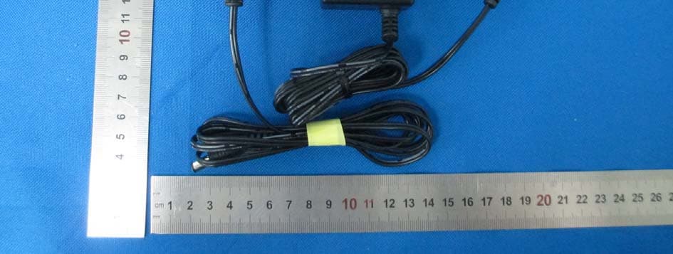
R4WRRAP01
Mar 23, 2015Turning
Equipment Class
DTS - Digital Transmission System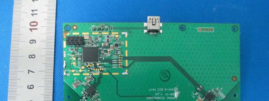
R4WRRDR01
Mar 11, 20152.4GHz RF module
Equipment Class
DXX - Part 15 Low Power Communication Device Transmitter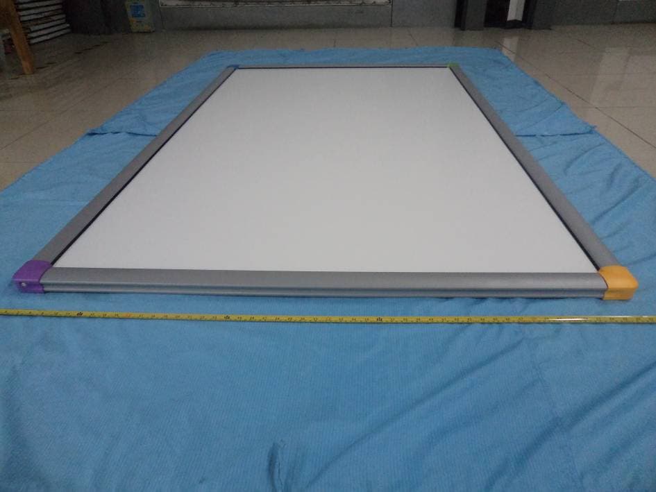
R4WTTTB10
Oct 26, 2014Touch Board Plus
Equipment Class
JBP - Part 15 Class B Computing Device Peripheral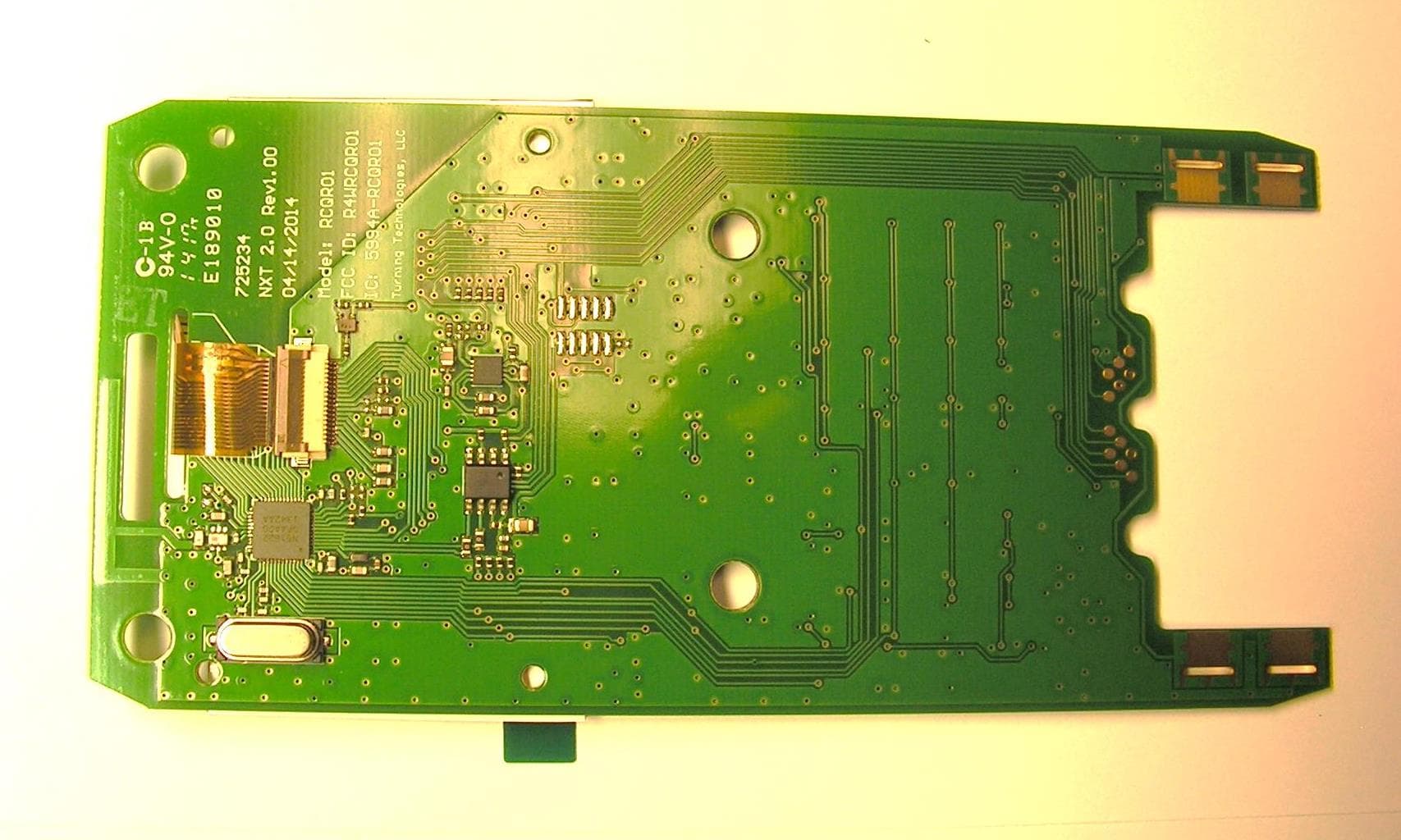
R4WRCQR01
May 05, 2014Low Power RF Module
Equipment Class
DXT - Part 15 Low Power Transceiver, Rx Verified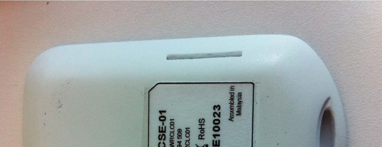
R4WRCLC01
Jul 14, 2013ResponseCard Single Event
Equipment Class
DXX - Part 15 Low Power Communication Device Transmitter