R55KSS91042-Way FRS Radio
Kids Station Toys Incorporated
Click to zoom
Application Details
- Equipment Class
- FRF - Part 95 Family Radio Face Held Transmitter
- Date of Grant
- May 24, 2006
- Application Purpose
- Original Equipment
- Date of Application
- May 24, 2006
- Equipment Note
- 2-Way FRS Radio
- Frequency Range
- 462.56250000 - 467.71250000
- Country
- Hong Kong
Documents & Files
Document Text
Text extracted from the exhibit documents filed with the FCC. Open a document above to read the original.
Users Manual
SPIDER-MAN 2- WAY FR S COMMUNICATOR S OWNER’S MANUAL Model: KSS9104 PLEASE READ BEFORE OPERATING THIS EQUIPMENT. KSS9104-IB-E00Q1-A0US.QXD 4/12/06 6:58 PM Page 1 1 SAFETY PRECAUTIONS Safety and General Information Exposure to Radio Frequency Energy Your radio is designed to comply with the following national and international standards and guidelines regarding exposure of human beings to radio frequency electromagnetic energy: •United States Federal Communications Commission, Code of Federal Regulations; 47 CFR part 2 sub-part J •American National Standards Institute (ANSI)/Institute of Electrical and Electronic Engineers (IEEE) C95.1-1992 •Institute of Electrical and Electronic Engineers (IEEE) C95.1-1999 Edition Safety and General Information 4 •International Commission on Non-Ionizing Radiation Protection (ICNIRP) 1998 •Ministry of Health (Canada) Safety Code 6. Limits of Human Exposure to Radio Frequency Electromagnetic Fields in the Frequency Range from 3 kHz to 300GHz, 1999 •Australian Communications Authority Radiocommunications (Electromagnetic Radiation–Human Exposure) Standard 2001 (applicable to wireless phones only) •ANATEL, Brazil Regulatory Authority, Resolution 256 (April 11, 2002) “additional requirements for SMR, cellular, and PCS product certification.” To assure optimal radio performance and make sure human exposure to radio frequency electromagnetic energy is within the guidelines set forth in the above standards, always adhere to the following procedures. Portable Radio Operation and EME Exposure Antenna Care Use only the supplied or an approved replacement antenna. Unauthorized antennas, modifications or attachments could damage the radio and may violate FCC regulations. DO NOT hold the antenna when the radio is “IN USE.” Holding the antenna affects the effective range. Two-Way Radio Operation When using your radio as a traditional two-way radio, hold the radio in a vertical position with the microphone 2 to 3 inches away from the lips. 2 Electromagnetic Interference/Compatibility NOTE : Nearly every electronic device is susceptible to electromagnetic interference (EMI) if inadequately shielded, designed or otherwise configured for electromagnetic compatibility . Facilitie s To avoid electromagnetic interference and/or compatibility conflicts, turn off your radio in any facility where posted notices instruct you to do so. Hospitals or health care facilities may be using equipment that is sensitive to external RF energy . Aircraf t When instructed to do so, turn off your radio when on board an aircraft. Any use of a radio must be in accordance with applicable regulations per airline crew instructions . Medical Device s Pacemaker s The Advanced Medical Technology Association recommends that a minimum separation of 6 inches (15 centimeters) be maintained between a handheld wireless radio and a pacemaker. These recommendations are consistent with the independent research by, and recommendations of, the U.S. Food and Drug Administration . Persons with pacemakers should : • ALWAYS keep the radio more than six inches (15 centimeters) from their pacemaker when the radio is turned ON . • not carry the radio in the breast pocket. • use the ear opposite the pacemaker to minimize the potential for interference. • turn the radio OFF immediately if you have any reason to suspect that interference is taking place . SAFETY PRECAUTIONS EXERCISE CAUTION AS UNIT HAS SHARP POINTS. LOCATION OF CONTROLS 3 8 7 9 10 1114 15 16 17 12 13 1 2 3 4 5 6 1. Antenna 2. TALK Button 3. CALL Button 4. DOWN Button 6. Speaker 5.Microphone 7. Display 8. MENU Button 9. POWER Button 10 . UP Button 11 . Scan 12 . Battery Level 13 . Transmit 14 . Lock 15 . Volume Level 16 . Channel Number 17 . Receive UNIT DISPLAY INSTALLATION 4 BATTERY PRECAUTIONS Follow these precautions when using batteries in this device: 1. Use only the size and type of batteries specified. 2. Be sure to follow the correct polarity when installing the batteries as indicated in the battery compartment. Reversed batteries may cause damage to the device. 3. Do not mix different types of batteries together (e.g. Alkaline, rechargeable and Carbon-zinc) or old batteries with fresh ones. 4. If the device is not to be used for a long period of time, remove the batteries to prevent damage or injury from possible battery leakage. 5. Do not try to recharge batteries not intended to be recharged; they can overheat 6. Do not try dispose of batteries in fire,batteries may explode or leak. and rupture. (Follow battery manufacturer’s directions.) Remove the screw, then lift off the battery cover . 1 Insert three (3) AAA batteries as shown by the polarity diagram in the compartment. Replace the battery cover . 2 REPLACING THE BATTERIES OPERATION (CONTINUED) 5 Transmitting range The talk range depends on the environment and terrain. It will be the greatest (up to about 2 miles) in wide open spaces, without obstructions such as hills or buildings. Don't try to use two radios which are less than 1.5m (5 feet) apart as you will get interference. Important Safety Warning •To reduce radio frequency exposure when you're using this radio, hold the handset at least 5cm (2 inches) from your face. •Never use the radio outdoors in a thunderstorm. •Don't use the radio in the rain. •If your radio gets wet, turn it off and remove the battery. Dry the battery compartment and leave the cover off for few hours. Don't use the radio until it is completely dry. •Keep the radio out of the reach of babies and young children. To turn on, press and hold the POWE R button until the channel displa y comes on. 1 To turn off, press and hold the POWE R button until the channel displa y turns off and a chime is heard. 2 TURNINGTHERADIO ON OR OFF 1 2 3 6 OPERATION (CONTINUED) Press the MENU button; th e current channel number will blin k in the display. 1 Press the UP or DOWN button to select the desired channel number. Press the TAL K button to confirm. 2 CHANGING THE CHANNELS This …
Text truncated - open the document above for the full version.
External Photos
APPENDIX C - EUT PHOTOGRAPHS EUT-Front View EUT-Rear View Kids Station Toys International Ltd. FCC ID: R55KSS9104 EUT-Battery-off View
ID Label/Location Info
APPENDIX A - FCC ID LABELING AND LOCATION Proposed FCC ID Labeling Proposed FCC ID Location Label Location Labeling Requirement Each equipment for which a type acceptance applications is filed on or after May 1, 1981, shall bear an identification plate or label pursuant to §2.295 (Identification of Equipment) and §2.926 (FCC identifier) In August 1996 the Federal Communications Commissions (FCC) adopted RF exposure guidelines with safety levels for hand-held wireless devices. Generally users manual contains a RF exposure statement to indicate compliance with FCC requirements. The users manual should also contain required information and instruction pursuant to 95.653. FCC ID: R55KSS9104
Internal Photos
EUT-Cover-off View EUT-Component View (1) Kids Station Toys International Ltd. FCC ID: R55KSS9104 Report # R0604287 FCC Part 95 Test Report Page 2 of 31 EUT-Component View (2) END OF REPORT
Test Report
FCC PART 95 EMI MEASUREMENT AND TEST REPORT For Kids Station Toys International Ltd. Room 804, 8/F, Empire Centre,68 Mody Road, Tsimshatsui East, Kowloon, Hong Kong FCC ID: R55KSS9104 Model: KSS9104 This Report Concerns: Original Report Product Type: Two Way FRS Radio Test Engineer: Daniel Deng Report Number: R0604287 Report Date: 2006-05-15 Reviewed By: James Ma Prepared By: Bay Area Compliance Laboratory Corporation 1274 Anvilwood Ave. Sunnyvale, CA 94089 Tel: (408) 732-9162 Fax: (408) 732 9164 TABLE OF CONTENTS GENERAL INFORMATION.......................................................................................................................................3 PRODUCT DESCRIPTION FOR EQUIPMENT UNDER TEST (EUT) ....................................................................................3 EUT PHOTO.................................................................................................................................................................3 OBJECTIVE...................................................................................................................................................................3 RELATED GRANT/SUBMISSION....................................................................................................................................3 TEST METHODOLOGY..................................................................................................................................................3 TEST FACILITY.............................................................................................................................................................4 SYSTEM TEST CONFIGURATION..........................................................................................................................5 JUSTIFICATION.............................................................................................................................................................5 SPECIAL ACCESSORIES.................................................................................................................................................5 EQUIPMENT MODIFICATIONS.......................................................................................................................................5 TEST SETUP BLOCK DIAGRAM.....................................................................................................................................5 REQUIREMENTS OF PROVISIONS ........................................................................................................................6 §2.1046 AND § 95.639 (D) – OUTPUT POWER ........................................................................................................7 APPLICABLE STANDARD..............................................................................................................................................7 TEST PROCEDURE........................................................................................................................................................7 TEST EQUIPMENT.........................................................................................................................................................7 ENVIRONMENTAL CONDITIONS....................................................................................................................................7 TEST RESULTS: ............................................................................................................................................................7 §2.1047, § 95.637(A) – MODULATION CHARACTERISTICS.............................................................................10 APPLICABLE STANDARD............................................................................................................................................10 TEST PROCEDURE......................................................................................................................................................10 TEST EQUIPMENT.......................................................................................................................................................10 ENVIRONMENTAL CONDITIONS..................................................................................................................................11 TEST RESULTS...........................................................................................................................................................11 §2.1049 AND § 95.633(C) - AUTHORIZED BANDWIDTH OF EMISSIONS......................................................13 APPLICABLE STANDARD............................................................................................................................................13 TEST PROCEDURE......................................................................................................................................................13 TEST EQUIPMENT.......................................................................................................................................................13 ENVIRONMENTAL CONDITIONS..................................................................................................................................13 TEST RESULTS...........................................................................................................................................................13 §2.1053, §95.635(B) UNWANTED RADIATION .....................................................................................................16 APPLICABLE STANDARD............................................................................................................................................16 TEST PROCEDURE......................................................................................................................................................16 TEST EQUIPMENT.....................................…
Text truncated - open the document above for the full version.
Contact Information
Applicant
Miss Kathy Lee(Executive Director)
Test Firm
Bay Area Compliance LaboratoryJohn Chan
Technical Specifications
| # | Rule Parts | Frequency Range | Power Output | Emission | Tolerance |
|---|---|---|---|---|---|
| 1 | 95B | 462.5625 MHz - 467.7125 MHz | 63.00 mW | 12K5F3E | 0.0002500000 % |
Other Applications from Kids Station Toys Incorporated

R55-KSD5071
Aug 29, 2013Wifi Tablet
Equipment Class
DTS - Digital Transmission System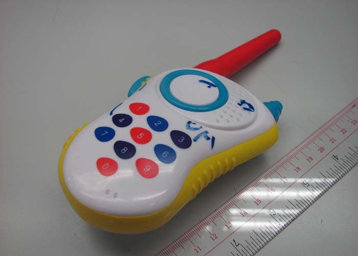
R55KS3159
Jun 01, 2012Handheld Walkie Talkies
Equipment Class
DXT - Part 15 Low Power Transceiver, Rx Verified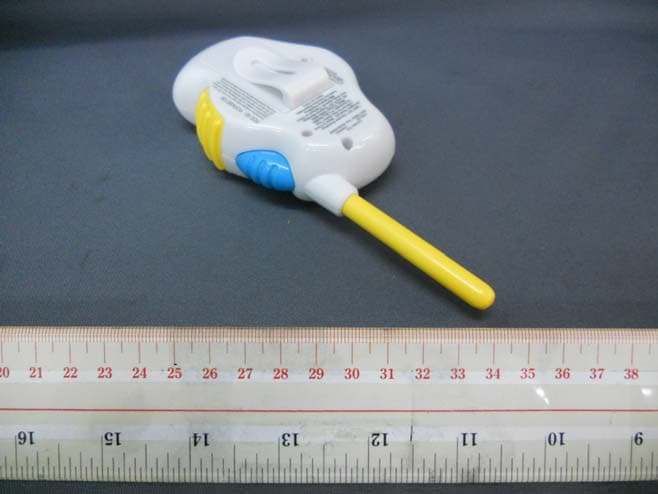
R55KSE120A
Jul 13, 2011Sesame Street Walkie Talkies
Equipment Class
DXX - Part 15 Low Power Communication Device Transmitter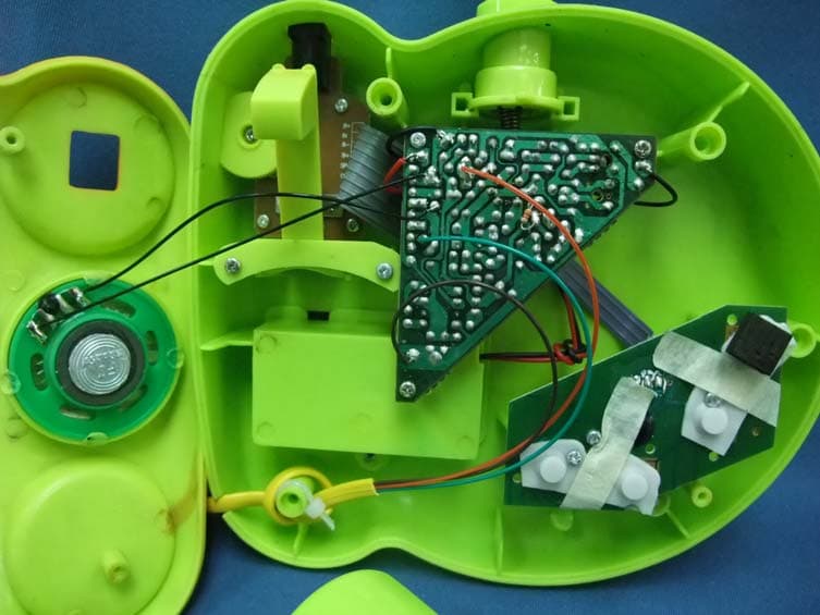
R55KS723
Aug 20, 2009Full duplex walkie talkie phone
Equipment Class
DXX - Part 15 Low Power Communication Device Transmitter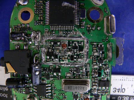
R55KSM6010
Mar 30, 20052 Way FRS & GMRS Micro-Wristband Communicators
Equipment Class
FRF - Part 95 Family Radio Face Held Transmitter