R68PENPremierWave EN Wireless Device Server
Lantronix, Inc.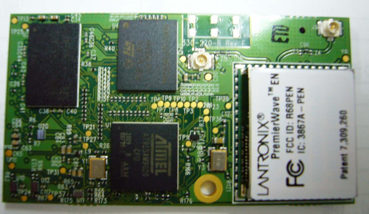
Click to zoom
Application Details
- Equipment Class
- NII - Unlicensed National Information Infrastructure TX
- Date of Grant
- Aug 16, 2011
- Application Purpose
- Original Equipment
- Date of Application
- Aug 15, 2011
- Equipment Note
- PremierWave EN Wireless Device Server
- Frequency Range
- 5500.00000000 - 5700.00000000
- Company
- Lantronix, Inc.
- Country
- United States
Documents & Files
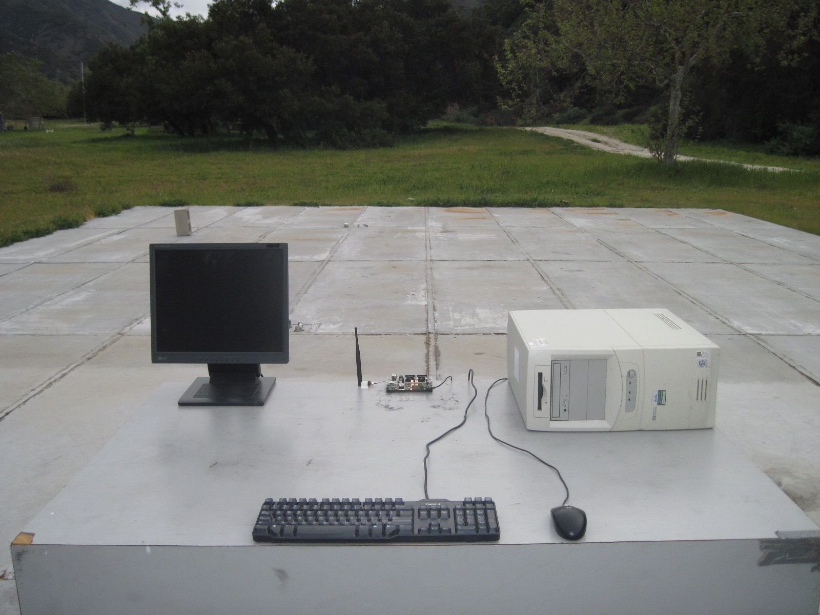
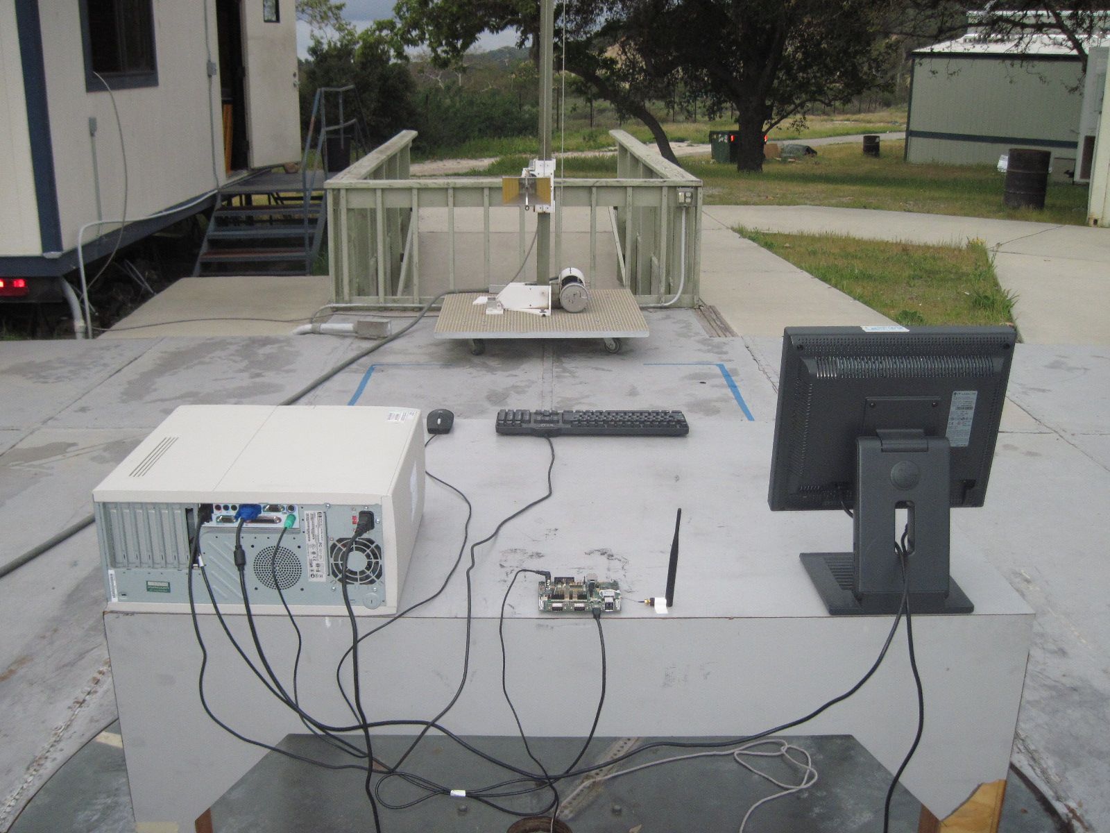
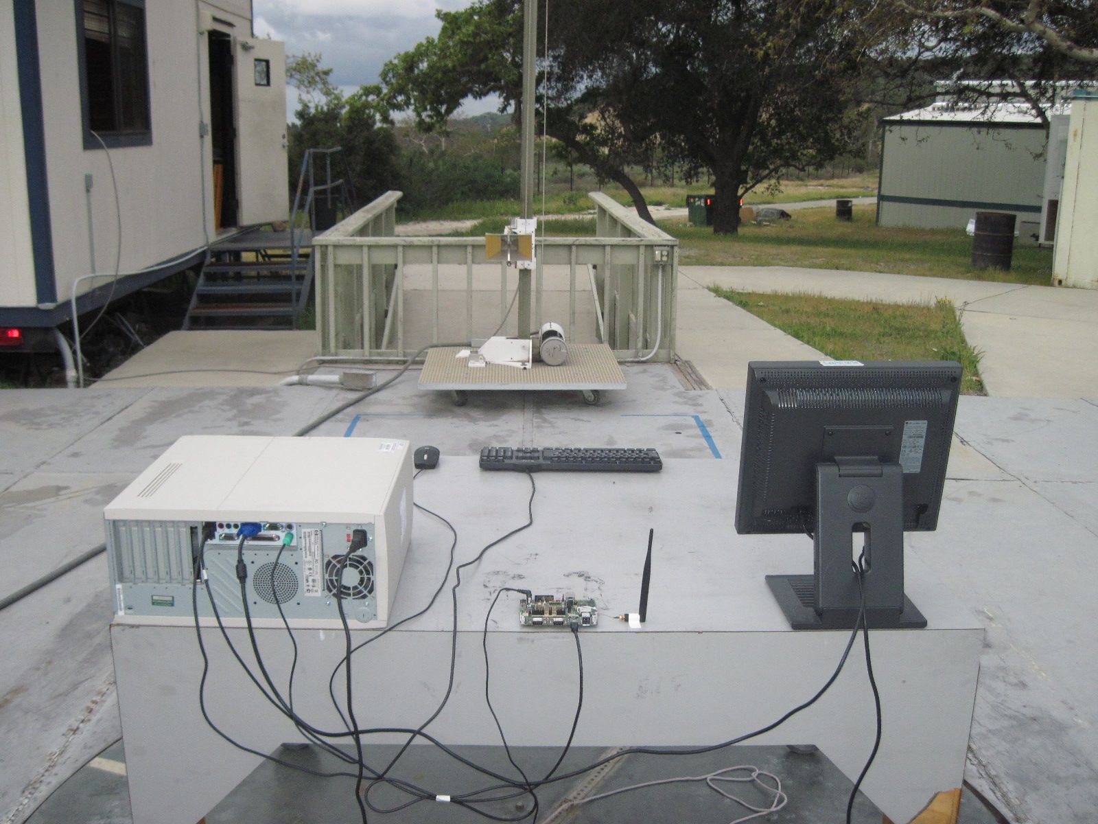
Document Text
Text extracted from the exhibit documents filed with the FCC. Open a document above to read the original.
Users Manual
Part Number 900-579 Revision A January 2011 PremierWave TM EN User Guide PremierWave EN User Guide 2 Copyright & Trademark © 2011 Lantronix. All rights reserved. No part of the contents of this book may be transmitted or reproduced in any form or by any means without the written permission of Lantronix. Printed in the United States of America. Ethernet is a trademark of XEROX Corporation. Windows is a trademark of Microsoft Corporation. Linux is a registered trademark of Linus Torvalds. Contacts Lantronix Corporate Headquarters 167 Technology Drive Irvine, CA 92618, USA Phone: 949-453-3990 Fax: 949-450-7249 Technical Support Online: www.lantronix.com/support Sales Offices For a current list of our domestic and international sales offices, go to the Lantronix web site at www.lantronix.com/about/contact. Disclaimer & Revisions The information in this guide may change without notice. The manufacturer assumes no responsibility for any errors that may appear in this guide. Revision History Date Rev. Comments January 2011 A Initial Document. PremierWave EN User Guide 3 Table of Contents Copyright & Trademark ___________________________________________________ 2 Contacts ______________________________________________________________ 2 Disclaimer & Revisions ___________________________________________________ 2 Revision History ________________________________________________________ 2 Table of Contents _______________________________________________________ 3 List of Figures __________________________________________________________ 6 List of Tables ___________________________________________________________ 6 1: Using This Guide 9 Purpose and Audience ___________________________________________________ 9 Summary of Chapters ____________________________________________________ 9 Additional Documentation ________________________________________________ 11 2: Introduction 12 Key Features __________________________________________________________ 12 Applications ___________________________________________________________ 12 Protocol Support _______________________________________________________ 13 Troubleshooting Capabilities ______________________________________________ 13 Configuration Methods __________________________________________________ 13 Addresses and Port Numbers _____________________________________________ 14 Hardware Address __________________________________________________ 14 IP Address ________________________________________________________ 14 Port Numbers ______________________________________________________ 14 Product Information Label ________________________________________________ 15 3: Using DeviceInstaller 16 Accessing PremierWave EN using DeviceInstaller ____________________________ 16 Device Details Summary _________________________________________________ 17 4: Network Settings 19 Network Interface Settings _______________________________________________ 19 Network Link Settings ___________________________________________________ 21 WLAN Settings ________________________________________________________ 22 WLAN Link Information Commands _____________________________________ 22 WLAN Profiles _________________________________________________________ 24 WLAN Profile Management Commands _________________________________ 24 WLAN Profile Basic Settings __________________________________________ 25 WLAN Profile Advanced Settings _______________________________________ 25 WLAN Profile Security Settings ________________________________________ 26 PremierWave EN User Guide 4 WLAN Profile WEP Settings ___________________________________________ 27 WLAN Profile WPA and WPA2/IEEE802.11i Settings _______________________ 28 5: Line and Tunnel Settings 31 RS232/RS485 ______________________________________________________ 31 USB-CDC-ACM ____________________________________________________ 31 Line Settings __________________________________________________________ 32 Tunnel Settings ________________________________________________________ 33 Accept Mode _______________________________________________________ 33 Connect Mode _____________________________________________________ 35 Packing Mode ______________________________________________________ 36 6: Configurable Pin Manager 37 CPM: Configurable Pins _________________________________________________ 37 CPM: Groups ______________________________________________________ 39 7: Services Settings 40 DNS Configuration _____________________________________________________ 40 Syslog Configuration ____________________________________________________ 40 8: Security Settings 41 SSL Settings __________________________________________________________ 41 Certificate Upload Settings ____________________________________________ 41 Authority Certificate Settings __________________________________________ 42 Certificate and Key Generation ________________________________________ 42 9: Maintenance and Diagnostics Settings 44 File System Configuration ________________________________________________ 44 File Display Commands ______________________________________________ 44 File Modification Commands __________________________________________ 44 File Transfer Commands _____________________________________________ 45 Query Port ____________________________________________________________ 45 Diagnostics ___________________________________________________________ 46 IP Sockets_________________________________________________________ 46 Ping ______________________________________________________________ 46 Trace route ________________________________________________________ 46 DNS Lookup _______________________________________________________ 47 Memory ___________________________________________________________ 47 Processes _________________________________________________________ 47 System Configuration ___________________________________________________ 48 PremierWave EN User Guide 5 10: Advanced Settings 49 Command Line Interface Settings _______________…
Text truncated - open the document above for the full version.
External Photos
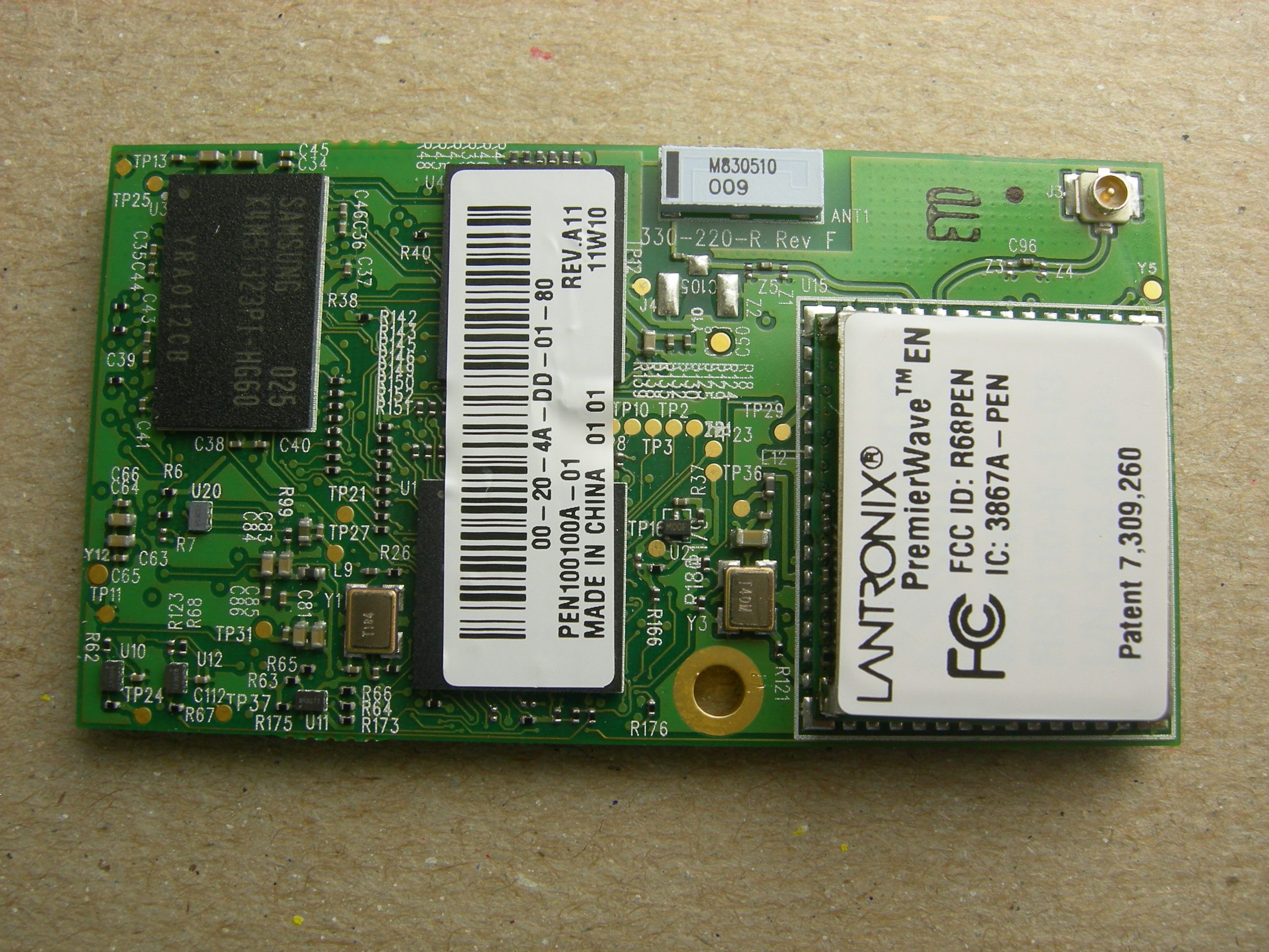
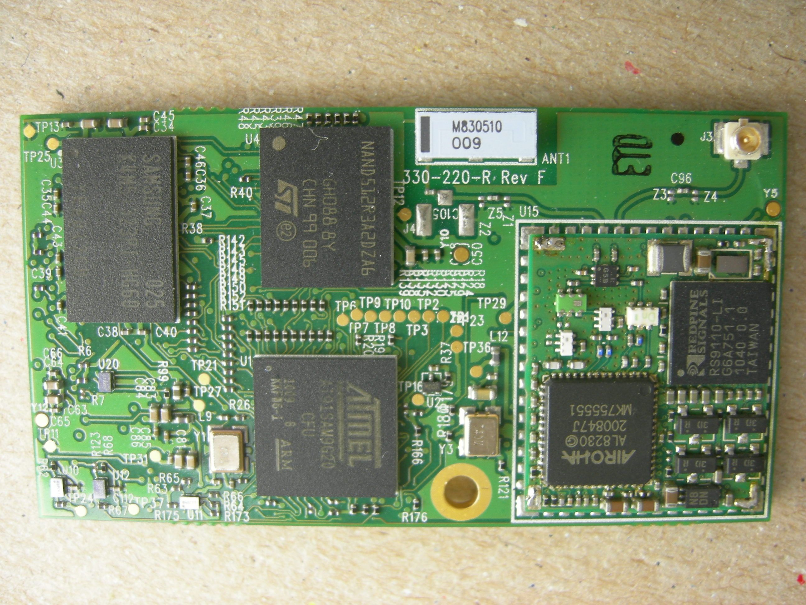
PremierWave EN Internal photo ANT 2 Top Internal Antenna Y3 X ’ tal 40MHz ANT 1 U1 ANT 2 Top ANT 1 Top External Antenna Y3 X ’ tal 40MHz U1 PremierWave EN Internal photo Bottom PremierWave EN Internal photo
ID Label/Location Info
LANTRONIX Description: LABEL SPEC, PREMIERWAVE AGENCY, ROHS Page: 1 of 2 Document Number: 461-131 Revision: C Revision History Rev. Description Date A Original issue 06/23/10 B Add TM (trademark) to PremierWave. 11/22/10 C Was “Patent. 7,309,260 B2”, change to “Patent. 7, 309,260” 01/25/11 0.74” +/- 0.01 0 .6 2 ” +/ - 0.01 2 R 0.031” +/-0.01 4 6 7 8 9 3 5 Patent. 7,309,260 PremierWave TM EN FCC ID: R68PEN IC: 3867A - PEN R XXXXXXXXXX XXXXXXXXXX Example Pat ent. 7,309,260 PremierWave TM EN FCC I D: R68PEN IC: 3867A - PEN LANTRONIX Description: LABEL SPEC, PREMIERWAVE AGENCY, ROHS Page: 2 of 2 Document Number: 461-131 Revision: C Notes: 1 Blank Label material is 460-552-R. Use ap propriate ink resin for printed image to last the l ifetime of product. Company Logo. “Lantronix” Graphic. Place & size a pproximately as shown. Product Logo. Human Readable Text: Font Style = Ar ial or equivalent. Bold Font. Font Size = 7 pt (a pproximately 0.07” character height). Content is “ PremierWave TM EN “. Place approximately as shown. FCC Logo. “FCC” Graphic. Place & size approximate ly as shown. Minimum 3mm height. FCC & CANADA RADIO ID. Human Readable Text: Font Style = Arial or equivalent. Font Size = 7 pt (ap proximately 0.07” character height). Place as show n. Content must read literally without quotes “FCC ID: R68PEN” “IC: 3867A-PEN” Currently not printed, but space reserved for JAPAN TELECOMMUNICATION Mark. S ize and place approximately as shown. Diameter sha ll be 3 mm minimum. Currently not printed, but space reserved for JAPAN RADIO EQUIPMENT Mark. Size and place approximatel y as shown. Currently not printed, but space reserved for JAPAN CERTIFICATION NUMBER: Human Readable Text. Text Format and size same as 5. Place as shown. Content must read literally without quotes “XXXXXXXXXX ” “XXXXXXXXXX ” Patent Number. Human Readable Text: Text Format a nd size same as 5. Place as shown. Content must re ad literally without quotes “Patent. 7,309,260” 10 All homogeneous materials used in the const ruction of this component/assembly shall comply wit h the current EU Directive 2002/95/EC, Restriction of Hazardous Substances (RoHS), and Article 7 and 57 of Regulation (EC) No 1907/200 6 (REACH Regulation). 2 3 4 9 5 6 7 8
Operational Description
PremierWave EN Data Sheet 940-001A January 2011 Copyright© 2011, Lantronix. All rights reserved. Key Features • The only complete, dual band radio, integrated solution in a compact form factor • Up to 921 Kbps Serial Interface • USB 2.0 Full Speed(host and device), High Speed SPI (Master/Slave) • 9 Configurable Pins • 10/100 Base T Ethernet MAC and PHY • 802.11 a/b/g/n Dual band Radio • Antenna Diversity • Vareity of management and configuration options, including web interface • Supports most industry standard Network Protocols • IEEE 802.11i-compliant radio with AES-CCMP and TKIP encryption • Complete suite of 802.1x Enterprise Authentication Protocols (EAP) including EAP-TLS, EAP-TTLS, PEAP, EAP-Fast and LEAP • End-to-end SSL TLS and SSH tunneling • SSL Client & Server, Selectable 128/256/512/768/1024/2048 Bit Certificates • SSH Client, 8 Server Selectable 128/256/512/768/1024 Bit Public/Private Key support • TLS • ENCRYPTION: AES, 3DES and RC4 Encryption for SSH & SSL • AUTHENTICATION: SHA-1, MD5, Base-64 • RoHS and REACH compliant • Industrial temperature: -40 to +85 ̊ C • High-performance processor (440 MIPS at 400 MHz) • 3.3V power PremierWave™ EN Data Sheet General Description PremierWave™ EN delivers a new dimension of Wi-Fi networking with the highest levels of security to virtually any electronic product. It provides affordable connectivity in a compact form factor, enabling OEMs to add Wi-Fi or wired Ethernet networking to their products on a single PCB design. With a choice of flexible, media-independent modules ranging from Ethernet, Wi-Fi and ultra- secure Wi-Fi, the PremierWave EN takes the complexity out of RF design and networking. OEMs can focus on their core competencies while minimizing engineering risk, shortening development time and reducing development cost. PremierWave EN has a dedicated 32-bit processor module running at 400 MHz and features 32 Kbyte Data Cache, 32 Kbyte Instruction Cache, embedded 64 Kbyte ROM, 16 Kbyte SRAM and a Memory Management Unit. With options for up to 64Mbyte of SDRAM and up to 256Mbyte of NAND Flash, PremierWave EN can easily manage wireless connectivity and web services. With its combination of high performance CPU, ample memory, variety of serial interface options (Serial, I2C, High Speed SPI, USB 2.0) and Linux OS, PremierWave EN can be designed as the primary host processor, for most demanding embedded applications. PremierWave EN offers an unmatched portfolio of security technologies. PremierWave EN goes far beyond compliance with the popular 802.11i, WPA and WPA2 wireless security specifications. It ensures data integrity and privacy for highly sensitive requirements, such as medical or financial applications. PremierWave Antenna SKU Options PremierWave SKU options Antenna Port 1 Connection Antenna Port 2 Connection SKU 1 with chip antenna Internal chip antenna U.FL for external antenna SKU 2 without chip antenna U.FL for external antenna U.FL for external antenna SKU 3 without wireless LAN None None PremierWave EN Data Sheet 940-001a January 2011 Page 2 of 6 PremierWave EN Block Diagram Additional Documentation For supporting product documentation, or the most current version of this document, please visit the Lantronix Web site at www.lantronix.com/support/documentation. Document Description PremierWave EN Integration Guide Information about the PremierWave EN hardware, testing the PremierWave EN using the demonstration board, and integrating the PremierWave EN into your product. PremierWave EN User Guide Provides information needed to configure, use, and update the PremierWave EN firmware. PremierWave EN Command Reference Lists and explains PremierWave EN command line and XML commands. PremierWave Evaluation Board Quick Start Guide Briefly explains how to connect the PremierWave and assign an IP address. PremierWave Evaluation Board User Guide Provides information needed to use the PremierWave EN on the evaluation board. Management and Configuration The PremierWave EN offers the following: • Serial & Telnet Login • Internal WebManager (SSL Option for secure login) • Enterprise CLI (over Serial Ports, Telnet or SSH) • XML Configuration Records via CLI or FTP • Windows-based DeviceInstaller software • Firmware: Upgradeable via FTP, HTTP, Serial Port Mechanical, Thermal and Enviromental Specifications Weight 8.5 grams Temperature Operating range: -40°C to +85°C (-40°F to 185°F) Storage range: -40°C to +85°C (- 40°F to 185°F) Relative Humidity Operating: 5% to 95% non- condensing Shock/Vibration Non-operational shock: 50 g's, Non-operational vibration: 5 g's Top View PremierWave EN Data Sheet 940-001a January 2011 Page 3 of 6 PCB Interface PremierWave EN comes with an industry standard 80-pin connector (Hirose DF40C-80DP-0.4V(51)). A host board can connect to PremierWave EN by deploying a Hirose DF40C(2.0)-80DS-0.4V(51) mating connector. PremierWave Connector Pins and Descriptions Pin# Pin Name Dir Function Name 1 GND Ground. Connect to unit signal ground. 2 NRESETIN I Reset (Active Low) 3 HDPB I/O USB Host Port B + 4 NRSTTODFLT I Reset Configuration to Defaults (Active Low) 5 HDMB I/O USB Host Port B - 6 TX1 O UART 1 Transmit 7 GND 8 RTS1 O UART 1 Request To Send 9 S3V3 3.3V Power Input 10 RX1 I UART 1 Receive 11 S3V3 3.3V Power Input 12 CTS1 I UART1 Clear To Send 13 GND 14 CP1 I/O I/O Configurable Pin 1 15 S3V3 3.3V Power Input 16 CP2 I/O I/O Configurable Pin 2 17 S3V3 3.3V Power Input 18 CP3 I/O I/O Configurable Pin 3 19 GND 20 CP4 I/O I/O Configurable Pin 4 21 E_SPEED O Ethernet Link LED 22 GND 23 E_LNKACT O Ethernet Activity LED 24 TX2 O UART 2 Transmit 25 W_LINKLED O Wireless LAN Status LED 26 RTS2 O UART 2 Request To Send 27 CP6 I/O I/O Configurable Pin 6 28 RX2 I UART 2 Receive 29 RSVD I Reserved (DO NOT CONNECT) 30 CTS2 I UART 2 Clear To Send 31 I2CSCL I/O I2C Clock 32 CP5 I/O I/O Configurable Pin 5 33 I2SDA I/O I2C Data 34 DBTXD O Debug UART Tx 35 GND 36 DBRXD I Debug UART Rx 37 NSPI1_IRQ I/O SPI IRQ 38 CP8 I/O I/O Con…
Text truncated - open the document above for the full version.
Operational Description
+ 802.11 abgn solution with Dual Band Radio (2.4GHZ and 5GHz) + Linux Operating System with IPV6 + Adds WiFi to devices with the highest enterprise-grade security and authentication protocols + Lantronix SmartRoam ™ technology provides seamless mobile connectivity and improved reliability + Includes full TCP/IP stack, web server + Robust set of interfaces which include Ethernet, Serial, USB, I2C, and SPI + Low power consumption modes + Powerful applications customization platform with 32 Bit ARM9 Processor + Virtual IP (VIP) Access ™ for gaining remote connectivity even behind firewalls PremierWave ™ EN delivers a new dimension of WiFi networking with the highest levels of security to virtually any device or electronic product. It provides affordable connectivity in a compact form factor, enabling OEMs to add WiFi or wired Ethernet networking to their products on a single PCB design. With a choice of flexible, media-independent modules ranging from Ethernet, WiFi and ultra-secure WiFi, the PremierWave EN takes the complexity out of RF design and networking. OEMs can focus on their core competencies while minimizing engineering risk, shortening development time and reducing development cost. WiFi Network Processor Module PremierWave EN has a dedicated 32-bit processor module that manages wireless connectivity and web services. With its high performance, ample memory and Linux OS, PremierWave EN can be designed as the primary host processor, for demanding applications. Bulletproof Security With an unmatched portfolio of security technologies, PremierWave EN goes far beyond compliance with the popular 802.11i, WPA and WPA2 wireless security specifications. It ensures data integrity and privacy for highly sensitive requirements, such as medical or financial applications. DeviceLinx ® THE MOST FEATURE RICH, DEPLOyMEnT-READy WIFI nETWORkInG AnD WEB SERVER MODULE PremierWave ™ EN Wireless Device Server + IEEE 802.11i-compliant radio with AES-CCMP and TKIP encryption + PSK and complete suiteof 802.1x Extensible Authentication Protocols (EAP) including EAP-TLS, EAP-TTLS, PEAP, EAP-Fast and EAP-PEAP + End-to-end SSL TLS and SSH tunneling High Reliability WiFi for Better Mobility With exclusive SmartRoam technology, PremierWave EN continuously tracks the signal strength of access points (AP) within range. If necessary, pre-authentication and caching enables smooth and automatic transition to an access point with a stronger signal. This enhances mobility within a building, warehouse or across a campus network with less time spent re-authenticating due to a lost connection or re-associating to a stronger signal. Scan, Gather and Report Radio Parameters With an unmatched portfolio of security technologies, PremierWave EN scans current AP and Received Signal Strength radio parameters, as well as authentication and negotiated encryption types for the current association, and displays them on a web page. This enables remote technicians to diagnose problems as they occur and troubleshoot over any IP network without a service call, reducing support costs and unnecessary visits. Linux and Web Server Technologies Featuring Linux, PremierWave’s integrated CGI-capable web server transforms a standalone device into a networked product that can be managed remotely via a standard web browser. CGI capability enables users to remotely monitor and collect information from the device in real-time and send the information to dynamic web pages. Flexible & Intelligent Design Designed with an on-board antenna and option for external antennas and diversity, it provides the flexibility to locate the antenna and connector based on design requirements. It also includes a user- controlled, intelligent power management option to shut down the radio during periods of inactivity, minimizing current consumption. FCC Certified for Immediate Deployment PremierWave EN will be module-certified by the U.S. Federal Communications Commission (FCC) enabling OEMs to leverage the Lantronix FCC license grant and bypass 802.11 regulatory testing. PremierWave EN will also be pre-tested for European telecommunications regulations. PremierWave EN Key Features + network Interface: Wireless 802.11a, 802.11b, 802.11g, and 802.11n, Ethernet + Dual Radio Frequency 2.4GHz and 5 GHz + Management, Configuration and Encryption suite + Serial Interface: Serial (UART, RS232, RS485), USB, SPI, I2C + Architecture: Lantronix 32-bit processor (ARM Core) with Linux + Virtual IP Access Ordering Information Please contact your Lantronix Representative for more details. + To speak with a Lantronix sales representative in North America, call +1 (800) 422-7055. + For a full listing of Lantronix worldwide offices or to locate a partner, please visit www.Lantronix.com/about/contact.html + Part number + Description PEn100100A-01 PremierWave EN 802.11 abgn Device Server with internal Antenna, BULK - Minimum order quantity 10 units - Available April 2011 PEn10010SA-01 PremierWave EN 802.11 abgn Device Server with internal Antenna, SAMPLE - Order quantities of up to 10 - Available Now PEn10010nA-01 PremierWave EN 802.11 abgn Device Server without internal antenna, BULK - Minimum order quantity 10 units - Available April 2011 PEn10010nASA-01 PremierWave EN 802.11 abgn Device Server without internal antenna, SAMPLE - Order quantities of up to 10 - Available Now PWDk1000-01 PremierWave no module Development Kit, sample must be purchased - Evaluation Board, Power Supply, RS-232 Cable, Cat 5e Cable, USB Cable (A-B) - Available Now PWEV1000-01 PremierWave no module Evaluation Board, sample must be purchased. Includes power supply module. - Available Now CORPORATE HEADQUARTERS 167 Technology Drive | Irvine | CA 92618 | USA | t: 800.422.7055 | f: 949.450.7232 | [email protected] | www.lantronix.com © 2011, Lantronix, Inc. Lantronix, DeviceLinx and ManageLinx are registered trademarks, and PremierWave, VIP Access and SmartRoam are trademarks of Lantronix, Inc. All other tradema…
Text truncated - open the document above for the full version.
RF Exposure Info
MPE Calculations Systems operating under the provision of 47 CFR 1.1307(b)(1) shall be operated in a manor that ensures that the public is not exposed to radio frequency energy levels in excess of the FCC guidelines. The EUT will only be used with a separation of 20 centimeters or greater between the antenna and the body of the user or nearby persons and can therefore be considered a mobile transmitter per 47 CFR 2.1091(b). The MPE calculation for this exposure is shown below. Using the Antennas with highest output power: Taoglas Dipole Antenna The peak radiated output power (EIRP) is calculated as follows: Antenna Frequency (GHz) Power input to the antenna (P) (dBm) Power gain of the antenna (G) (dBi) EIRP (P+G) (dBm) EIRP Log -1(dBm/10) (mW) Taoglas 2.412-2.462 20.305.0025.30 338.84 Taoglas 5.18-5.24 13.805.0018.80 75.86 Taoglas 5.26-5.32 15.405.0020.40 109.65 Taoglas 5.5-5.7 15.305.0020.30 107.15 Taoglas 5.745-5.825 15.105.0020.10 102.33 EIRP = P + G Where P = Power input to the antenna (mW). G = Power gain of the antenna (dBi) The numeric gain (G) of the antenna with a gain specified in dB is determined by: Antenna Frequency (GHz) Antenna Gain (G) (dBi) Numeric Antenna Gain Log -1(dBm/10) (dB) Taoglas 2.412-2.4625.003.16 Taoglas 5.18-5.245.003.16 Taoglas 5.26-5.325.003.16 Taoglas 5.5-5.75.003.16 Taoglas 5.745-5.8255.003.16 G = Log -1 (dB antenna gain/10) Power density at the specific separation: Antenna Frequency (GHz) Power input to the antenna (P) (mW) Numeric Power Gain of the Antenna (G) (dB) Maximum Power Spectral Density S=PG/(4R 2 π) (mW/cm 2 ) Maximum Power Spectral Density Limit (mW/cm 2 ) Taoglas 2.412-2.462 107.153.160.067 1.00 Taoglas 5.18-5.24 23.993.160.015 1.00 Taoglas 5.26-5.32 34.673.160.022 1.00 Taoglas 5.5-5.7 33.883.160.021 1.00 Taoglas 5.745-5.825 32.363.160.020 1.00 S = PG/(4R 2 π) Where S = Maximum power density (mW/cm 2 ) P = Power input to the antenna (mW). G = Numeric power gain of the antenna R = Distance to the center of the radiation of the antenna (20cm = limit for MPE) The maximum permissible exposure (MPE) for the general population is 1mW/cm 2 . The power density at 20cm does not exceed the 1mW/cm 2 limit. Therefore, the exposure condition is compliant with FCC rules.
Test Report
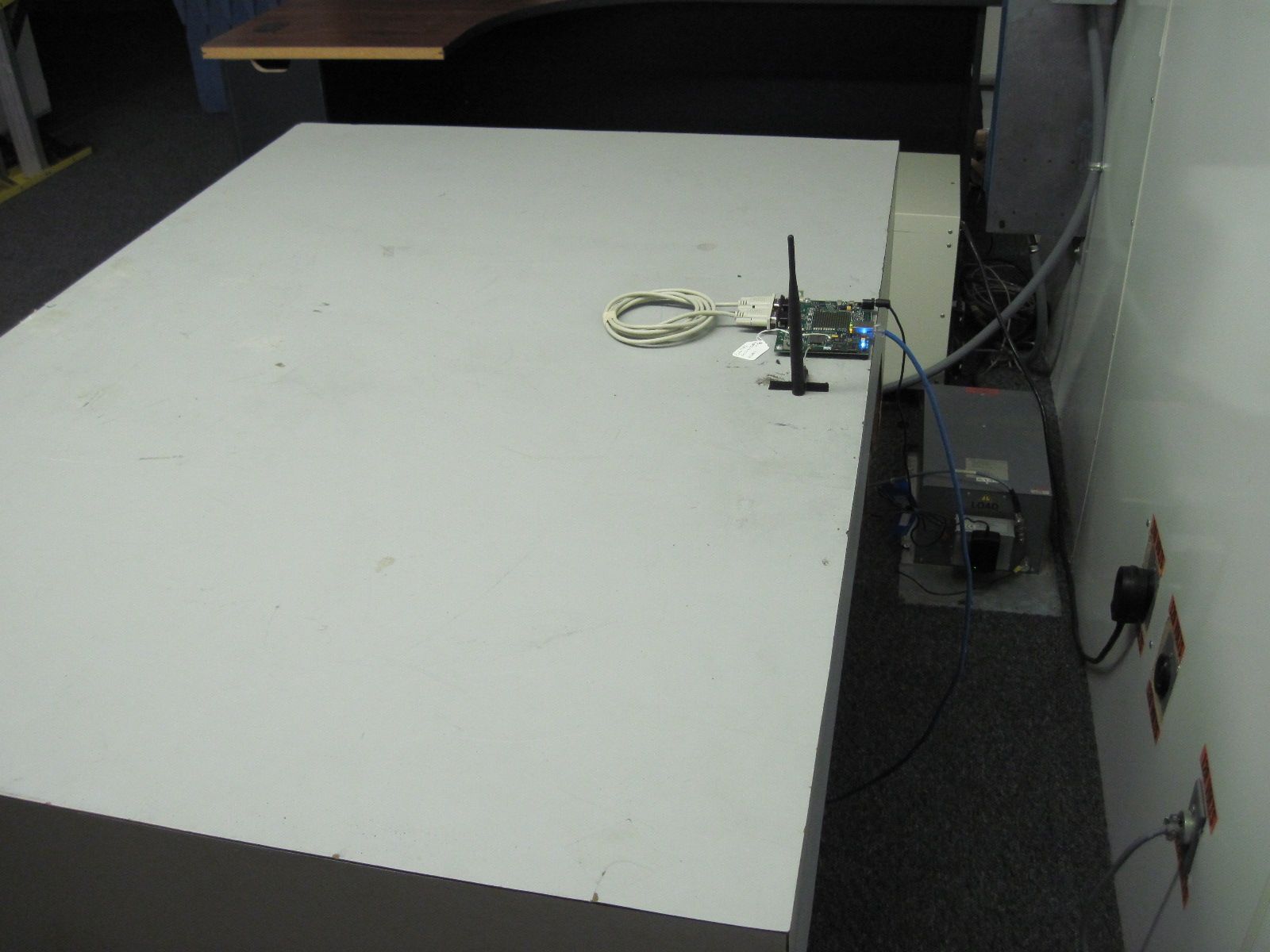
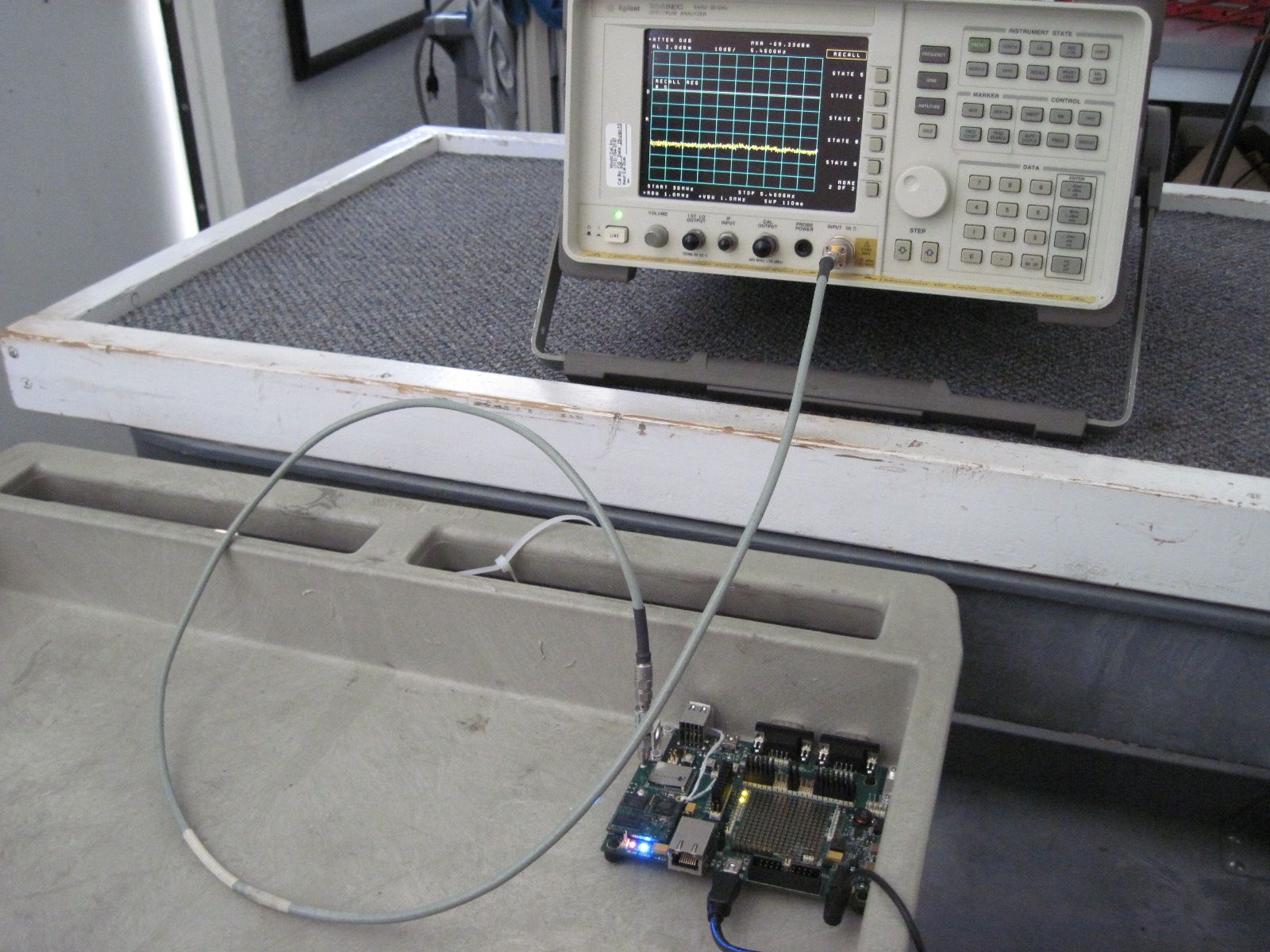
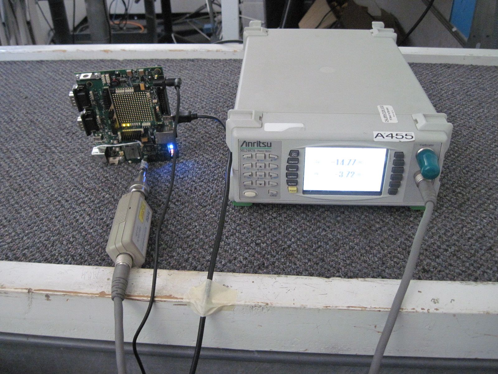
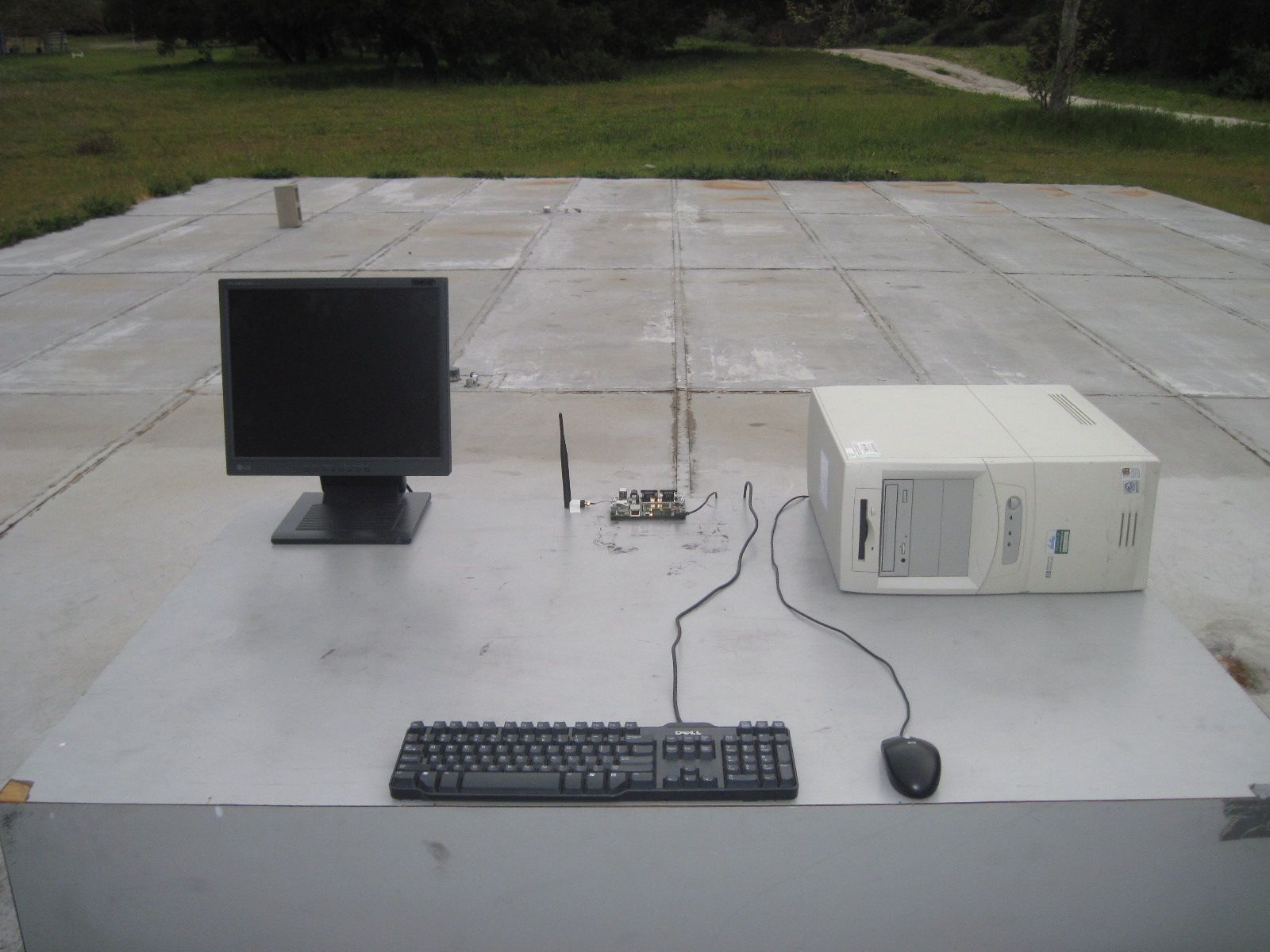
Page 1 of 18 Report Number: LANTR-101029F Revision Number: A1 Modular Approval Test Report And Application for Grant of Equipment Authorization TEST REPORT PERTAINING TO: Equipment Under Test Model Number(s) Wireless Device Server PremierWave EN CONFIGURATION IEEE 802.11a / 802.11b / 802.11g / 802.11n with a Taoglas 5dBi; RP-SMA(M) Hinged 90° Antenna MEASUREMENTS PERFORMED IN ACCORDANCE WITH THE FOLLOWING STANDARD (S) Regulatory Standard(s) 47 CFR Part 15, Subpart E Section 15.407 (UNII Devices) Test Method: ANSI C63.4: 2003 American National Standard for Methods of Measurement of Radio-Noise Emissions from Low- Voltage Electrical and Electronic Equipment in the Range of 9 kHz to 40 GHz PREPARED FOR: PREPARED BY: Lantronix Aegis Labs, Inc. 167 Technology Drive 8 Rancho Circle Irvine, California 92618 Lake Forest, CA 92630 Contact(s): Mr. Daryl Miller Agent(s): Mr. Steve Kuiper Mr. Johnny Candelas Test Report #: LANTR-101029F Test Report Revision: A1 REPORT BODY APPENDICES TOTAL PAGES A B PAGES 18 179 1 198 The contents of this report shall not be reproduced except in full, without the written approval of Aegis Labs, Inc. The Lantronix logo is used for identification purposes only and is a registered trademark of Lantronix Certificate Number: 1111.01 Page 2 of 18 Report Number: LANTR-101029F Revision Number: A1 TABLE OF CONTENTS SECTION TITLEPAGE COVER SHEET......................................................................................................... 01 TABLE OF CONTENTS.................................................................................................................... 02 1.0 REGULATORY COMPLIANCE GUIDELINES................................................................ 03 1.1 Guidelines For Testing To Emissions Standards..................................................................... 03 2.0 SUMMARY OF REGULATORY LIMITS.................................................................................. 04 3.0 ADMINISTRATIVE DATA AND TEST DESCRIPTION..................................................... 12 4.0 DESCRIPTION OF EUT CONFIGURATION....................................................................... 13 4.1 EUT Description ......................................................................................................... 13 4.2 EUT Configuration......................................................................................................................... 14 4.3 List of EUT Sub-Assemblies and Host Equipment........................................................................... 14 4.4 I/O Cabling Diagram and Description ................................................................................. 15 4.5 EMC Test Hardware and Software Measurement Equipment.............................................................. 16 5.0 CONDITIONS DURING EMISSIONS MEASUREMENTS................................................... 17 5.1 General..................................................................................................................... 17 5.2 Conducted Emissions Test Setup.......................................................................................................... 17 5.3 Radiated Emissions Test Setup......................................................................................... 18 APPENDICES A Test Data B Modifications And Recommendations Page 3 of 18 Report Number: LANTR-101029F Revision Number: A1 1.0 REGULATORY COMPLIANCE GUIDELINES Aegis Labs, Inc. operates as both a Nevada and California Corporation with no organizational or financial relationship with any company, institution, or private individual. Testing and engineering functions provided by Aegis Labs were furnished by RF technicians and engineers with accredited qualifications and training credentials to carry out their duties. The object of this report was to publish verifiable test results of an EUT subjected to the tests outlined in the standard listed on the cover page of this report. 1.1 Guidelines For Testing To Emissions Standards This standard for EMC emission requirements apply to electrical equipment for Information Technology Equipment (ITE). Compliance to these standards and in combination with the other standards listed in this test report can be used to demonstrate presumption of compliance with the protection requirements of the appropriate agency standard. The purpose of this standard is to specify minimum requirements for emissions regarding electromagnetic compatibility (EMC) and protect the radio frequency spectrum 9 kHz. – 400 GHz. from unwanted interference generated from electrical/digital systems that intentionally or unintentionally generated RF energy. The emissions standards, normative documents and/or publications were used to conduct all tests performed on the equipment herein referred to as “Equipment Under Test”. Page 4 of 18 Report Number: LANTR-101029F Revision Number: A1 2.0 SUMMARY OF TEST RESULTS 802.11a Mode (5150-5350 MHz) Antenna 1 EMISSIONS STANDARD FCC Part 15 Section Description Results Comments Operation in the 5.15-5.25 GHz Band 15.407(d) Any UNII device shall use a transmitting antenna that is an integral part of the device. PASSED The antenna will be integral when installed in a notebook computer 15.407(e) UNII devices will be restricted to indoor operations. PASSED Refer to “User’s Manual” Exhibit 15.407(a)(1) 26dB emissions bandwidth in MHz. N/A Refer to Plots Section 15.407(a)(1) Peak transmit power shall not exceed the lesser of 50mW or 4dBm+10logB (where B = 26dB emissions bandwidth). PASSED Refer to Output power Section 15.407(a)(1) The peak power spectral density shall not exceed 4dBm in any 1MHz band. PASSED Refer to Plots Section 15.407(a)(1) Peak transmit power and the peak power spectral density shall be reduced by the amount in dB that the transmitting antenna exceeds 6dBi. N/A All antennas tested have less than 6dBi antenna gain (Please see the antenna data sheets) 15.407(b)(6) 1…
Text truncated - open the document above for the full version.
Test Report
COVER PAGE Test of PremierWave 802.11 Wireless Card To: FCC 47 CFR Part 15.407 Test Report Serial No.: AGSL01-U1 Rev A TITLE PAGE TEST REPORT FROM Test of PremierWave 802.11 Wireless Card To: FCC 47 CFR Part 15.407 & IC RSS-210 Test Report Serial No.: AGSL01-U1 Rev A This report supersedes None Applicant: Lantronix Inc 167 Technology Drive Irvine California 92618, USA Product F unction: 802.11 Wireless Device Server Client device without radar detection Copy No: pdf Issue Date: 18th April 2011 This Test Report is Issued Under the Authority of; MiCOM Labs, Inc. 440 Boulder Cour t, Suite 200 Pleasanton, CA 94566 USA Phone: +1 (925) 462-0304 Fax: +1 (925) 462-0306 www.micomlabs.com TESTING CERTIFICATE #2381.01 MiCOM Labs is an ISO 17025 Accredited Testing Laboratory This test report may be reproduced in full only. The document may only be updated by MiCOM Labs personnel. Any changes will be noted in the Document History section of the report. Title: PremierWave 802.11 Wireless Card To: Serial #: Issue Date: Page: FCC 47 CF R Part 15.407 AGSL01-U1 Rev A 18th April 2011 3 of 36 This test report may be reproduced in full only. The document may only be updated by MiCOM Labs personnel. Any changes will be noted in the Document History section of the report. MiCOM Labs, 440 Boulder Court, Suite …
Text truncated - open the document above for the full version.
Contact Information
Applicant
Eric Bass(VP of Engineering)
Technical Contact
Aegis LabsSteve Kuiper
[email protected]949 751 8089
32565 B Golden Lantern · Dana Point, California · United States
Test Firm
AEGIS Labs, Inc.Steve Kuiper
Technical Specifications
| # | Rule Parts | Frequency Range | Power Output |
|---|---|---|---|
| 3 | 15E | 5.50 GHz - 5.70 GHz | 34.00 mW |
Other Applications from Lantronix, Inc.
R68FOX5BT
Aug 27, 2026FOX5 Series
Equipment Class
DSS - Part 15 Spread Spectrum TransmitterR68XPICO600
Apr 08, 2026Wi-Fi & Bluetooth Module
Equipment Class
NII - Unlicensed National Information Infrastructure TXR68OQ8550
Mar 04, 2026Open-Q 8550CS SOM
Equipment Class
DTS - Digital Transmission SystemR68OQ2200S
Jul 17, 2024Wireless Module
Equipment Class
DTS - Digital Transmission System
R68E213W
Nov 21, 2022E210 Series
Equipment Class
DTS - Digital Transmission System