R68PWXCHSPAPremierWave XC HSPA+
Lantronix, Inc.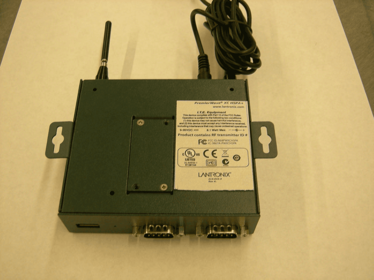
Click to zoom
Application Details
- Equipment Class
- PCB - PCS Licensed Transmitter
- Date of Grant
- Apr 30, 2013
- Application Purpose
- Original Equipment
- Date of Application
- Apr 30, 2013
- Equipment Note
- PremierWave XC HSPA+
- Frequency Range
- 1852.40000000 - 1907.60000000
- Company
- Lantronix, Inc.
- Country
- United States
Documents & Files
Document Text
Text extracted from the exhibit documents filed with the FCC. Open a document above to read the original.
Users Manual
Part Number 900-678-R Revision A May 2013 PremierWave XC HSPA+ User Guide PRELIMINARY DRAFT PRELIMINARY DRAFT PremierWave XC HSPA+ User Guide2 Copyright & Trademark © 2013 Lantronix, Inc. All rights reserved. No part of the contents of this book may be transmitted or reproduced in any form or by any means without the written permission of Lantronix. Lantronix® registered trademark of Lantronix, Inc. DeviceInstaller and PremierWave© are trademark of Lantronix, Inc. Windows® and Internet Explorer® are registered trademarks of Microsoft Corporation. Mozilla® and Firefox® are registered trademarks of the Mozilla Foundation. Chrome™ is a trademark of Google, Inc. Opera™ is a trademark of Opera Software ASA. Tera Terma is a registered trademark of Vector, Inc. All other trademarks and trade names are the property of their respective holders. Warranty For details on the Lantronix warranty policy, please go to our web site at www.lantronix.com/support/warranty . Contacts Lantronix Corporate Headquarters 167 Technology Drive Irvine, CA 92618, USA Toll Free:800-526-8766 Phone:949-453-3990 Fax:949-450-7249 Technical Support Online:www.lantronix.com/support Sales Offices For a current list of our domestic and international sales offices, go to the Lantronix web site at www.lantronix.com/about/contact . Disclaimer The information in this guide may change without notice. The manufacturer assumes no responsibility for any errors that may appear in this guide. Revision History DateRev.Comments May 2013AInitial document for firmware release 7.7.0.0R27. PRELIMINARY DRAFT PRELIMINARY DRAFT PremierWave XC HSPA+ User Guide3 Table of Contents List of Figures _____________________________________________________________ 9 List of Tables _____________________________________________________________ 10 1: Using This Guide 12 Purpose and Audience _____________________________________________________ 12 Summary of Chapters ______________________________________________________ 12 Additional Documentation ___________________________________________________ 13 2: Introduction 14 Key Features _____________________________________________________________ 14 Applications ______________________________________________________________ 14 Protocol Support _________________________________________________________ 14 Troubleshooting Capabilities _________________________________________________ 15 Configuration Methods _____________________________________________________ 15 Addresses and Port Numbers ________________________________________________ 16 Hardware Address _____________________________________________________ 16 IP Address ___________________________________________________________ 16 Port Numbers _________________________________________________________ 16 Product Information Label ___________________________________________________ 16 3: Installation of PremierWave XC HSPA+ 18 Package Contents _________________________________________________________ 18 User-Supplied Items _______________________________________________________ 18 Hardware Components ____________________________________________________ 18 Front/Top Panel _______________________________________________________ 18 Back Panel ___________________________________________________________ 23 Installing the PremierWave XC HSPA+ ________________________________________ 23 4: Using DeviceInstaller 25 Accessing PremierWave Using DeviceInstaller __________________________________ 25 Device Detail Summary _____________________________________________________ 25 5: Configuration Using Web Manager 27 Accessing Web Manager ___________________________________________________ 27 Device Status Page ____________________________________________________ 28 Web Manager Components _________________________________________________ 29 Navigating Web Manager ___________________________________________________ 30 PRELIMINARY DRAFT PRELIMINARY DRAFT PremierWave XC HSPA+ User Guide4 6: Network Settings 32 Network 1 (eth0) Interface Settings ____________________________________________ 32 To Configure Network Interface Settings ____________________________________ 33 To View Network Interface Status _________________________________________ 33 Network 1 (Link) Settings ___________________________________________________ 34 To Configure Network Link Settings ________________________________________ 34 Network 1 (Failover) _______________________________________________________ 35 To Configure Network 1 Failover Settings ___________________________________ 35 Network 2 (Cellular) Settings ________________________________________________ 35 To Configure Network 2 (Cellular Interface) Settings ___________________________ 36 Network 2 (Link) Settings ___________________________________________________ 36 To Configure Link Settings _______________________________________________ 37 Gateway ________________________________________________________________ 37 WAN ________________________________________________________________ 37 To Configure Gateway WAN Settings ______________________________________ 38 Port Forwarding _______________________________________________________ 38 To Configure Gateway Port Forwarding Settings ______________________________ 38 Static Routes _________________________________________________________ 39 To Configure Gateway Static Route Settings _________________________________ 39 DHCP Server _________________________________________________________ 40 To Configure Gateway DHCP Server Settings ________________________________ 40 7: Cellular 41 To Configure Cellular Settings ____________________________________________ 41 8: Action Settings 42 Alarms and Reports _______________________________________________________ 42 Actions _________________________________________________________________ 42 To Configure Action Settings _____________________________________________ 43 Digital Input ______________________________________________________________ 44 To C…
Text truncated - open the document above for the full version.
Cover Letter(s)
WTD 13.4.9 FCC Compliance Opinion LANT0018 Information about the Applicant Grantee (Company Name) Lantronix FCC Contact Person Daryl Miller Address 167 Technology City, State, Zip Irvine, CA 92618 Job Number LANT0018 Model PremierWave XC HSPA+ FCC ID R68PWXCHSPA Agent Thorsten Liebig and Jorg Rook for confidentiality request only Approval Type Original Equipment Class PCB – PCS Licensed Transmitter Rule Part 22H, 24E Overview The PremierWave XC HSPA+ incorporates an FCC approved radio module, FCC ID QIPPHS8-P inside the device. Reports for the original filing of this module are submitted in support of compliance of radio in this new device FCC ID: R68PWXCHSPA. Northwest EMC report submitted in support of continued compliance of output power and emissions. The PremierWave XC HSPA+ is an industrial‐grade 3G wireless solution offering Penta‐band HSPA+ performance, network redundancy, and enterprise‐level security for mission critical applications, time sensitive event tracking, and M2M connectivity. Confidentiality requested for allowed files. Request is properly addressed and referenced. Recommendation All items have been resolved and completed to my satisfaction; therefore I recommend this application for approval. Signature Dave Tolman, TCB Committee 4/30/2013
Cover Letter(s)
167 Technology Drive | Irvine | CA 92618 | USA | Tel: 949-453-3990 | Fax: 949-453-3995 | www.lantronix.com Cover Letter for Original Certification PremierWave XC HSPA+ FCC ID: R68PWXCHSPA FCC Part 15B FCC Part 22H FCC Part 24E The PremierWave XC HSPA+ is an industrial‐grade 3G wireless solution offering Penta‐band HSPA+ performance, network redundancy, and enterprise‐level security for mission critical applications, time sensitive event tracking, and M2M connectivity. PW‐XC HSPA+ Highlights: Penta‐band UMTS/HSPA+ Quad‐band GSM/GPRS/EDGE Ethernet‐to‐Cellular Routing Ethernet‐to‐Cellular Failover Serial‐to‐Cellular Tunneling Serial‐to‐Ethernet Tunneling SMS ‐ Shoulder Tap, Relay Control, SMS Tunneling, Event Notification Lantronix Device Server Application Suite 1 10/100 Ethernet Port 2 Serial Ports with data rates from 300 to 921600 baud 2 Digital Inputs,1 Relay Output 1 HS/FS USB 2.0 Port for connection to external storage device Industrial Grade Design The PremierWave XC HSPA+ incorporates an FCC approved module inside of the unit. The FCC ID for the internal module is FCC ID QIPPHS8‐P. The document submission for new FCC ID R68PWXCHSPA will include the test reports below from the original filing for FCC ID QIPPHS8‐P. The original test reports accurately represent the antenna port direct-connect test results when installed in FCC ID: R68PWXCHSPA. Part 22 test report.pdf, 7 Layers Report # MDE_CINTE_1108_FCCd Part 24 test report.pdf, 7 Layers Report # MDE_CINTE_1108_FCCe Module FCC ID: QIPPHS8‐P has been incorporated into new device FCC ID: R68PWXCHSPA per the design guides and specifications of the original module manufacturer.
External Photos
Cinterion Wireless Module PHS8-P PHS8-P Top side PHS8-P Bottom Side
ID Label/Location Info
UL 60950-1 FCC ID: R68PWXCHSPA IC: 3867A-PWXCHSPA LABEL,AGENCY,PWXN ART BY: DATE: REVISION: DATE: 100% TITLE: SCALE: METAL: MATERIAL: COLOR: ADHESION: 2 colors: Black, PMS Cool Gray 1 NEW PART NUMBER: 310-699-R OLD PART NUMBER: STATUS: LANTRONIX 167 TE IRVINE, CA 92618 (949) 453-3990 5 Mil Lexan N/A 3M# 467 unknown A. New Label 3/27/13 Ryan Bullock 3/27/13 COMMENTS: 1.70 B. Remove “Product containts RF Trans...” 4/29/13 PremierWave ® XC HSPA+ 310-699-R Rev B. 11 22 33 44 55 66 77 88 A A B B C C D D TITLE SIZE DWG NO REV SCALE SHEET OF DRAWNCHECKED QA MFG APPROVED 167 TechnologyIrvine, CA 92618(949) 453-3990 UNLESS OTHERWISE SPECIFIED DRILLED HOLE TOLERANCES .0135 TO .125 +.004 -.001 .126 TO .250 +.005 -.001 .251 TO .500 +.006 -.001 .501 TO .750 +.008 -.001 MACH. FINISH 63 OR BETTER REMOVE ALL BURRS & BREAK SHARP EDGES R.010 MAX.DO NOT SCALE DRAWING TOL .XX .XXX MATERIAL FINISH THIRD ANGLE PROJECTION THIS DOCUMENT CONTAINS INFORMATION PROPRIETARY TO LANTRONIX. ANY REPRODUCTION OF THIS DOCUMENT IS EXPRESSLY PROHIBITED EXCEPT AS LANTRONIX MAY OTHERWISE AGREE IN WRITING. 1 2 DIMENSIONS ARE IN INCHES FRACT. 1/64 ANG. 0 30' R PWCX3G Top Level Assy 1 1 D ryanb 4/3/2013 .01 .005 REVISION HISTORY REV DESCRIPTION DATE APPROVED Value 9/9/2003 -
Internal Photos
Cinterion Wireless Module PHS8-P PHS8-P Top side PHS8-P Bottom Side
Operational Description
SPE-11-8-032/E 05-August-2011 Page 1 of 16 SPECIFICATION Part No. : TG.09.0113 Product Name : Penta-band Cellular Hinged SMA Male Monopole Feature : Rotatable hinge design for optimal reception Top quality housing with brass hinge and connector Extended operation temperature range RoHS Compliant SPE-11-8-032/E 05-August-2011 Page 2 of 16 I. Introduction The TG.09 Penta-band Cellular Hinged Rotatable SMA antenna is a high efficiency monopole antenna. Compared to other much larger antennas on the market, it has superior wide-band high efficiency characteristics. This antenna is used by many of the leading wireless device providers in the world marketplace. The unique rotatable hinge design enables the user to rotate the antenna to the best angle for an optimal cellular signal reception. As the upper antenna element can move in any direction, it also reduces damage from impact force from any angle to the antenna, compared to traditional hinged right angle or fixed fight angle designs or straight antennas. The tiny dimensions of this antenna coupled with excellent RF performance and an aesthetic high end design feel make it the ideal cellular antenna for routers, vehicle tracking devices, telematics devices, remote monitoring systems, POS devices. The TG.09 as all monopole antennas works best connected directly to the ground-plane of the device main-board. Taoglas offers support services to characterize antenna efficiency on your individual device ground-plane. Please contact Taoglas regional support centre first if you wish to do PTCRB or network approvals with this antenna attached to your device, so we can check RF integration is correct and do a pre-test first to ensure optimized passive and active performance and a smooth and quick certification approval process. This antenna also comes in a white version. TG.09.0113W SPE-11-8-032/E 05-August-2011 Page 3 of 16 II. Specification ELECTRICAL Communication System Penta-band Cellular AMPS GSM DCS PCS UMTS Frequency 824 ~ 896 880~960 1710~1880 1850~1990 1710~2170 Efficiency (free space)* 21% 24% 23% 32% 31% Gain (dBi, free space)* 2.0 2.0 -1.0 -0.4 -0.1 Efficiency (mounted on PCB)* 39% 31% 78% 75% 75% Gain (dBi, mounted on PCB)* 1.0 -1.0 2.8 2.8 2.0 Impedance 50Ω Polarization Linear Radiation Pattern Omni-directional Input Power 10 W MECHANICAL Antenna Length 72 ± 1.5 mm Antenna Diameter 10 ± 0.3 mm Casing POM Connector SMA Male (Brass) ENVIRONMENTAL Temperature Range -40°C to 85°C Storage Temperature -40°C ~ +105°C Humidity Non-condensing 65°C 95% RH * Average efficiency and peak gain of antenna sitting 180 o in free space and mounted at the side of the PCB. Please refer to section IV for testing detail. SPE-11-8-032/E 05-August-2011 Page 4 of 16 III. Electrical Property – Return Loss Return Loss measure the amount of signal energy that is reflected back to the system (the network analyzer) due to impedance mismatch between the 50ohm network analyzer and the antenna. -3dBi means half of the energy is reflected back and -10dBi means 10% of energy is reflected back to the system. TG.09 Return Loss -25 -20 -15 -10 -5 0 60080010001200140016001800200022002400 (MHz) straight bend TG.09 tested with Agilent 8753ES IV. Electrical Property – Efficiency Antenna normally behaves differently when mounting on a different environment. So we test the SPE-11-8-032/E 05-August-2011 Page 5 of 16 antenna in four different settings – free space on top of a 150 x 90mm ground plane. A common ground plane size for electronic device. on the edge of a 150 x 90mm ground plane. Another common way of mounting antenna. 450 x 350 ground plane. This simulates the situation of mounting TG.09 on top of a large metal object, such as a vehicle. TG.09 can be installed in 5 different angles so we present the test in different combination of angles and mounting environment. 1. free space 2. PCB size ground plane 3. mounting upright 4. metal plane SPE-11-8-032/E 05-August-2011 Page 6 of 16 TG.09 on top of a 150x90mm PCB. ψis the horizontal rotation and θ is the vertical position of TG.09 with respect to the 3D chamber. In the Satimo chamber, ψ= 0 is the x-axial, ψ= 90 o is the y-axial and θ=180 o is the z-axial. ψ θ θ= 90 o = θ= 270 o ψ=90 o ψ=180 o ψ= 0 o SPE-11-8-032/E 05-August-2011 Page 7 of 16 IV.1. TG.09 on Different Mounting Condition Here we compare TG.09 in its most common installation angles (90 o and 180 o ) with different mounting environments. Radiation efficiency -- TG.09 180 degree 0% 10% 20% 30% 40% 50% 60% 70% 80% 90% 60080010001200140016001800200022002400 (MHz) pcb 180 metal 180 upright 180 freespace 180 Antenna in straight position (180 o ) on different mounting condition. SPE-11-8-032/E 05-August-2011 Page 8 of 16 Radiation efficiency -- TG.09 90 degree 0% 10% 20% 30% 40% 50% 60% 70% 80% 90% 60080010001200140016001800200022002400 (MHz) pcb 90 metal 90 upright 90 freespace 90 Antenna in right angle position (90 o ) on different mounting condition. TG.09 is a monopole antenna. It works better with the present of a ground plane. The size of the ground plane does not affect the radiation efficiency much as long as it is greater than 1/4 wavelength (1/4 wavelength for 824MHz is 91mm). SPE-11-8-032/E 05-August-2011 Page 9 of 16 IV.2. TG.09 of Different Rotation Angle TG.09 has 5 different lockingθ angle and is free to mount at any angle aroundψ. Different position of antenna with respect to the ground has different antenna radiation. We tested TG.09 in three common situation of antenna mounting. Different antenna mounting is marked as (ψangle--θangel ), photos are two example of the position marking. TG.09 mounted on PCB ground 0% 10% 20% 30% 40% 50% 60% 70% 80% 90% 60080010001200140016001800200022002400 (MHz) 180 0-90 0-135 315-90 315-135 270-90 270-135 225-90 225-135 0 - 135 270 - 90 SPE-11-8-032/E 05-August-2011 Page 10 of 16 Example of upright mounting. TG.09 mounted at the edge of PCB (upright position) 0% 10% 20% 30% 40% 50% 60% 70% 80% 90% 60080010001200140016…
Text truncated - open the document above for the full version.
RF Exposure Info
Lantronix Model: PremierWave XC HSPA+ Report No. LANT0018.3 FCC 2.1091: Maximum Permissible Exposure Level Report Prepared By Northwest EMC Inc. NORTHWEST EMC – (888) 364-2378 – www.nwemc.com California – Minnesota – Oregon – New York – Washington 22975 NW Evergreen Parkway Suite 400 Hillsboro, Oregon 97124 Certificate of Evaluation Date of Evaluation April 18, 2013 Lanxtronix Model: PremierWave XC HSPA+ Emissions Description of Evaluation Specification Evaluation Method Pass/Fail Maximum Permissible Exposure FCC 2.1091:2013 OET Bulletin 65, Supplement C Ed 01-01 Pass Approved By: Don Facteau, IS Manager NVLAP Lab Code: 200630-0 This report must not be used to claim product certification, approval, or endorsement by NVLAP, NIST, or any agency of the federal government of the United States of America. Product compliance is the responsibility of the client, therefore the tests and equipment modes of operation represented in this report were agreed upon by the client, prior to testing. This Report may only be duplicated in its entirety. The results of this test pertain only to the sample(s) tested. The specific description is noted in each of the individual sections of the test report supporting this certificate of test. Report No. LANT0018.32/9 REV 2012.05.24 REVISION HISTORY Revision Number Description Date Page Number 00 None Report No. LANT0018.33/9 REV 2012.05.24 ACCREDITATIONS AND AUTHORIZATIONS United States FCC - Designated by the FCC as a Telecommunications Certification Body (TCB). Certification chambers, Open Area Test Sites, and conducted measurement facilities are listed with the FCC. A2LA - Accredited by A2LA to ISO / IEC Guide 65 as a product certifier. This allows Northwest EMC to certify transmitters to FCC and IC specifications. NVLAP - Each laboratory is accredited by NVLAP to ISO 17025 Canada IC - Recognized by Industry Canada as a Certification Body (CB). Certification chambers and Open Area Test Sites are filed with IC. European Union European Commission – Validated by the European Commission as a Conformity Assessment Body (CAB) under the EMC directive and as a Notified Body under the R&TTE Directive. Australia/New Zealand ACMA - Recognized by ACMA as a CAB for the acceptance of test data. Korea KCC / RRA - Recognized by KCC’s RRA as a CAB for the acceptance of test data. Japan VCCI - Associate Member of the VCCI. Conducted and radiated measurement facilities are registered. Taiwan BSMI – Recognized by BSMI as a CAB for the acceptance of test data. NCC - Recognized by NCC as a CAB for the acceptance of test data. Singapore IDA – Recognized by IDA as a CAB for the acceptance of test data. Hong Kong OFTA – Recognized by OFTA as a CAB for the acceptance of test data. Vietnam MIC – Recognized by MIC as a CAB for the acceptance of test data. Russia GOST – Accredited by Certinform VNIINMASH, CERTINFO, SAMTES, and Federal CHEC to perform EMC and Hygienic testing for Information Technology products to GOST standards. SCOPE For details on the Scopes of our Accreditations, please visit: http://www.nwemc.com/accreditations/ Report No. LANT0018.34/9 REV 2013.01.07 LOCATIONS Oregon Labs EV01-12 22975 NW Evergreen Pkwy Hillsboro, OR 97124 (503) 844-4066 California Labs OC01-13 41 Tesla Irvine, CA 92618 (949) 861-8918 New York Labs WA01-04 4939 Jordan Rd. Elbridge, NY 13060 (315) 685-0796 Minnesota Labs MN01-08 9349 W Broadway Ave. Brooklyn Park, MN 55445 (763) 425-2281 Washington Labs NC01-05,SU02,SU07 19201 120 th Ave. NE Bothell, WA 98011 (425) 984-6600 VCCI A-0108 A-0029 A-0109 A-0110 Industry Canada 2834D-1, 2834D-2 2834B-1, 2834B-2, 2834B-3 2834E-1 2834C-1 Report No. LANT0018.35/9 WTD 12.5.23 PRODUCT DESCRIPTION Client and Equipment Under Test (EUT) Information Company Name: Lantronix Address: 167 Technology City, State, Zip: Irvine, CA 92618 Test Requested By: Michael Simonsen Model: PremierWave XC HSPA+ Information Provided by the Party Requesting the Test Functional Description of the EUT (Equipment Under Test): The PremierWave XC HSPA+ is a Multi-port Server with two antenna ports, Ethernet port and USB port. The radio operates in the GSM/WCDMA 850 and GSM/WCDMA 1900 bands. Testing Objective: To demonstrate compliance with FCC requirements for RF exposure for 2.1091 mobile devices Report No. LANT0018.36/9 WD.12.29.11 Maximum Permissible Exposure (MPE) OVERVIEW Human exposure to RF emissions from mobile devices (47 CFR §2.1091) may be evaluated based on the MPE limits adopted by the FCC for electric and magnetic field strength and/or power density, as appropriate, since exposures are assumed to occur at distances of 20 cm or more from persons. ANSI C95.1-1992 specifies a minimum separation distance of 20 cm for performing reliable field measurements to determine adherence to MPE limits. If the minimum separation distance between a transmitter and nearby persons is more than 20 cm under normal operating conditions, compliance with MPE limits may be determined at such distance from the transmitter. When applicable, operation instructions and prominent warning labels may be used to alert the exposed persons to maintain a specified distance from the transmitter or to limit their exposure durations and usage conditions to ensure compliance. If the use of warning labels on a transmitter is not effective or desirable, the alternative of performing SAR evaluation with the device at its closest range to persons under normal operating conditions may be used. The field strength and power density limits adopted by the FCC are based on whole-body averaged exposure and the assumption of RF field levels relate most accurately to estimating whole-body averaged SAR. This means some local values of exposures exceeding the stated field strength and power density limits may not necessarily imply non-compliance if the spatial average of spatially averaged RF fields over the exposed portions of a person’s body does not exceed the limits. COMPLIANCE WITH 2.1091 “Mobile devices that operate in the…
Text truncated - open the document above for the full version.
Test Report
Lantronix PremierWave XC HSPA+ FCC 22H:2013 FCC 24E:2013 Report #: LANT0018 Report Prepared By Northwest EMC Inc. NORTHWEST EMC – (888) 364-2378 – www.nwemc.com California – Minnesota – Oregon – New York – Washington WTD 12.5.23 CERTIFICATE OF TEST Last Date of Test: April 15, 2013 Lantronix Model: PremierWave XC HSPA+ Emissions Test Description Specification Test Method Pass/Fail Out of Band Emissions FCC 22H:2013 ANSI/TIA/EIA-603-C-2004 Pass Out of Band Emissions FCC 24E:2013 ANSI/TIA/EIA-603-C-2004 Pass Effective Radiated Power (ERP) FCC 22H:2013 ANSI/TIA/EIA-603-C-2004 Pass Effective Radiated Power (EIRP) FCC 24E:2013 ANSI/TIA/EIA-603-C-2004 Pass Conducted Output Power FCC 22H:2013 ANSI/TIA/EIA-603-C-2004 Pass Conducted Output Power FCC 24E:2013 ANSI/TIA/EIA-603-C-2004 Pass Deviations From Test Standards None Approved By: Don Facteau, IS Manager NVLAP Lab Code: 200676-0 Test Facility The measurement facility used to collect the data is located at: Northwest EMC, Inc. 41 Tesla Ave. Irvine, CA 92618 Phone: (503) 844-4066 Fax: 844-3826 This site has been fully described in a report filed with and accepted by the FCC (Federal Communications Commission) and Industry Canada (Site filing #2834B-1). This report must not be used to claim product certification, approval, or endorsement by NVLAP, NIST, or any agency of the federal government of the United States of America. Product compliance is the responsibility of the client, therefore the tests and equipment modes of operation represented in this report were agreed upon by the client, prior to testing. This Report may only be duplicated in its entirety. The results of this test pertain only to the sample(s) tested. The specific description is noted in each of the individual sections of the test report supporting this certificate of test. REV 2012.08.02 REVISION HISTORY Revision Number Description Date Page Number 00 None Barometric Pressure The recorded barometric pressure has been normalized to sea level. Accreditations and Authorizations Revision 02/21/2012 United States FCC - Designated by the FCC as a Telecommunications Certification Body (TCB). Certification chambers, Open Area Test Sites, and conducted measurement facilities are listed with the FCC. A2LA - Accredited by A2LA to ISO / IEC Guide 65 as a product certifier. This allows Northwest EMC to certify transmitters to FCC and IC specifications. NVLAP - Each laboratory is accredited by NVLAP to ISO 17025. The scope includes radio, ITE, and medical standards from around the world. See: http://www.nwemc.com/accreditations/ Canada IC - Recognized by Industry Canada as a Certification Body (CB). Certification chambers and Open Area Test Sites are filed with IC. European Union European Commission – Validated by the European Commission as a Conformity Assessment Body (CAB) under the EMC directive and as a Notified Body under the R&TTE Directive. Australia/New Zealand ACMA - Recognized by ACMA as a CAB for the acceptance of test data. Korea KCC / RRA - Recognized by KCC’s RRA as a CAB for the acceptance of test data. Japan VCCI - Associate Member of the VCCI. Conducted and radiated measurement facilities are registered. Taiwan BSMI – Recognized by BSMI as a CAB for the acceptance of test data. NCC - Recognized by NCC as a CAB for the acceptance of test data. Singapore IDA – Recognized by IDA as a CAB for the acceptance of test data. Hong Kong OFTA – Recognized by OFTA as a CAB for the acceptance of test data. Vietnam MIC – Recognized by MIC as a CAB for the acceptance of test data. Russia GOST – Accredited by Certinform VNIINMASH, CERTINFO, SAMTES, and Federal CHEC to perform EMC and Hygienic testing for Information Technology products to GOST standards. REV 2013.03.8 MEASUREMENT UNCERTAINTY Measurement Uncertainty When a measurement is made, the result will be different from the true or theoretically correct value. The difference is the result of tolerances in the measurement system that cannot be completely eliminated. To the extent that technology allows us, it has been our aim to minimize this error. Measurement uncertainty is a statistical expression of measurement error qualified by a probability distribution. A measurement uncertainty estimation has been performed for each test per our internal quality document WP 342. The estimation is used to compare the measured result with its "true" or theoretically correct value. The expanded measurement uncertainty (K=2) for each test is listed below. Our measurement data meets or exceeds the measurement uncertainty requirements of the applicable specification; therefore, the test data can be compared directly to the specification limit to determine compliance. The calculations for estimating measurement uncertainty are based upon ETSI TR 100 028 (or CISPR 16-4-1 as applicable), and are available upon request. The following table represents the Measurement Uncertainty (MU) budgets for each of the tests that may be contained in this report. Test + MU - MU Frequency Accuracy (Hz) 0.12 -0.01 Amplitude Accuracy (dB) 0.49 -0.49 Conducted Power (dB) 0.41 -0.41 Radiated Power via Substitution (dB) 0.69 -0.68 Temperature (degrees C) 0.81 -0.81 Humidity (% RH) 2.89 -2.89 Field Strength (dB) 3.80 -3.80 AC Powerline Conducted Emissions (dB) 2.94 -2.94 REV 2013.02.26 LOCATIONS Oregon Labs EV01-12 22975 NW Evergreen Pkwy Hillsboro, OR 97124 (503) 844-4066 California Labs OC01-13 41 Tesla Irvine, CA 92618 (949) 861-8918 New York Labs NY01-04 4939 Jordan Rd. Elbridge, NY 13060 (315) 685-0796 Minnesota Labs MN01-08 9349 W Broadway Ave. Brooklyn Park, MN 55445 (763) 425-2281 Washington Labs NC01-05,SU02,SU07 19201 120 th Ave. NE Bothell, WA 98011 (425) 984-6600 VCCI A-0108 A-0029 A-0109 A-0110 Industry Canada 2834D-1, 2834D-2 2834B-1, 2834B-2, 2834B-3 2834E-1 2834C-1 NVLAP NVLAP Lab Code: 200630-0 NVLAP Lab Code: 200676-0 NVLAP Lab Code: 200761-0 NVLAP Lab Code: 200881-0 NVLAP Lab Code: 200629-0 WTD 12.5.23 PRODUCT DESCRIPTION Client and Equipment Under Test…
Text truncated - open the document above for the full version.
Test Report
Final Report on Cinterion Wireless Module PHS8-P HW: B1 SW: Revision 02.002 MDE_CINTE_1108_FCCe acc. Title 47 CFR chapter I part 24 subpart E Report Reference: December 01, 2011 Date: Test Laboratory: 7Layers AG Borsigstr. 11 40880 Ratingen Germany Note: The following test results relate only to the devices specified in this document. This report shall not be reproduced in parts without the written approval of the test laboratory. 7Layers AG Aufsichtsratsvorsitzender Registergericht registered in: Borsigstrasse 11 Chairman of the Supervisory Board: Düsseldorf, HRB 44096 40880 Ratingen, Germany Markus Becker USt-IdNr VAT No.: Phone: +49 (0) 2102 749 0 Vorstand Board: DE 203159652 Fax: +49 (0) 2102 749 350 Dr. H.-J. Meckelburg TAX No. 147/5869/0385 www.7Layers.com Reference: MDE_CINTE_1108_FCCe acc. Title 47 CFR chapter I part 24 subpart E 2.2Detailed Description of OUT Samples Sample : C01 OUT Identifier PHS8-P Sample Description Sample #03 HW Status B1 SW Status Revision 02.000 Date of Receipt 2011/10/10 Low VoltageLow Temp. 3.3 V-10 °C High Temp.High Voltage 4.2 V+55 °C Normal Temp.Nominal Voltage 4.2 V+20 °C Parameter List: ValueParameter Description Parameter for Scope FCC_v2 IMEI004401080650142 Sample : F03 OUT Identifier PHS8-P Sample Description Sample #06 HW Status B1 SW Status Revision 02.002 Date of Receipt 2011/11/24 Low VoltageLow Temp. 3.3 V-10 °C High Temp.High Voltage 4.2 V+55 °C Normal Temp.Nominal Voltage 4.2 V+20 °C Parameter List: ValueParameter Description Parameter for Scope FCC_v2 IMEI004401080662097 Page 4 of 159 Reference: MDE_CINTE_1108_FCCe acc. Title 47 CFR chapter I part 24 subpart E…
Text truncated - open the document above for the full version.
Contact Information
Applicant
Eric Bass(VP of Engineering)
Test Firm
Northwest EMC, Inc.Greg Kiemel
Technical Specifications
| # | Rule Parts | Frequency Range | Power Output | Emission | Tolerance |
|---|---|---|---|---|---|
| 6 | 24E | 1.85 GHz - 1.91 GHz | 319.00 mW | 4M17F9W | 2.5 ppm |
Other Applications from Lantronix, Inc.
R68FOX5BT
Aug 27, 2026FOX5 Series
Equipment Class
DSS - Part 15 Spread Spectrum TransmitterR68XPICO600
Apr 08, 2026Wi-Fi & Bluetooth Module
Equipment Class
NII - Unlicensed National Information Infrastructure TXR68OQ8550
Mar 04, 2026Open-Q 8550CS SOM
Equipment Class
DTS - Digital Transmission SystemR68OQ2200S
Jul 17, 2024Wireless Module
Equipment Class
DTS - Digital Transmission System
R68E213W
Nov 21, 2022E210 Series
Equipment Class
DTS - Digital Transmission System