R68WIPORTWiPort
Lantronix, Inc.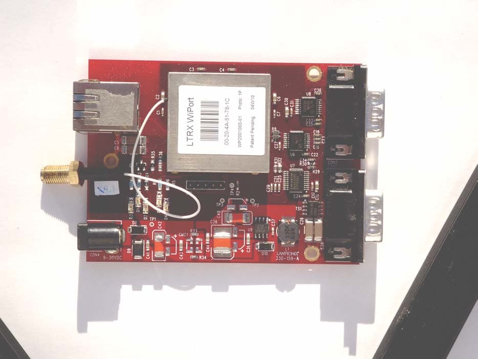
Click to zoom
Application Details
- Equipment Class
- DTS - Digital Transmission System
- Date of Grant
- Jan 11, 2005
- Application Purpose
- Original Equipment
- Date of Application
- Jan 11, 2005
- Equipment Note
- WiPort
- Frequency Range
- 2412.00000000 - 2462.00000000
- Company
- Lantronix, Inc.
- Country
- United States
Documents & Files
Document Text
Text extracted from the exhibit documents filed with the FCC. Open a document above to read the original.
Users Manual
WiPort™ User Guide Part Number 900-332 Revision C October 2004 WiPort™ User Guide 2 Copyright and Trademark © 2004, Lantronix. All rights reserved. No part of the contents of this book may be transmitted or reproduced in any form or by any means without the written permission of Lantronix. Printed in the United States of America. WiPort, with its patent-pending technology, is a trademark of Lantronix. Ethernet is a trademark of XEROX Corporation. UNIX is a registered trademark of The Open Group. Windows 95, Windows 98, Windows 2000, Windows NT, and Windows XP are trademarks of Microsoft Corp. Netscape is a trademark of Netscape Communications Corporation. Contacts Lantronix Corporate Headquarters 15353 Barranca Parkway Irvine, CA 92618, USA Phone: 949-453-3990 Fax: 949-453-3995 Technical Support Phone: 800-422-7044 or 949-453-7198 Fax: 949-450-7226 Online: www.lantronix.com/support Email [email protected] Sales Offices For a current list of our domestic and international sales offices, go to the Lantronix web site at http://www.lantronix.com/about/contact/ WiPort™ User Guide 3 Disclaimer and Revisions This equipment has been tested and found to comply with the limits for a Class B digital device, pursuant to Part 15 of the FCC Rules. These limits are designed to provide reasonable protection against harmful interference in a residential installation. This equipment generates, uses and can radiate radio frequency energy and, if not installed and used in accordance with the instructions, may cause harmful interference to radio communications. However, there is no guarantee that interference will not occur in a particular installation. If this equipment does cause harmful interference to radio or television reception, which can be determined by turning the equipment off and on, the user is encouraged to try to correct the interference by one of the following measures: Reorient or relocate the receiving antenna. Increase the separation between the equipment and receiver. Connect the equipment into an outlet on a circuit different from that to which the receiver is connected. Consult the dealer or an experienced radio/TV technician for help. This device complies with Part 15 of the FCC Rules. Operation is subject to the following two conditions: (1) This device may not cause harmful interference, and (2) this device must accept any interference received, including interference that may cause undesired operation. This device is intended only for OEM Integrators. The OEM integrator should be aware of the following important issues. Labeling of the End Product The end product integrate this module has to be clearly identified on the label that this end product contain an FCC approved RF module. The format of such statement could be "Contains Transmitter with FCC ID: R68WIPORT" or similar. Integration Note a) This module is authorized under limited module approval specified to mobile host equipment. So, the antenna must be installed such that 20cm is maintained between the antenna and users. b) The transmitter module may not be co-located with any other transmitter or antenna. As long as the 2 conditions above are met, further transmitter testing will not be required. However, the OEM integrator is still responsible for testing their end-product for any additional compliance requirements required with this module installed (for example, digital device emission, PC peripheral requirements, etc.) Note: In the event that these conditions can not be met (for example certain laptop configurations, general purpose PCMCIA or similar cards, or co- location with another transmitter), then the FCC authorization is no longer considered valid and the FCC ID can not be used on the final product (including the transmitter) and obtaining a separate FCC authorization. Note: Changes or modifications to this device not explicitly approved by Lantronix will void the user's authority to operate this device. WiPort™ User Guide 4 Contents Copyright and Trademark ________________________________________________ 2 Contacts______________________________________________________________ 2 Disclaimer and Revisions_________________________________________________ 3 1: Using This Guide 7 Purpose and Audience___________________________________________________ 7 Chapter Summary ______________________________________________________ 7 Additional Documentation ________________________________________________ 8 2: Introduction 9 Capabilities ___________________________________________________________ 9 Applications ___________________________________________________________ 9 Protocol Support ______________________________________________________ 10 Configuration Methods __________________________________________________ 10 Addresses and Port Numbers ____________________________________________ 10 Hardware Address __________________________________________________________ 10 IP Address ________________________________________________________________ 10 Port Numbers ______________________________________________________________ 11 3: Configuration Using DeviceInstaller 12 Accessing WiPort using DeviceInstaller_____________________________________ 12 Server Configuration ___________________________________________________ 12 WLAN Configuration ___________________________________________________ 13 Host List Configuration__________________________________________________ 14 OEM Pin Configuration _________________________________________________ 14 Channel 1 and Channel 2 Configuration ____________________________________ 15 Email Configuration ____________________________________________________ 19 4: Configuration using Web-Manager 20 Accessing WiPort using Web-Manager _____________________________________ 20 Network Configuration __________________________________________________ 21 Automatic IP Address Configuration ____________________________________________ 22 Static IP Address Configuration ________________________…
Text truncated - open the document above for the full version.
Cover Letter(s)
December 14, 2004 American TCB 6731 Whittier Ave., Suite C110 McLean, VA 22101 Gentlemen: The attached documentation is provided in support of a formal submission to your organization for a modular approval of an intentional unlicensed transmitter. On behalf of our client, Aegis Labs has included an application for a Grant of Equipment Authorization pursuant to Subpart C of part 15 of FCC Rules (47 CFR) regarding intentional radiators. The data within the test report demonstrates the equipment was tested in a manner described under Part 2 and 15 of the Code of Federal Regulations. This is a modular submittal for approval of the Wireless Embedded Device Server (MN: WiPort, FCC ID: R68WIPORT), which is a Wireless Embedded Device Server that provides a network-enabling solution based on the IEEE 802.11b wireless standard. WiPort allows Original Equipment Manufacturers (OEMs) to add wireless connectivity to their products by incorporating it onto a circuit board. It was tested as a standalone device with a HyperLink Technologies (PN: HG2403RD-RSF) antenna continuously transmitting and receiving form the antenna port. If there are any additional questions or if further information is needed, please contact us at your earliest convenience. Sincerely, Rick Candelas Aegis Labs, Inc. Lab Manager Enclosure (1 Emissions Test Report + Exhibits) AEGIS LABS, INC 22431 Antonio Parkway B160-417, Rancho Santa Margarita, CA 92688 949-459-7886 TEL 949-459-7869 FAX www.aegislabsinc.com
Cover Letter(s)
Modular Approval Request Letter Aegis Labs Inc. January 13, 2005 Dear Application Examiner, Lantronix Wireless Embedded Device Server, MN: WiPort, FCC ID: R68WIPORT, would like to have your authorization for Module Approval specific to the mobile device such as Access Point, Router, Notebook, and similar equipment. The requirements of Public Notice DA00-1407 have been met and shown on the following statements. 1. “The modular transmitter must have its own RF shielding.”: The radio portion of this module has been shielded, please see exhibition External Photo. 2. “The modular transmitter must have buffered modulation/data inputs.” The EUT has buffered data inputs; it is integrated in Agere device Hermes II WL60010. 3. “The modular transmitter must have its own power supply regulation.” There are regulators in the DC input port, the part number is LP3995ILDX, and PSC015. 4. “The modular transmitter must comply with the antenna requirements of section 15.203 and 15.204(C).” The EUT meets the FCC antenna requirements. The spurious emission, unique antenna connector and photo of antennas are shown in the test report and antenna information exhibit. 5. “The modular transmitter must be tested in a stand-alone configuration” The EUT was tested in a stand-alone configuration outside of the chassis. Please see the Photograph – Test Setup exhibit. 6. “The modular transmitter must be labeled with its own FCC ID number.” Please see the Label for Wiport exhibit for the FCC ID of this module. And also the Users Manual exhibit, there are instructions give to the OEM on how to label the end product. FCC ID: R68WIPORT Test Report No. LANTR-041213F 7. “The modular transmitter must comply with any specific rule or operating requirements applicable to the transmitter and the manufacturer must provide adequate instructions along with the module to explain any such requirements.” The EUT is compliant with all applicable FCC rules. Detail instructions for maintaining compliance are given in the Users Manual. 8. “The modular transmitter must comply with any applicable RF exposure requirements.” The EUT is compliant with all applicable RF exposure requirements. RF Exposure is addressed in the RF exposure exhibition. Please contact me if you have any further questions. Thanks for your attention. Best Regards, Rick Candelas / Manager Aegis Labs Inc. [email protected] 949-459-7886
Cover Letter(s)
Marketed as a Package Lantronix will market the WiPort module as everything that is in the shield where the label is located. The module will include the 802.11b transmitter circuit board and the controller board inside the shield and will only be marketed as a package. They will package it together with the controller board all enclosed in the shield? Rick Candelas Aegis Labs, Inc. Office 949.459.7886
External Photos
Top View Bottom View
Internal Photos
Top View “Transmitter Top Shield Removed” Top View “EUT with Transmitter Removed” Top View “Transmitter Close-up with Top Shield Removed” Bottom View “Transmitter Close-up” Top View “Transmitter Board” Top View “Transmitter Board, Shield Removed” Bottom View “Transmitter Board With Insulation” Bottom View “Transmitter Board Without Insulation” Top View “Transmitter Daughter Board” Bottom View “Transmitter Daughter Board With Insulation” Bottom View “Transmitter Daughter Board Without Insulation” Top View “Lower Shield” Bottom View “Upper Shield”
RF Exposure Info
WiFi ANTENNAS Select By Frequency · 900 MHz · 1.9 GHz · 2.3 GHz · 2.4 GHz · 2.6 GHz · 4.9 GHz · 5.3 GHz · 5.8 GHz Wireless Audio/Video · 2.4 GHz Mobile Antennas · Antenna Kits · Mobile Mounts · Antennas Antenna Accessories · Antenna Mounting Kits Frequency Converters · 2.4 to 5.8 GHz 2-Way Main Menu · NEW PRODUCTS · Amplifiers · Antennas · Cable Products · Lightning Protectors · Connectors · Adapters · PoE · Wireless Kits · Signal Splitters · Frequency Converters · Signal Filters · Power Supplies · Tools · Accessories · Weatherproof Enclosures · OEM Products · Site Map · SPECIALS & SALE ITEMS · CLEARANCE ITEMS Ordering Info · My Cart · Order This compact 2.4GHz omnidirectional "rubber-duck" WiFi antenna provides broad coverage and 2.2 dBi gain. It is a coaxial sleeve design with an omni-directional pattern. It is ideally suited for IEEE 802.11b and 802.11g wireless LANs, Bluetooth® and other WLAN applications. Only 4.7" long, this flexible antenna features a tilt-and-swivel reverse-polarity SMA plug connector, allowing them to be used vertically, at a right angle, or any angle in-between. It is suitable as a replacement antenna for many access points and radios that are equipped with reverse-polarity SMA connectors including D-Link®, Linksys® WET11 and others (Note: This RF antenna is used as a "replacement" antenna rather than a "range extender" antenna. It should yield similar range to most radio's stock antennas) Electrical Specifications Mechanical Specifications 2.4 GHz 2.2 dBi Reverse Polarity SMA "Rubber Duck" Wireless LAN Antenna HyperGain® HG2402RD-RSF z Compact size, only 4.7" long z Tilt and swivel design z RP-SMA Connector z 802.11b, 802.11g and Bluetooth® compatible Features Order Part Number Wholesale-Direct Pricing Buy Online HG2402RD-RSF Quantity 1-4: $6.95 each Quantity 5-9: $6.45 each Quantity 10+: $6.25 each Description Specifications Frequency 2400-2500 MHz Gain 2.2 dBi Impedance 50 Ohm VSWR < 2.0 Weight 0.52 oz. (15 g) Length 4.7" (105 mm) Diameter 0.4" (10 mm) Finish Matte Black Connector Reverse Polarity SMA Plug Operating Temperature -40° C to to 85° C (-40° F to 185° F) Polarization Vertical Page 1 of 22.4 GHz 2.2 dBi RP-TNC Rubber Duck 802.11b 802.11g Wireless LAN and Bluetooth® Compatible Wi-Fi... 12/10/2004http://www.hyperlinktech.com/web/hg2402rd_rsf.php Antenna Gain Pattern Guaranteed Quality This product is backed by Hyperlink's Limited Warranty Email Us • tel: 561-995-2256 • fax: 561-995-2432 hours: 9:00am - 7:00pm EST contact us | support | privacy policy | site map | copyright © 2004 HyperLink Technologies, Inc. All rights reserved. Page 2 of 22.4 GHz 2.2 dBi RP-TNC Rubber Duck 802.11b 802.11g Wireless LAN and Bluetooth® Compatible Wi-Fi... 12/10/2004http://www.hyperlinktech.com/web/hg2402rd_rsf.php
RF Exposure Info
MPE Calculations Systems operating under the provision of 47 CFR 1.1307(b)(1) shall be operated in a manor that ensures that the public is not exposed to radio frequency energy levels in excess of the FCC guidelines. The EUT will only be used with a separation of 20 centimeters or greater between the antenna and the body of the user or nearby persons and can therefore be considered a mobile transmitter per 47 CFR 2.1091(b). The MPE calculation for this exposure is shown below. Using the Antennas with highest output power: The peak radiated output power (EIRP) is calculated as follows: Antenna Frequency (GHz) Power input to the antenna (P) (dBm) Power gain of the antenna (G) (dBi) EIRP (P+G) (dBm) EIRP Log -1(dBm/10) (mW) HyperLink Technologies (PN: HG2403RD-RSF) 2.4 15.87 2.20 18.07 64.12 EIRP = P + G Where P = Power input to the antenna (mW). G = Power gain of the antenna (dBi) The numeric gain (G) of the antenna with a gain specified in dB is determined by: Antenna Frequency (GHz) Antenna Gain (G) (dBi) Numeric Antenna Gain Log -1(dBm/10) (dB) HyperLink Technologies (PN: HG2403RD-RSF) 2.4 2.20 1.66 G = Log -1 (dB antenna gain/10) Power density at the specific separation: Antenna Frequency (GHz) Power input to the antenna (P) (mW) Numeric Power Gain of the Antenna (G) (dB) Maximum Power Spectral Density S=PG/(4R 2 π) (mW/cm 2 ) Maximum Power Spectral Density Limit (mW/cm 2 ) HyperLink Technologies (PN: HG2403RD-RSF) 2.4 38.64 1.66 0.013 1.00 S = PG/(4R 2 π) Where S = Maximum power density (mW/cm 2 ) P = Power input to the antenna (mW). G = Numeric power gain of the antenna R = Distance to the center of the radiation of the antenna (20cm = limit for MPE) The maximum permissible exposure (MPE) for the general population is 1mW/cm 2 . The power density at 20cm does not exceed the 1mW/cm 2 limit. Therefore, the exposure condition is compliant with FCC rules.
Test Report
Page 1 of 17 Report Number: LANTR-041213F FCC ID: R68WIPORT Modular Approval Test Report And Application for Grant of Equipment Authorization Pertaining To: EUT FCC ID: Wireless Embedded Device Server, Model: WiPort R68WIPORT Configuration 802.11b module with a HyperLink Technologies Antenna MEASUREMENTS PERFORMED IN ACCORDANCE WITH Regulatory Standard(s) 47 CFR Part 15, Subpart C Section 15.247 Test Method: ANSI C63.4: 2001 American National Standard for Methods of Measurement of Radio-Noise Emissions from Low- Voltage Electrical and Electronic Equipment in the Range of 9 kHz to 40 GHz Certificate Number: 1111.01 APPLICANT: PREPARED BY: Lantronix, Inc. Aegis Labs, Inc. 15353 Barranca Parkway 22431 Antonio Parkway B160-417 Irvine, California 92618 Rancho S. Margarita, CA 92688 Contact(s): Trish Selbo Agent(s): Mr. Steve Kuiper Mr. Rick Candelas Test Report #: LANTR-041213F APPENDICES REPORT BODY A TOTAL PAGES PAGES 17 31 48 Test Report Revision: None The contents of this report shall not be reproduced except in full, without the written approval of Aegis Labs, Inc. Page 2 of 17 Report Number: LANTR-041213F FCC ID: R68WIPORT TABLE OF CONTENTS SECTION TITLE PAGE COVER SHEET.................................................................................... 01 TABLE OF CONTENTS............................................................................................... 02 1.0 CERTIFICATION OF TEST DATA............................................................................. 03 2.0 SUMMARY OF TEST RESULTS.............................................................. 04 3.0 ADMINISTRATIVE DATA AND TEST DESCRIPTION.......................................... 05 4.0 DESCRIPTION OF EUT..................................................................................... 06 4.1 EUT Description..................................................................................... 06 4.1.1 Channel Number and Frequencies................................................................ 07 4.2 EUT Configuration.................................................................................. 08 4.3 List of EUT Sub-Assemblies and Host Equipment...................................................... 09 4.4 I/O Cabling Diagram and Description............................................................................. 10 5.0 TEST EQUIPMENT AND TEST SETUPS............................................................... 12 5.1 AC Power Line Conducted Emissions............................................................ 12 5.2 Spurious Radiated Emissions...................................................................... 13 5.3 Conducted Emissions At The Antenna Port.................................................................... 13 5.4 Test and Measurement Equipment Used......................................................... 14 6.0 SAMPLE CALCULATIONS.......................................................................................... 15 7.0 MODIFICATIONS AND RECOMMENDATIONS........................................ 17 APPENDICES A Test Data Page 3 of 17 Report Number: LANTR-041213F FCC ID: R68WIPORT 1.0 CERTIFICATION OF TEST DATA Aegis Labs, Inc. operates as both a Nevada and California Corporation with no organizational or financial relationship with any company, institution, or private individual. Testing and engineering functions provided by Aegis Labs are furnished through the use of part-time, full-time or consulting engineers with the appropriate qualifications to carry out their duties. The intended purpose of this test report is to describe the measurement procedure and to determine whether the equipment under test “EUT” complies with both the conducted and radiated limits. Limits for emissions testing are described under Subpart C of Part 15 of the FCC rules. The data, data evaluation and equipment configuration represented herein are a true and accurate representation of the Equipment Under Test (EUT) under the requirements specified in the emissions standard as described below. The test results contained in this report are only representative of the test sample tested as described in Section 3.0 of this report. Certification of the EUT is required as a prerequisite to marketing as defined in Part 2 of the FCC Rules. Prepared By: ________________________12/20/04 Rick Candelas Date: Staff Engineer Aegis Labs, Inc. Report Approved By: ________________________12/20/04 Steve J. Kuiper Date: Quality Assurance Manager Aegis Labs, Inc. Page 4 of 17 Report Number: LANTR-041213F FCC ID: R68WIPORT 2.0 SUMMARY OF TEST RESULTS The test results provided within this report, indicate that the EUT has been found to be in COMPLIANCE with the test specifications based upon the following RF compliance standards: Pass/Fail determination is based upon the nominal values of the test data. 802.11b Mode (2400-2483.5 MHz) EMISSIONS STANDARD FCC Part 15 Section Description Results Comments 15.247(a)(2) The minimum 6dB bandwidth shall be at least 500 kHz. PASSED 2412 MHz = 12.17 MHz 2437 MHz = 12.08 MHz 2462 MHz = 12.17 MHz 15.247(b)(1) The maximum peak output power of the intentional radiator shall not exceed 1 watt. PASSED 2412 MHz = 15.87 dBm = 38.64 mW 2437 MHz = 15.56 dBm = 35.97 mW 2462 MHz = 15.53 dBm = 35.73 mW 15.247(b)(4) The intentional radiator shall be operated in a manner that ensures that the public is not exposed to radio frequency energy levels in excess of the FCC guidelines per Section 1.1307(b)(1). PASSED Refer to MPE Calculations Exhibit 15.247(c) In any 100 kHz bandwidth outside the frequency band in which the spread spectrum intentional radiator is operating, the radio frequency power that is produced by the intentional radiator shall be at least 20 dB below that in the 100 kHz bandwidth within the band that contains the highest level of the desired power. PASSED See Data Sheets 15.247(c) Radiated emissions, which fall in the restricted bands, as defined in Sec. 15.205(a), must also comply …
Text truncated - open the document above for the full version.
Test Setup Photos
Maximum Peak Output Power Measurement Setup Conducted Emissions at Antenna Terminal Setup AC Conducted Emissions Measurement (Front View) Setup AC Conducted Emissions Measurement (Rear View) Setup Radiated Emissions Measurement (Front View) Setup Radiated Emissions Measurement (Rear View) Setup
Contact Information
Applicant
Eric Bass(VP of Engineering)
Technical Contact
Aegis Labs, Inc.Rick Candelas
[email protected]949-459-7886
23091 Antonio Parkway, #B160-417 · Rancho Santa Margarita, California · United States
Test Firm
AEGIS Labs, Inc.Steve Kuiper
Technical Specifications
| # | Rule Parts | Frequency Range | Power Output |
|---|---|---|---|
| 1 | 15C | 2.41 GHz - 2.46 GHz | 39.00 mW |
Other Applications from Lantronix, Inc.
R68FOX5BT
Aug 27, 2026FOX5 Series
Equipment Class
DSS - Part 15 Spread Spectrum TransmitterR68XPICO600
Apr 08, 2026Wi-Fi & Bluetooth Module
Equipment Class
NII - Unlicensed National Information Infrastructure TXR68OQ8550
Mar 04, 2026Open-Q 8550CS SOM
Equipment Class
DTS - Digital Transmission SystemR68OQ2200S
Jul 17, 2024Wireless Module
Equipment Class
DTS - Digital Transmission System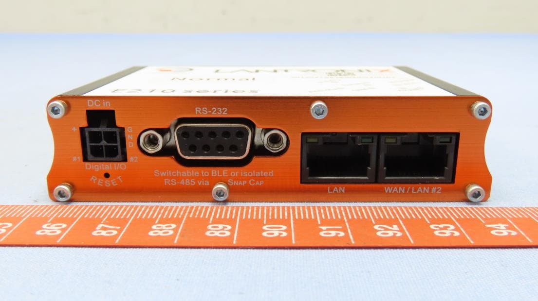
R68E213W
Nov 21, 2022E210 Series
Equipment Class
DTS - Digital Transmission System