R68WIPORTGWIRELESS EMBEDDED DEVICE SERVER
Lantronix, Inc.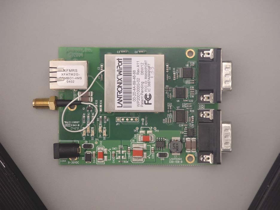
Click to zoom
Application Details
- Equipment Class
- DTS - Digital Transmission System
- Date of Grant
- Jun 20, 2006
- Application Purpose
- Original Equipment
- Date of Application
- Jun 20, 2006
- Equipment Note
- WIRELESS EMBEDDED DEVICE SERVER
- Frequency Range
- 2412.00000000 - 2462.00000000
- Company
- Lantronix, Inc.
- Country
- United States
Documents & Files
Document Text
Text extracted from the exhibit documents filed with the FCC. Open a document above to read the original.
Users Manual
WiPort™ Integration Guide Part Number 900-333 Revision G June 2006 Copyright and Trademark © 2005, 2006, Lantronix. All rights reserved. No part of the contents of this book may be transmitted or reproduced in any form or by any means without the written permission of Lantronix. Printed in the United States of America. WiPort, with its patent-pending technology, is a trademark of Lantronix. Ethernet is a trademark of XEROX Corporation. UNIX is a registered trademark of The Open Group. Windows 95, Windows 98, Windows 2000, Windows NT, and Windows XP are trademarks of Microsoft Corp. Netscape is a trademark of Netscape Communications Corporation. Contacts Lantronix Corporate Headquarters 15353 Barranca Parkway Irvine, CA 92618, USA Phone:949-453-3990 Fax: 949-453-3995 Technical Support Phone: 800-422-7044 or 949-453-7198 Fax: 949-450-7226 Online: www.lantronix.com/support Email [email protected] Sales Offices For a current list of our domestic and international sales offices, go to the Lantronix web site at www.lantronix.com/about/contact/ WiPort™ Integration Guide 3 Disclaimer This equipment has been tested and found to comply with the limits for a Class B digital device, pursuant to Part 15 of the FCC Rules. These limits are designed to provide reasonable protection against harmful interference in a residential installation. This equipment generates, uses and can radiate radio frequency energy and, if not installed and used in accordance with the instructions, may cause harmful interference to radio communications. However, there is no guarantee that interference will not occur in a particular installation. If this equipment does cause harmful interference to radio or television reception, which can be determined by turning the equipment off and on, the user is encouraged to try to correct the interference by one of the following measures: Reorient or relocate the receiving antenna. Increase the separation between the equipment and receiver. Connect the equipment into an outlet on a circuit different from that to which the receiver is connected. Consult the dealer or an experienced radio/TV technician for help. This device complies with Part 15 of the FCC Rules. Operation is subject to the following two conditions: (1) This device may not cause harmful interference, and (2) this device must accept any interference received, including interference that may cause undesired operation. This device is intended only for OEM Integrators. The OEM integrator should be aware of the following important issues. Labeling of the End Product The end product to integrate this module has to be clearly identified on the label that this end product contains an FCC approved RF module. The format of such statement could be "Contains Transmitter with FCC ID: R68WIPORTG" or similar. Integration Note a) This module is authorized under limited module approval specified to mobile host equipment. So, the antenna must be installed such that 20cm is maintained between the antenna and users. b) The transmitter module may not be co-located with any other transmitter or antenna. As long as the 2 conditions above are met, further transmitter testing will not be required. However, the OEM integrator is still responsible for testing their end-product for any additional compliance requirements required with this module installed (for example, digital device emission, PC peripheral requirements, etc.) Note: In the event that these conditions can not be met (for example certain laptop configurations, general purpose PCMCIA or similar cards, or co- location with another transmitter), then the FCC authorization is no longer considered valid and the FCC ID can not be used on the final product (including the transmitter) and obtaining a separate FCC authorization. Note: Changes or modifications to this device not explicitly approved by Lantronix will void the user's authority to operate this device. WiPort™ Integration Guide 4 Contents 1: Introduction 6 About the Integration Guide________________________________________________6 Additional Documentation _________________________________________________6 2: Description and Specifications 7 WiPort Overview ________________________________________________________7 WiPort Block Diagram ____________________________________________________8 PCB Interface __________________________________________________________9 Mating Connector ______________________________________________________10 Serial Input/Output______________________________________________________10 Sample Layouts for RS-485 Connectivity ____________________________________12 WLAN Input/Output _____________________________________________________13 Ethernet Input/Output ___________________________________________________13 Power, Ground, and Reset _______________________________________________14 Absolute Maximum Ratings_______________________________________________14 Recommended Operating Conditions _______________________________________14 Ethernet PHY Receiver Input Characteristics (RX+, RX-) ________________________15 100Base-TX Transceiver Characteristics (TX+, TX-) ___________________________15 Wireless Specifications __________________________________________________15 Technical Specifications _________________________________________________17 Dimensions ___________________________________________________________18 Recommended PCB Layout ______________________________________________19 Product Information Label ________________________________________________20 3: Development Kit 21 Contents of the Kit ______________________________________________________21 Evaluation Board Description _____________________________________________21 Serial Interfaces________________________________________________________21 Power Supply _________________________________________________________22 General Control PLD ____________________________________________________22 Configuration Switch Bank ________________________…
Text truncated - open the document above for the full version.
Users Manual
WiPort™ User Guide Part Number 900-332 Revision H June 2006 WiPort™ User Guide 2 Copyright and Trademark © 2005, 2006, Lantronix. All rights reserved. No part of the contents of this book may be transmitted or reproduced in any form or by any means without the written permission of Lantronix. Printed in the United States of America. WiPort, with its patent-pending technology, is a trademark of Lantronix. Ethernet is a trademark of XEROX Corporation. UNIX is a registered trademark of The Open Group. Windows 95, Windows 98, Windows 2000, Windows NT, and Windows XP are trademarks of Microsoft Corp. Netscape is a trademark of Netscape Communications Corporation. Contacts Lantronix Corporate Headquarters 15353 Barranca Parkway Irvine, CA 92618, USA Phone: 949-453-3990 Fax: 949-453-3995 Technical Support Phone: 800-422-7044 or 949-453-7198 Fax: 949-450-7226 Online: www.lantronix.com/support Email [email protected] Sales Offices For a current list of our domestic and international sales offices, go to the Lantronix web site at http://www.lantronix.com/about/contact/ WiPort™ User Guide 3 Disclaimer and Revisions This equipment has been tested and found to comply with the limits for a Class B digital device, pursuant to Part 15 of the FCC Rules. These limits are designed to provide reasonable protection against harmful interference in a residential installation. This equipment generates, uses, and can radiate radio frequency energy and, if not installed and used in accordance with the instructions, may cause harmful interference to radio communications. However, there is no guarantee that interference will not occur in a particular installation. If this equipment does cause harmful interference to radio or television reception, which can be determined by turning the equipment off and on, the user is encouraged to try to correct the interference by one of the following measures: Reorient or relocate the receiving antenna. Increase the separation between the equipment and receiver. Connect the equipment into an outlet on a circuit different from that to which the receiver is connected. Consult the dealer or an experienced radio/TV technician for help. This device complies with Part 15 of the FCC Rules. Operation is subject to the following two conditions: (1) This device may not cause harmful interference, and (2) this device must accept any interference received, including interference that may cause undesired operation. This device is intended only for OEM Integrators. The OEM integrator should be aware of the following important issues. Labeling of the End Product The end product to integrate this module has to be clearly identified on the label that this end product contains an FCC approved RF module. The format of such statement could be "Contains Transmitter with FCC ID: R68WIPORTG" or similar. Integration Note a) This module is authorized under limited module approval specified to mobile host equipment. So, the antenna must be installed such that 20cm is maintained between the antenna and users. b) The transmitter module may not be co-located with any other transmitter or antenna. As long as the two conditions above are met, further transmitter testing will not be required. However, the OEM integrator is still responsible for testing their end product for any additional compliance requirements required with this module installed (for example, digital device emission, PC peripheral requirements, etc.) Note: In the event that these conditions can not be met (for example certain laptop configurations, general purpose PCMCIA or similar cards, or co- location with another transmitter), then the FCC authorization is no longer considered valid and the FCC ID can not be used on the final product (including the transmitter) and obtaining a separate FCC authorization. Note: Changes or modifications to this device not explicitly approved by Lantronix will void the user's authority to operate this device. WiPort™ User Guide 4 Contents Copyright and Trademark _________________________________________________2 Contacts ______________________________________________________________2 Disclaimer and Revisions _________________________________________________3 1: Using This Guide 8 Purpose and Audience ___________________________________________________8 Chapter Summary _______________________________________________________8 Additional Documentation _________________________________________________9 2: Introduction 10 Capabilities ___________________________________________________________10 Applications ___________________________________________________________11 Protocol Support _______________________________________________________11 Configuration Methods __________________________________________________11 Addresses and Port Numbers _____________________________________________11 Hardware Address __________________________________________________________11 IP Address_________________________________________________________________12 Port Numbers ______________________________________________________________12 3: Using DeviceInstaller 13 Accessing WiPort using DeviceInstaller _____________________________________13 Viewing the WiPort’s Current Configuration __________________________________14 4: Configuration Using Web-Manager 17 Accessing WiPort Web-Manager using DeviceInstaller__________________________17 Network Configuration ___________________________________________________17 Automatic IP Address Configuration _____________________________________________18 Static IP Address Configuration ________________________________________________18 Server Configuration ____________________________________________________19 Host List Configuration __________________________________________________20 Channel 1 and Channel 2 Configuration _____________________________________21 Serial Settings ______________________________________________________________21 Connection Settings - TCP ______________…
Text truncated - open the document above for the full version.
Attestation Statements
Ll\NT~NIX@ 15353BarrancaParkway IrvineI CA 92618I USA Tel:949.453.399° DateJune1, 2006 Fax:949.453.3995 EquipmentAuthorizationDivision FederalCommunicationsCommission 7435OaklandMillsRoad Columbia,MD21046 www.lantronix.com ToWhomIt MayConcern: PleasebeadvisedthattheFrequencyRangelisted2.412GHzto2.472GHzis correct duetothisdeviceFCCID:R68WIPORTG,modelnumber:WiPortbeingmarketed globally.Thisdevicewillbelimitedtochannels1 to11,frequencies2.412GHzto2.462 GHzin theU.S.Thetransmittedlevelis alsofixedto14dBm+1.5dBm/-1.0dBmmax. TheseparametersaredonebytheabilitytoprogramtheinternalFLASHIntegrated CircuitfortheU.S.SKUmakingthisdeviceonlyoperateonthesechannels,frequency range,andtransmittedlevel.Theenduserwillnothavetheabilitytochangethese deviceparametersbeyondwhatis allowablein theU.S. Thankyouforyourattentiontothismatter. If youhaveanyfurtherquestionsorneedadditionalinformation,pleasefeelfreetogive mea call. / Dated this 01 DayofJune 2006 By:~Je/bti Signature PatriciaSelbo Printed Title:DirectorofProgramManagement Onbehalfof: Lantronix Telephone:949-450-9832
Attestation Statements
TRANSMITTER MODULAR APPROVAL ATTESTATION June 8, 2006 Federal Communications Commission Re: Application Modular Approval Certification for FCC ID: R68WIPORTG Gentlemen: The following attestation addresses the eight requirements to support modular approval as required by the FCC Public Notice DA00-1407 “Part 15 Unlicensed Modular Transmitter Approval” 1 The modular transmitter has its own RF shielding and does not rely upon the shielding provided by the device into which it is installed in order to comply with Part 15 limits. 2 The modular transmitter has buffered modulation/data inputs. All inputs to the modules are buffered through the radio circuitry. 3 The modular transmitter has its own power supply regulator. 4 The modular transmitter has an antenna that complies with section 15.203 and 15.204(c) of the FCC rules. It has a Reverse Polarity-SMA type of connector at the transmitter end and is soldered to the antenna (depending on OEM configuration). The antenna used with the module was tested with the module. 5 The modular transmitter was tested in a stand-alone configuration without a chassis during testing to show compliance with Part 15 emission limits. The transmitter module complies with the AC line conducted requirements found in Section 15.207. AC power lines. 6 The modular transmitter will be labeled with its own FCC ID. Also, the OEM host manufacturer will be informed to display a label referring to the enclosed module. The exterior label will read as follows: “Contains Transmitter Module FCC ID: XYZMODEL1” or “Contains FCC ID: XYZMODEL1”. 7 The modular transmitter is manufactured so that the user cannot influence the operation of the transmitter that will operate outside of the scope of the regulations. 8 The modular transmitter meets the MPE calculations of 47 CFR 1.1307(b)(1). If there are any additional questions or if further information is needed, please contact us at your earliest convenience at (949) 459-7886. Sincerely, Johnny Candelas Aegis Labs, Inc. Test Technician
Cover Letter(s)
July 7, 2006 TIMCO Engineering Inc. 849 NW State Road 45 Newberry, Florida 32669 Gentlemen: The attached documentation is provided in support of a formal submission to your organization for a modular approval of an intentional unlicensed transmitter. On behalf of our client, Aegis Labs has included an application for a Grant of Equipment Authorization pursuant to Subpart C of part 15 of FCC Rules (47 CFR) regarding intentional radiators. The data within the test report demonstrates the equipment was tested in a manner described under Part 2 and 15 of the Code of Federal Regulations. This is a modular submittal for approval of the Wireless Embedded Device Server (MN: WiPort-XX, FCC ID: R68WIPORTG), which is a Wireless Embedded Device Server that provides a network-enabling solution based on the IEEE 802.11b/g wireless standard. WiPort allows Original Equipment Manufacturers (OEMs) to add wireless connectivity to their products by incorporating it onto a circuit board. It was tested as a standalone device with a US Robotics (PN: USR5481) antenna continuously transmitting and receiving form the antenna port. If there are any additional questions or if further information is needed, please contact us at your earliest convenience. Sincerely, Johnny Candelas Aegis Labs, Inc. Test Technician Enclosure (1 Emissions Test Report + Exhibits)
External Photos
Top View Bottom View
Internal Photos
Top View “Transmitter Top Shield Removed” Top View “EUT with Transmitter Removed” Top View “Transmitter Close-up with Top Shield Removed” Bottom View “Transmitter Close-up” Top View “Transmitter Board” Top View “Transmitter Board, Shield Removed” Bottom View “Transmitter Board With Insulation” Bottom View “Transmitter Board Without Insulation” Top View “Transmitter Daughter Board” Bottom View “Transmitter Daughter Board With Insulation” Bottom View “Transmitter Daughter Board Without Insulation” Top View “Lower Shield” Bottom View “Upper Shield”
RF Exposure Info
MPE Calculations Systems operating under the provision of 47 CFR 1.1307(b)(1) shall be operated in a manor that ensures that the public is not exposed to radio frequency energy levels in excess of the FCC guidelines. The EUT will only be used with a separation of 20 centimeters or greater between the antenna and the body of the user or nearby persons and can therefore be considered a mobile transmitter per 47 CFR 2.1091(b). The MPE calculation for this exposure is shown below. Using the Antennas with highest output power: The peak radiated output power (EIRP) is calculated as follows: Antenna Frequency (GHz) Power input to the antenna (P) (dBm) Power gain of the antenna (G) (dBi) EIRP (P+G) (dBm) EIRP Log -1(dBm/10) (mW) US Robotics (PN: USR5481) 2.4 21.08 5.00 26.08 405.51 EIRP = P + G Where P = Power input to the antenna (mW). G = Power gain of the antenna (dBi) The numeric gain (G) of the antenna with a gain specified in dB is determined by: Antenna Frequency (GHz) Antenna Gain (G) (dBi) Numeric Antenna Gain Log -1(dBm/10) (dB) US Robotics (PN: USR5481) 2.4 5.00 3.16 G = Log -1 (dB antenna gain/10) Power density at the specific separation: Antenna Frequency (GHz) Power input to the antenna (P) (mW) Numeric Power Gain of the Antenna (G) (dB) Maximum Power Spectral Density S=PG/(4R 2 π) (mW/cm 2 ) Maximum Power Spectral Density Limit (mW/cm 2 ) US Robotics (PN: USR5481) 2.4 128.23 3.16 0.081 1.00 S = PG/(4R 2 π) Where S = Maximum power density (mW/cm 2 ) P = Power input to the antenna (mW). G = Numeric power gain of the antenna R = Distance to the center of the radiation of the antenna (20cm = limit for MPE) The maximum permissible exposure (MPE) for the general population is 1mW/cm 2 . The power density at 20cm does not exceed the 1mW/cm 2 limit. Therefore, the exposure condition is compliant with FCC rules.
Test Report
Antenna Specifications USR5484 Key Applications - Connecting to 802.11b/802.11g wireless PCI cards to enhance range and to position the antenna away from the typically noisy behind-the-desktop location. Specifications & Standards: •Gain: 5dBi •Nominal Impedance: 50 Ohms •Frequency Range: 2.4 - 2.5 GHz •VSWR: 1.92 max. •Omni-directional •Desktop or magnetic base for vertical attachment •SMA straight plug reverse connector USR5481 Key Applications - Replacement antenna to extend the range of 802.11b/802.11g wireless routers, access points, and desktop adapters. Specifications & Standards: •Gain: 5dBi •Nominal Impedance: 50 Ohms •Frequency Range: 2.4 - 2.5 GHz •VSWR: 1.92 max. •Omni-directional •Direct swivel attachment •SMA plug reverse connector USR5482A Key Applications - Provides broad, focused coverage for 802.11b/802.11g wireless routers and access points in buildings with large coverage areas and wireless hot spots. Also for outdoor applications (e.g. building-to- building connections). Allows direct path with better pattern coverage. Specifications & Standards: •Gain: 9dBi •Nominal Impedance: 50 Ohms •Frequency Range: 2.4 - 2.5 GHz •VSWR: 1.92 max. •Polarization - Linear •Directional antenna •Wall or pole mountable •SMA plug reverse connector part number: R24.0527.00 U.S. Robotics and the U.S. Robotics logo are registered trademarks of U.S. Robotics Corporation. All rights reserved. USR5484 Scan Patterns USR5481 Scan Patterns USR5482A Scan Patterns
Test Report
Page 1 of 13 Report Number: LANTR-060321F Revision Number: NONE Modular Approval Test Report And Application for Grant of Equipment Authorization TEST REPORT PERTAINING TO: Equipment Under Test Model Number(s) Wireless Embedded Device Server WiPort CONFIGURATION 802.11g module with a US Robotics 5 dBi Antenna (USR5481) MEASUREMENTS PERFORMED IN ACCORDANCE WITH THE FOLLOWING STANDARD (S) Regulatory Standard(s) 47 CFR Part 15, Subpart C Section 15.247 Test Method: ANSI C63.4: 2003 American National Standard for Methods of Measurement of Radio-Noise Emissions from Low- Voltage Electrical and Electronic Equipment in the Range of 9 kHz to 40 GHz PREPARED FOR: PREPARED BY: Lantronix Inc. Aegis Labs, Inc. 15353 Barranca Parkway 22431 Antonio Parkway B160-417 Irvine, California 92618 Rancho S. Margarita, CA 92688 Contact(s): Mr. Daryl Miller Agent(s): Mr. Rick Candelas Mr. Johnny Candelas Test Report #: LANTR-060321F Test Report Revision: NONE APPENDICES REPORT BODY A B TOTAL PAGES PAGES 13 34 1 48 The contents of this report shall not be reproduced except in full, without the written approval of Aegis Labs, Inc. The Lantronix Inc. logo is used for identification purposes only and is a registered trademark of Lantronix Inc. Certificate Number: 1111.01 Page 2 of 13 Report Number: LANTR-060321F Revision Number: NONE TABLE OF CONTENTS SECTION TITLE PAGE COVER SHEET......................................................................................................... 01 TABLE OF CONTENTS.................................................................................................................... 02 1.0 REGULATORY COMPLIANCE GUIDELINES................................................................ 03 1.1 Guidelines For Testing To Emissions Standards..................................................................... 03 2.0 SUMMARY OF REGULATORY LIMITS.................................................................................. 04 3.0 ADMINISTRATIVE DATA AND TEST DESCRIPTION..................................................... 05 4.0 DESCRIPTION OF EUT CONFIGURATION....................................................................... 06 4.1 EUT Description ......................................................................................................... 06 4.2 EUT Configuration......................................................................................................................... 07 4.3 List of EUT Sub-Assemblies and Host Equipment........................................................................... 08 4.4 I/O Cabling Diagram and Description ................................................................................. 09 4.5 EMC Test Hardware and Software Measurement Equipment.............................................................. 11 5.0 CONDITIONS DURING EMISSIONS MEASUREMENTS................................................... 12 5.1 General..................................................................................................................... 12 5.2 Conducted Emissions Test Setup.......................................................................................................... 12 5.3 Radiated Emissions Test Setup......................................................................................... 13 APPENDICES A Test Data B Modifications And Recommendations Page 3 of 13 Report Number: LANTR-060321F Revision Number: NONE 1.0 REGULATORY COMPLIANCE GUIDELINES Aegis Labs, Inc. operates as both a Nevada and California Corporation with no organizational or financial relationship with any company, institution, or private individual. Testing and engineering functions provided by Aegis Labs were furnished by RF technicians and engineers with accredited qualifications and training credentials to carry out their duties. The object of this report was to publish verifiable test results of an EUT subjected to the tests outlined in the standard listed on the cover page of this report. 1.1 Guidelines For Testing To Emissions Standards This standard for EMC emission requirements apply to electrical equipment for Information Technology Equipment (ITE). Compliance to these standards and in combination with the other standards listed in this test report can be used to demonstrate presumption of compliance with the protection requirements of the appropriate agency standard. The purpose of this standard is to specify minimum requirements for emissions regarding electromagnetic compatibility (EMC) and protect the radio frequency spectrum 9 kHz. – 400 GHz. from unwanted interference generated from electrical/digital systems that intentionally or unintentionally generated RF energy. The emissions standards, normative documents and/or publications were used to conduct all tests performed on the equipment herein referred to as “Equipment Under Test”. Page 4 of 13 Report Number: LANTR-060321F Revision Number: NONE 2.0 SUMMARY OF TEST RESULTS 802.11g Mode (2400-2483.5 MHz) EMISSIONS STANDARD FCC Part 15 Section Description Results Comments 15.247(a)(2) The minimum 6dB bandwidth shall be at least 500 kHz. PASSED 2412 MHz = 16.50 MHz 2437 MHz = 16.58 MHz 2462 MHz = 16.58 MHz 15.247(b)(3) The maximum peak output power of the intentional radiator shall not exceed 1 watt. PASSED 2412 MHz = 20.81 dBm = 120.50 mW 2437 MHz = 20.93 dBm = 123.88 mW 2462 MHz = 20.23 dBm = 105.44 mW 15.247(b)(5) The intentional radiator shall be operated in a manner that ensures that the public is not exposed to radio frequency energy levels in excess of the FCC guidelines per Section 1.1307(b)(1). PASSED Refer to MPE Calculations Exhibit 15.247(c) In any 100 kHz bandwidth outside the frequency band in which the spread spectrum intentional radiator is operating, the radio frequency power that is produced by the intentional radiator shall be at least 20 dB below that in the 100 kHz bandwidth within the band that contains the highest level of the desired power. PASSED See Data …
Text truncated - open the document above for the full version.
Test Report
WiPort Data Sheet General Description WiPort Data Sheet Copyright© 2006, Lantronix. All rights reserved. The WiPort™ is the most compact, integrated solution available to add 802.11b/g wireless networking to any device with a serial or wired Ethernet interface. Using this highly integrated hardware and software platform, you will add to your bottom line by significantly reducing product development time, risk, and cost. The WiPort offers the highest level of integration available in a device server. Within a compact package is a DSTni™ x86 controller, memory, 802.11b/g radio, a 10/100 Ethernet transceiver, and dual high-speed serial ports. All of this combines to give you a complete networking solution. The WiPort is designed with flexibility to support additional wireless standards without requiring redesign. To enable access to a local network or the Internet, the WiPort integrates a fully developed TCP/IP network stack and OS. The WiPort also includes an embedded web server that can be used to remotely configure, monitor, or troubleshoot the attached device. WiPort serves web pages to a web browser when there is a need to gather information or communicate with networked devices. The WiPort becomes a conduit between you and your device over the network or Internet. The Windows™-based configuration software, Device Installer™, simplifies installation and setup. The WiPort can also be configured locally through its serial port, or remotely over a network using Telnet (password- protected) or a web browser. Flash memory provides for maintenance-free, nonvolatile storage of web pages, and allows future system software upgrades. Hardware & Software Description The WiPort functions independently of a PC, providing a complete hardware and software solution for adding wireless connectivity to your edge devices. Within a single package this powerful device server comes with an 802.11b wireless connection, a 10/100 Ethernet transceiver, a reliable and proven operating system stored in flash memory, an embedded web server, a full TCP/IP protocol stack, and WEP security. The WiPort software runs on a Lantronix DSTni controller which has 256 KB of internal SRAM, and 16 KB of boot ROM. The WiPort communicates to the edge device through a 3.3V logic level interface. 2 MB of flash memory is included for storing firmware and web pages. Key Features • Complete integrated RoHS compliant solution • Supports 802.11 WLAN or Ethernet connectivity • Serial to 802.11b/g conversion • Wired Ethernet to 802.11 b/g WLAN Bridging • Stable, field proven TCP/IP protocol suite and web- based application framework • Optional End-to-End 128, 192 and 256 Bit AES Encryption • WPA PSK TKIP security, 128 bit WEP encryption • Dual serial ports • Easy configuration through a web interface • Easy installation of customized web pages • Embedded web server • 11 General Purpose Input/Output (GPIO) pins • E-mail alerts • Upgradeable firmware via the network or serial port • High performance data throughput The WiPort runs on a single 3.3V supply, and has a built-in voltage supervisory circuit. The WiPort will connect through a coaxial cable “pigtail” to a panel-mounted external antenna, which makes the electro-mechanical integration very simple. Protocol Support The WiPort uses the widely accepted 802.11g protocol to connect to a wireless infrastructure or ad-hoc network, and is fully backward compatible with legacy 802.11b wireless networks. It uses the Transmission Control Protocol (TCP) to assure that no data is lost or duplicated and that everything sent to the connection arrives correctly at the target. Other supported protocols are listed …
Text truncated - open the document above for the full version.
Contact Information
Applicant
Eric Bass(VP of Engineering)
Test Firm
AEGIS Labs, Inc.Steve Kuiper
Technical Specifications
| # | Rule Parts | Frequency Range | Power Output |
|---|---|---|---|
| 1 | 15C | 2.41 GHz - 2.46 GHz | 128.20 mW |
Other Applications from Lantronix, Inc.
R68FOX5BT
Aug 27, 2026FOX5 Series
Equipment Class
DSS - Part 15 Spread Spectrum TransmitterR68XPICO600
Apr 08, 2026Wi-Fi & Bluetooth Module
Equipment Class
NII - Unlicensed National Information Infrastructure TXR68OQ8550
Mar 04, 2026Open-Q 8550CS SOM
Equipment Class
DTS - Digital Transmission SystemR68OQ2200S
Jul 17, 2024Wireless Module
Equipment Class
DTS - Digital Transmission System
R68E213W
Nov 21, 2022E210 Series
Equipment Class
DTS - Digital Transmission System