R68XSDRWLSGDRIG WIRELESS DEVICE SERVER
Lantronix, Inc.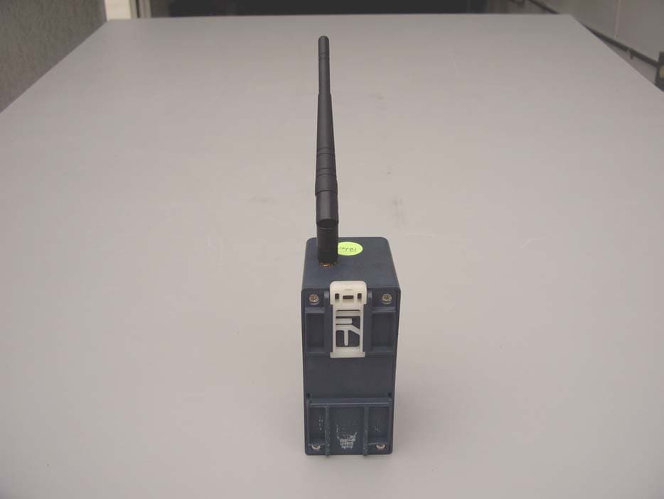
Click to zoom
Application Details
- Equipment Class
- DTS - Digital Transmission System
- Date of Grant
- Oct 22, 2006
- Application Purpose
- Original Equipment
- Date of Application
- Oct 22, 2006
- Equipment Note
- DRIG WIRELESS DEVICE SERVER
- Frequency Range
- 2412.00000000 - 2462.00000000
- Company
- Lantronix, Inc.
- Country
- United States
Documents & Files
Document Text
Text extracted from the exhibit documents filed with the FCC. Open a document above to read the original.
Users Manual
Part Number 900-422 Revision B October 2006 XPress DR+ User Guide XPress DR+ User Guide 2 Copyright & Trademark © 2006, Lantronix. All rights reserved. No part of the contents of this book may be transmitted or reproduced in any form or by any means without the written permission of Lantronix. Printed in the United States of America. Ethernet is a trademark of XEROX Corporation. UNIX is a registered trademark of The Open Group. Windows 95, Windows 98, Windows 2000, and Windows NT are trademarks of Microsoft Corp. Netscape is a trademark of Netscape Communications Corporation. Contacts Lantronix Corporate Headquarters 15353 Barranca Parkway Irvine, CA 92618, USA Phone: 949-453-3990 Fax: 949-453-3995 Technical Support Online: www.lantronix.com/support Sales Offices For a current list of our domestic and international sales offices, go to the Lantronix web site at www.lantronix.com/about/contact . Disclaimer & Revisions Operation of this equipment in a residential area is likely to cause interference, in which case the user, at his or her own expense, will be required to take whatever measures may be required to correct the interference. Attention: This product has been designed to comply with the limits for a Class A digital device pursuant to Part 15 of FCC Rules. These limits are designed to provide reasonable protection against such interference when operating in a commercial environment. This equipment generates, uses, and can radiate radio frequency energy, and if not installed and used in accordance with this guide, may cause harmful interference to radio communications. This Class A digital apparatus complies with Canadian ICES-003. Cet appareil num′erique de la classe A est conforme ′a la norme NMB-003 du Canada. Changes or modifications to this device not explicitly approved by Lantronix will void the user's authority to operate this device. The information in this guide may change without notice. The manufacturer assumes no responsibility for any errors that may appear in this guide. Date Rev. Comments 3/06 A Initial document 10/06 B Added description of wireless functionality XPress DR+ User Guide 3 Contents Chapter 1: Using This Guide 10 Purpose and Audience_______________________________________________ 10 Summary of Chapters _______________________________________________ 10 Additional Documentation ____________________________________________ 11 Chapter 2: Introduction 12 Product Description _________________________________________________ 12 Industrial Automation Protocols ________________________________________ 14 Network Protocols (Serial Tunneling)____________________________________ 14 XPress DR+ Application Examples _____________________________________ 15 Addresses and Port Numbers _________________________________________ 16 Hardware Address ______________________________________________________ 16 IP Address ____________________________________________________________ 16 Port Numbers __________________________________________________________ 16 Configuration Methods _______________________________________________ 17 Chapter 3: Installation and Hardware 18 What's in the Box? __________________________________________________ 18 What Must the User Provide? _____________________________________________ 18 Physically Connecting the XPress DR+ __________________________________ 18 XPress DR+ Front Panel _____________________________________________ 19 Serial Interface_____________________________________________________ 20 Screw Terminal Serial Connectors__________________________________________ 21 9-Pin RS-232 to Serial RJ45 Cable (P/N 500-103) _____________________________ 22 Ethernet Interface __________________________________________________ 23 Multi-Drop Ethernet Connections ___________________________________________ 23 Power Requirements ________________________________________________ 24 Reset Switch ______________________________________________________ 24 LEDs ____________________________________________________________ 25 Dimensions _______________________________________________________ 26 Wall Mount Bracket _________________________________________________ 27 Product Information Label ____________________________________________ 27 Chapter 4: XPress DR+W 28 Application Examples________________________________________________ 28 Serial Tunneling – Network _______________________________________________ 28 Chapter 1: Using This Guide XPress DR+ User Guide 4 Ad Hoc Network ________________________________________________________ 29 Serial Tunneling – Infrastructure ___________________________________________ 29 Ad Hoc XPress DR+W Connection _________________________________________ 30 Physically Connecting the XPress DR+W ________________________________ 30 Front Panel Description ______________________________________________ 31 LEDs ____________________________________________________________ 33 Required Information for Initial Configuration______________________________ 33 Hardware Address ______________________________________________________ 33 IP Address ____________________________________________________________ 33 WLAN Settings _________________________________________________________ 34 Installing the XPress DR+W for Initial Configuration ________________________ 34 Server Configuration (Option 0) ________________________________________ 34 Network Mode (XPress DR+W only) ________________________________________ 35 IP Address ____________________________________________________________ 35 Set Gateway IP Address _________________________________________________ 35 Netmask: Number of Bits for Host Part ______________________________________ 35 Change Telnet Configuration Password _____________________________________ 36 Change DHCP Device Name: _____________________________________________ 36 WLAN Configuration (Option 4) ________________________________________ 36 Topology______________________________________________________________ 37 Network Nam…
Text truncated - open the document above for the full version.
Attestation Statements
lI\NT~ONIX@ 15353BarrancaParkway IrvineI CA92618I USA Tel:949-453.3990 DateJune1, 2006 Fax:949.453.3995 www.lantronix.com EquipmentAuthorizationDivision FederalCommunicationsCommission 7435OaklandMillsRoad Columbia,MD21046 Anti-DruQAbuseAttestation PleaseacceptthisletterasanattestationonbehalfofLantronix,Inc.thattothebestof ourknowledge,information,andbehalf,noneofourofficers,directors,orpersons holding5%ormoreoftheoutstandingstockshares,votingornon-voting,havebeen deniedfederalbenefitsundersection5301of theAnti-DrugAbuseActof1988.21U.S.C. 853(a). If youhaveanyfurtherquestionsorneedadditional'jnformation,pleasefeelfreetogive mea callat 949-450-9832.':':~,. Dated this 01 DayofJune 2006 / ~<0b() Signature Patricia$elbo Printed By: Title:Dir.OfProgramManagement Onbehalfof:Lantronix Telephone:949-450-9832
Cover Letter(s)
August 1, 2006 TIMCO Engineering Inc. 849 NW State Road 45 Newberry, Florida 32669 Gentlemen: The attached documentation is provided in support of a formal submission to your organization for a mobile approval of an intentional unlicensed transmitter. On behalf of our client, Aegis Labs has included an application for a Grant of Equipment Authorization pursuant to Subpart C of part 15 of FCC Rules (47 CFR) regarding intentional radiators. The data within the test report demonstrates the equipment was tested in a manner described under Part 2 and 15 of the Code of Federal Regulations. This is a submittal for mobile approval of the DRIG Wireless Device Server (MN: XSDR22W00-01, FCC ID: R68XSDRWLSG), which is a Wireless Device Server that provides a network-enabling solution based on the IEEE 802.11b/g wireless standard. It was tested as a standalone device with a Wanshih 2.89 dBi Antenna (PN: WSS003) continuously transmitting and receiving form the antenna port. If there are any additional questions or if further information is needed, please contact us at your earliest convenience. Sincerely, Johnny Candelas Aegis Labs, Inc. Test Technician Enclosure (1 Emissions Test Report + Exhibits)
External Photos
Front View Back View Front View (Ant Removed)
ID Label/Location Info
LABEL,AGENCY,XPRESS-DR+W ART BY: DATE: REVISION: DATE: 100% TITLE: SCALE: METAL: MATERIAL: COLOR: ADHESION: 2 colors: Black, PMS Cool Gray 1 NEW PART NUMBER: 310-565-R OLD PART NUMBER: STATUS: LANTRONIX 15353 BARRANCA PARKWAY IRVINE, CA 92618 (949) 453-3990 5 Mil Lexan N/A 3M# 467 unknown A. New Label 09/11/06 Celia Ouellette 09/11/06 COMMENTS:
ID Label/Location Info
Label Location
Internal Photos
Back View “Back Removed” Board Top View Board Bottom View Board Top View “Transmitter Removed” Top View “Transmitter Board” Top View “Transmitter Board Antenna Removed” Top View “Transmitter Board, Shield Removed” Bottom View “Transmitter Board With Insulation” Bottom View “Transmitter Board Insulation Removed” Bottom View “Transmitter Board Antenna Removed”
RF Exposure Info
MPE Calculations Systems operating under the provision of 47 CFR 1.1307(b)(1) shall be operated in a manor that ensures that the public is not exposed to radio frequency energy levels in excess of the FCC guidelines. The EUT will only be used with a separation of 20 centimeters or greater between the antenna and the body of the user or nearby persons and can therefore be considered a mobile transmitter per 47 CFR 2.1091(b). The MPE calculation for this exposure is shown below. Using the Antennas with highest output power: The peak radiated output power (EIRP) is calculated as follows: Antenna Frequency (GHz) Power input to the antenna (P) (dBm) Power gain of the antenna (G) (dBi) EIRP (P+G) (dBm) EIRP Log -1(dBm/10) (mW) Wanshih (PN: WSS003) 2.4 20.49 2.89 23.38 217.77 EIRP = P + G Where P = Power input to the antenna (mW). G = Power gain of the antenna (dBi) The numeric gain (G) of the antenna with a gain specified in dB is determined by: Antenna Frequency (GHz) Antenna Gain (G) (dBi) Numeric Antenna Gain Log -1(dBm/10) (dB) Wanshih (PN: WSS003) 2.4 2.89 1.95 G = Log -1 (dB antenna gain/10) Power density at the specific separation: Antenna Frequency (GHz) Power input to the antenna (P) (mW) Numeric Power Gain of the Antenna (G) (dB) Maximum Power Spectral Density S=PG/(4R 2 π) (mW/cm 2 ) Maximum Power Spectral Density Limit (mW/cm 2 ) Wanshih (PN: WSS003) 2.4 111.94 1.95 0.043 1.00 S = PG/(4R 2 π) Where S = Maximum power density (mW/cm 2 ) P = Power input to the antenna (mW). G = Numeric power gain of the antenna R = Distance to the center of the radiation of the antenna (20cm = limit for MPE) The maximum permissible exposure (MPE) for the general population is 1mW/cm 2 . The power density at 20cm does not exceed the 1mW/cm 2 limit. Therefore, the exposure condition is compliant with FCC rules.
Test Report
WSS003 Series---2.4GHz Swivel Type 1. Electrical Properties Item Property Frequency Range 2.4~2.4835 GHz Impedance 50Ω VSWR (see Fig. 1) 1.5 max Return Loss (see Fig 2) -13 dB max Gain (see Fig 3,Fig 4 ) 2 dBi (Typ.) Polarization Linear Radiation Pattern Near omni-directional in the horizontal plane Admitted Power 1 W Electrical 1/2 λ Dipole 2.8 GHz 10 dB/ -80 dB 20 dB CH110 dB/REF 0 dB START2 GHzSTOP2.9 GHz100 MHz/ MAGdB FIL 10k10k FIL 10k10k SMO 1%1% SMO 1%1% CPL CAL S22 1 2 3 3: -16.41 dB 2.5 GHz 1: -12.81 dB 2.4 GHz 2: -18.08 dB 2.45 GHz 〈 0 dB Date: 16.JUL.03 11:12:32 Fig 1 Return Loss For 2.4GHz 2.1 GHz2.8 GHz 1 U/ 1 U 11 U SWRLINCH11 U/REF 1 U START2 GHzSTOP2.9 GHz100 MHz/ FIL 10k10k FIL 10k10k SMO 1%1% SMO 1%1% CPL CAL S22 1 2 3 3: 1.334 U 2.5 GHz 1: 1.559 U 2.4 GHz 2: 1.233 U 2.45 GHz 〈 1 U Fig 2 V.S.W.R For 2.4GHz Measuring factors definition Z Y(270º) 180º X(0º) 90º DUT Standard Horn Ant Fig .3 H-Plane Fig.4 E-Plane 2. Mechanical Properties Item Property Color Black/Gray Coaxial-Cable RG-178 Plastic Cover TPU Antenna Base PC Connector SMA/TNC/BNC Operation Temperature : -20~+65ºC Storage Temperature : -20~+65ºC 3. Physical Dimensions It is 3mm by mechanically and maximum 5mm receptacle depth while mounting w/ the coupler
Test Report
Page 1 of 14 Report Number: LANTR-060623F Revision Number: NONE Mobile Approval Test Report And Application for Grant of Equipment Authorization TEST REPORT PERTAINING TO: Equipment Under Test Model Number(s) DRIG Wireless Device Server XSDR22W00-01 CONFIGURATION 802.11b & 802.11g module with a Wanshih 2.89 dBi Antenna (WSS003) MEASUREMENTS PERFORMED IN ACCORDANCE WITH THE FOLLOWING STANDARD (S) Regulatory Standard(s) 47 CFR Part 15, Subpart C Section 15.247 Test Method: ANSI C63.4: 2003 American National Standard for Methods of Measurement of Radio-Noise Emissions from Low- Voltage Electrical and Electronic Equipment in the Range of 9 kHz to 40 GHz PREPARED FOR: PREPARED BY: Lantronix Inc. Aegis Labs, Inc. 15353 Barranca Parkway 22431 Antonio Parkway B160-417 Irvine, California 92618 Rancho S. Margarita, CA 92688 Contact(s): Mr. Michael Simonsen Agent(s): Mr. Rick Candelas Mr. Johnny Candelas Test Report #: LANTR-060623F Test Report Revision: NONE APPENDICES REPORT BODY A B TOTAL PAGES PAGES 14 47 1 62 The contents of this report shall not be reproduced except in full, without the written approval of Aegis Labs, Inc. The Lantronix Inc. logo is used for identification purposes only and is a registered trademark of Lantronix Inc. Certificate Number: 1111.01 Page 2 of 14 Report Number: LANTR-060623F Revision Number: NONE TABLE OF CONTENTS SECTION TITLE PAGE COVER SHEET......................................................................................................... 01 TABLE OF CONTENTS.................................................................................................................... 02 1.0 REGULATORY COMPLIANCE GUIDELINES................................................................ 03 1.1 Guidelines For Testing To Emissions Standards..................................................................... 03 2.0 SUMMARY OF REGULATORY LIMITS.................................................................................. 04 3.0 ADMINISTRATIVE DATA AND TEST DESCRIPTION..................................................... 06 4.0 DESCRIPTION OF EUT CONFIGURATION....................................................................... 07 4.1 EUT Description ......................................................................................................... 07 4.2 EUT Configuration......................................................................................................................... 08 4.3 List of EUT Sub-Assemblies and Host Equipment........................................................................... 09 4.4 I/O Cabling Diagram and Description ................................................................................. 10 4.5 EMC Test Hardware and Software Measurement Equipment.............................................................. 12 5.0 CONDITIONS DURING EMISSIONS MEASUREMENTS................................................... 13 5.1 General..................................................................................................................... 13 5.2 Conducted Emissions Test Setup.......................................................................................................... 13 5.3 Radiated Emissions Test Setup......................................................................................... 14 APPENDICES A Test Data B Modifications And Recommendations Page 3 of 14 Report Number: LANTR-060623F Revision Number: NONE 1.0 REGULATORY COMPLIANCE GUIDELINES Aegis Labs, Inc. operates as both a Nevada and California Corporation with no organizational or financial relationship with any company, institution, or private individual. Testing and engineering functions provided by Aegis Labs were furnished by RF technicians and engineers with accredited qualifications and training credentials to carry out their duties. The object of this report was to publish verifiable test results of an EUT subjected to the tests outlined in the standard listed on the cover page of this report. 1.1 Guidelines For Testing To Emissions Standards This standard for EMC emission requirements apply to electrical equipment for Information Technology Equipment (ITE). Compliance to these standards and in combination with the other standards listed in this test report can be used to demonstrate presumption of compliance with the protection requirements of the appropriate agency standard. The purpose of this standard is to specify minimum requirements for emissions regarding electromagnetic compatibility (EMC) and protect the radio frequency spectrum 9 kHz. – 400 GHz. from unwanted interference generated from electrical/digital systems that intentionally or unintentionally generated RF energy. The emissions standards, normative documents and/or publications were used to conduct all tests performed on the equipment herein referred to as “Equipment Under Test”. Page 4 of 14 Report Number: LANTR-060623F Revision Number: NONE 2.0 SUMMARY OF TEST RESULTS 802.11b Mode (2400-2483.5 MHz) EMISSIONS STANDARD FCC Part 15 Section Description Results Comments 15.247(a)(2) The minimum 6dB bandwidth shall be at least 500 kHz. PASSED 2412 MHz = 10.08 MHz 2437 MHz = 10.17 MHz 2462 MHz = 10.17 MHz 15.247(b)(3) The maximum peak output power of the intentional radiator shall not exceed 1 watt. PASSED 2412 MHz = 16.57 dBm = 45.39 mW 2437 MHz = 16.71 dBm = 46.88 mW 2462 MHz = 16.67 dBm = 46.45 mW 15.247(b)(5) The intentional radiator shall be operated in a manner that ensures that the public is not exposed to radio frequency energy levels in excess of the FCC guidelines per Section 1.1307(b)(1). PASSED Refer to MPE Calculations Exhibit 15.247(c) In any 100 kHz bandwidth outside the frequency band in which the spread spectrum intentional radiator is operating, the radio frequency power that is produced by the intentional radiator shall be at least 20 dB below that in the 100 kHz bandwidth within the band that contains the highest level of the desired power. PASSED…
Text truncated - open the document above for the full version.
Test Setup Photos
Maximum Peak Output Power Measurement Setup Conducted Emissions at Antenna Terminal Setup DC Conducted Emissions Measurement (Front View) Setup DC Conducted Emissions Measurement (Rear View) Setup Radiated Emissions Measurement (Front View) Setup Radiated Emissions Measurement (Rear View) Setup
Contact Information
Applicant
Eric Bass(VP of Engineering)
Test Firm
Aegis Labs, Inc.Rick Candelas
Technical Specifications
| # | Rule Parts | Frequency Range | Power Output |
|---|---|---|---|
| 1 | 15C | 2.41 GHz - 2.46 GHz | 112.00 mW |
Other Applications from Lantronix, Inc.
R68FOX5BT
Aug 27, 2026FOX5 Series
Equipment Class
DSS - Part 15 Spread Spectrum TransmitterR68XPICO600
Apr 08, 2026Wi-Fi & Bluetooth Module
Equipment Class
NII - Unlicensed National Information Infrastructure TXR68OQ8550
Mar 04, 2026Open-Q 8550CS SOM
Equipment Class
DTS - Digital Transmission SystemR68OQ2200S
Jul 17, 2024Wireless Module
Equipment Class
DTS - Digital Transmission System
R68E213W
Nov 21, 2022E210 Series
Equipment Class
DTS - Digital Transmission System