R73ERS002EMERGENCY RESPONSE SYSTEM (ERS) WIRELESS PENDANT
The Sapling Company, Inc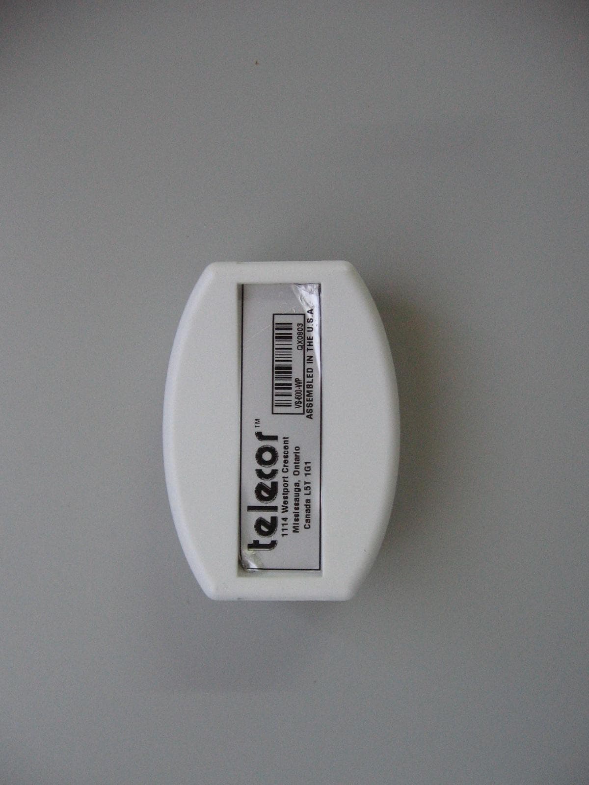
Click to zoom
Application Details
- Equipment Class
- DSR - Part 15 Remote Control/Security Device Transceiver
- Date of Grant
- Apr 28, 2010
- Application Purpose
- Original Equipment
- Date of Application
- Apr 28, 2010
- Equipment Note
- EMERGENCY RESPONSE SYSTEM (ERS) WIRELESS PENDANT
- Frequency Range
- 916.53000000 - 916.53000000
- Company
- The Sapling Company, Inc
- Country
- United States
Documents & Files
Document Text
Text extracted from the exhibit documents filed with the FCC. Open a document above to read the original.
Users Manual
Telecor Inc. 1114 Westport Cr. Mississauga, Ontario Canada, L5T 1G1 Tel: (905) 564-0801 Fax: (905) 564-0806 www.telecor.com For the VS-600 Resident Unit November 2009 Revision 0.1 (PRELIMINARY) VS-600 Resident Unit Manual LIMITED WARRANTY Telecor Inc. warrants all products bearing the Telecor name to be free from defects of material and workmanship under normal use and service for a period of one year from date of delivery. Telecor will repair or replace (at our option), free of charge, any unit that is found to be defective and returned to us under warranty. Telecor warrants all other products made by others, and distributed by us, to be covered by the manufacturers' warranty period. This warranty shall not apply to any Telecor products that have been subject to misuse, neglect, accident, modification, water, fire, lightning, paint, or used in violation of instructions furnished, repaired or altered outside of the factory. This warranty does not cover batteries, bulbs, fuses or damage caused by batteries used in connection with the product. Telecor reserves the right to make the final decision on whether there is a defect in materials or workmanship, and whether or not the product returned is within the warranty period. This warranty covers bench repairs only. Telecor will not be responsible for any costs incurred involving on-site service calls. Repair or replacement by others, fire, transportation, labour charges, indemnity, etc., are not covered by this warranty and no responsibility for same will be assumed by us. Our liability does not extend to consequential damage. AUTHORIZED REPAIR STATION: All participating Distributors and Dealers are authorized to accept Telecor products for return to us for repair or replacement, or customers may return goods to us directly, providing that return authorization has been obtained. U.S. customers are required to ship any returns or repairs to: Telecor Inc. 2434 Jerauld Avenue * U.S. customers must not Niagara Falls, New York return products to Canada USA, 14305 Canadian and all International customers are required to ship any returns or repairs to: Telecor Inc. 1114 Westport Crescent Mississauga, Ontario Canada, L5T 1G1 For details on Telecor’s Return Policy, see our Published Merchandise Return Policy. E:\VS-Care\VS-600 Manual.doc/AD © Copyright 2009 by Telecor Incorporated. All rights reserved. No part of this publication may be reproduced in any form, or by any means, without the prior written permission of Telecor Incorporated. Telecor Inc. makes no representation of warranties with respect to this manual. Further, Telecor reserves the right to make changes in the specifications o f the products described in this manual at any time without notice, and without obligation of Telecor to notify any persons of such revisions or changes. Windows XP and Windows Vista are Registered Trademarks of Microsoft in the United States and other countries. www.telecor.com FCC Notice PRODUCT NAME: VS-600 Resident Unit (VS-600) FCC Registration Number: R73ERS001 PRODUCT NAME: VS-600 Wireless Pendant (VS-600-WP) FCC Registration Number: R73ERS002 PRODUCT NAME: VS-600 Wireless Pull Cord (VS-600-WC) FCC Registration Number: R73ERS003 FCC RULES: THIS PRODUCT HAS BEEN TESTED TO COMPLY WITH FCC PART 15, SUBPART B, CLASS B – UNINTENTIONAL RADIATORS OPERATING ENVIRONMENT: FOR USE IN RESIDENTIAL AREAS FCC Compliance Statement: This device complies with Part 15 of the FCC Rules. Operation is subject to the following two conditions: (1) this device may not cause harmful interference and (2) this device must accept any interference received, including interference that may cause undesired operation. FCC Notice: This equipment has been tested and found to comply with the limits for a Class B digital device, pursuant to Part 15 of the FCC Rules. These limits are designed to provide reasonable protection against harmful interference when the equipment is operated in a residential environment. This equipment generates, uses, and can radiate radio frequency energy and, if not installed and used in accordance with the instruction manual, may cause harmful interference to radio communications. FCC Warning: Warning: The user is cautioned that changes or modifications to the unit, not expressly approved by the manufacturer, could void the user’s FCC or other authority to operate the equipment. The Party Responsible for Product Compliance: Telecor Inc. 1114 Westport Crescent Mississauga, Ontario Canada, L5T 1G1 TABLE OF CONTENTS A. Introduction...........................................................................................................A-1 A.1 VS-600 Resident Unit Overview ........................................................................A-1 A.2 Overview of Peripheral Devices.........................................................................A-2 B. VS-600 Programming ...........................................................................................B-1 B.1 Resident Unit Diagnostic Procedure..................................................................B-1 B.2 Configuring the Resident Unit for Programming ................................................B-2 B.3 Using Resident Unit Configuration Software .....................................................B-2 B.3.1 Options Tab ............................................................................................B-3 B.3.1.1 Numbers Tab ......................................................................................B-3 B.3.1.2 Supervision Numbers Tab...................................................................B-4 B.3.1.3 Misc. Tab.............................................................................................B-5 B.3.2 Saving Programming Information to a File..............................................B-5 B.3.3 Prog./Config. Tab....................................................................................B-6 B.3.4 Wireless Tool Tab ...............................…
Text truncated - open the document above for the full version.
Cover Letter(s)
The Sapling Company, Inc. 1633 Republic Road Huntingdon Valley, PA. 19006 P: 215.322.6063 F: 215.322.8498 W: www.sapling-inc.com December 15, 2009 Letter of Individual Authorization to sign Form 731 To: Timco Engineering, Inc. To whom it may concern: We hereby authorize Shaike Raz of I.T.L (Product Testing) Ltd (ITL) as an authorized individual to sign for the form 731 in the favor of the following application. IC ID: R73ERS002 Thank you, Ilan Shemesh President
Cover Letter(s)
The Sapling Company, Inc. 1633 Republic Road Huntingdon Valley, PA. 19006 P: 215.322.6063 F: 215.322.8498 W: www.sapling-inc.com December 15, 2009 To: Timco Engineering, Inc. To whom it may concern: FCC ID: R73ERS002 Pursuant to section 0.457 and 0.459 of the Commission’s Rules, we hereby request confidential treatment of information accompanying this application as outlined below: CONF APPENDIX ERS002 Schem.pdf (Schematics) CONF APPENDIX ERS002 PartsLst.pdf (BOM, or parts list) CONF APPENDIX ERS002 BlkDia.pdf (Block diagram) The above materials contain trade secrets and proprietary information not customarily released to the public. The public disclosure of these materials may be harmful to the applicant and provide unjustified benefits to its competitors. The applicant understands that pursuant to Section 0.457 of the Rules, disclosure of this application and all accompanying documentation will not be made before the date of the Grant for the application. Thank you, Ilan Shemesh President
Cover Letter(s)
The Sapling Company, Inc. 1633 Republic Road Huntingdon Valley, PA. 19006 P: 215.322.6063 F: 215.322.8498 W: www.sapling-inc.com Dec. 15, 2009 To: Timco Engineering, Inc. To whom it may concern: We hereby authorize I.T.L (Product Testing) Ltd (ITL) to act on our behalf regarding the FCC ID Certification Process for the following application: Models: ERS-MAIN-STAT-1, ERS-PENDANT-1, ERS-PCB2271A-1 FCC ID: R73ERS001, R73ERS002, R73ERS003 Thank you, Ilan Shemesh President
External Photos
Label Location
ID Label/Location Info
Label Location
ID Label/Location Info
SA0001 VS-600-WP Assembled in China SA0001 VS-600-WP TM TM FCC ID: R73ERS002 IC: 6116A-ERS002 Assembled in China 1114 Westport Crescent Mississauga, Ontario Canada L5T 1G1 FCC ID: R73ERS002 IC: 6116A-ERS002
Operational Description
Product Description The Wireless Pendant is worn by a VS-600 Resident user to allow him or her to move freely about a room yet have the ability to place a call. Calls are initiated by pressing a red call button on the Pendant. The Wireless Pendant works in conjunction with a ERS Resident Unit. The Resident Unit is designed for use with Sapling's ERS System to allow hands free and two-way communication between the resident and an attendant (the Wireless Pendant). The Unit includes a Call Button to initiate calls to a designated administrative staff location, a Call Cancel Button, a Volume Control, and Menu and Activity Information Buttons. A built-in call cord jack provides the ability to plug in a traditional call cord, allowing the resident to remotely initiate a call from the bedside.
Test Report
Test Report E92891.00 The Sapling Company, Inc. Page 1 of 44 FCC ACC M Ver 1.1 05Mayl 2000 DATE: 28 February 2010 I.T.L. (PRODUCT TESTING) LTD. FCC Radio Test Report for The Sapling Company, Inc. Equipment under test: ERS Pendant ES-600-WP Written by: _____________________________ E. Ever, Documentation Approved by: _____________________________ E. Ever, Test Engineer Approved by: _____________________________ I. Raz, EMC Laboratory Manager This report must not be reproduced, except in full, without the written permission of I.T.L. (Product Testing) Ltd. This report relates only to items tested. Test Report E92891.00 The Sapling Company, Inc. Page 2 of 44 FCC ACC M Ver 1.1 05Mayl 2000 Measurement/Technical Report for The Sapling Company, Inc. ERS Pendant ES-600-WP FCC ID: R73ERS002 IC ID: 6116A-ERS002 28 February 2010 This report concerns: Original Grant: x Class I change: Class II change: Equipment type: Part 15 Security/Remote Control Transceiver 47CFR15 Section 15.231 (a-d) Measurement procedure used is ANSI C63.4-2003. Application for Certification Applicant for this device: prepared by: (different from "prepared by") Ishaishou Raz Ilan Shemesh ITL (Product Testing) Ltd. The Sapling Company Kfar Bin Nun 451 Veit Road D.N. Shimshon 99780 Huntington Valley, PA 19006 Israel U.S.A. e-mail [email protected] Tel: +1-215-322-6063 Fax: +1-215-322-8498 e-mail: [email protected] Test Report E92891.00 The Sapling Company, Inc. Page 3 of 44 FCC ACC M Ver 1.1 05Mayl 2000 TABLE OF CONTENTS 1. GENERAL INFORMATION ------------------------------------------------------------------------------- 5 1.1 Administrative Information ................................................................................. 5 1.2 List of Accreditations ......................................................................................... 6 1.3 Product Description ........................................................................................... 7 1.4 Test Methodology .............................................................................................. 7 1.5 Test Facility ....................................................................................................... 7 1.6 Measurement Uncertainty ................................................................................. 7 2. SYSTEM TEST CONFIGURATION --------------------------------------------------------------------- 8 2.1 Justification ........................................................................................................ 8 2.2 EUT Exercise Software ..................................................................................... 8 2.3 Special Accessories .......................................................................................... 8 2.4 Equipment Modifications ................................................................................... 8 2.5 Configuration of Tested System ........................................................................ 9 3. TEST SET-UP PHOTOS ---------------------------------------------------------------------------------- 10 4. AVERAGE FACTOR CALCULATION ----------------------------------------------------------------- 11 4.1 Test Instrumentation Used .............................................................................. 13 5. PERIODIC OPERATION ---------------------------------------------------------------------------------- 14 5.1 Specification .................................................................................................... 14 5.2 Requirements .................................................................................................. 14 5.3 Results ............................................................................................................. 14 6. FIELD STRENGTH OF FUNDAMENTAL ------------------------------------------------------------ 17 6.1 Test Specification ............................................................................................ 17 6.2 Test Procedure ................................................................................................ 17 6.3 Measured Data ................................................................................................ 17 6.4 Test Instrumentation Used, Field Strength of Fundamental ............................ 21 7. RADIATED EMISSION, 9 KHZ – 30 MHZ ------------------------------------------------------------ 22 7.1 Test Specification ............................................................................................ 22 7.2 Test Procedure ................................................................................................ 22 7.3 Measured Data ................................................................................................ 22 7.4 Test Instrumentation Used, Radiated Measurements ..................................... 23 7.5 Field Strength Calculation ............................................................................... 24 8. SPURIOUS RADIATED EMISSION-------------------------------------------------------------------- 25 8.1 Test Specification ............................................................................................ 25 8.2 Test Procedure ................................................................................................ 25 8.3 Test Data ......................................................................................................... 26 8.4 Test Instrumentation Used .............................................................................. 27 9. BANDWIDTH ------------------------------------------------------------------------------------------------ 28 9.1 Test procedure ................................................................................................ 28 9.2 Results table .................................................................................................... 30 9.3 Test Equipment Used. ..............................................…
Text truncated - open the document above for the full version.
Contact Information
Applicant
Evgeny Raskin
Test Firm
Israel Testing LaboratoriesIIan Cohen
Technical Specifications
| # | Rule Parts | Frequency Range | Power Output |
|---|---|---|---|
| 1 | 15.231 | 916.53 MHz - 916.53 MHz | - |
Other Applications from The Sapling Company, Inc

R73LPA-24G-1
Nov 17, 20132.4 GHz FHSS TRANSCEIVER
Equipment Class
DSS - Part 15 Spread Spectrum Transmitter
R73HPB-24G-1
Aug 25, 20132.4GHz FHSS TRANSCEIVER
Equipment Class
DSS - Part 15 Spread Spectrum Transmitter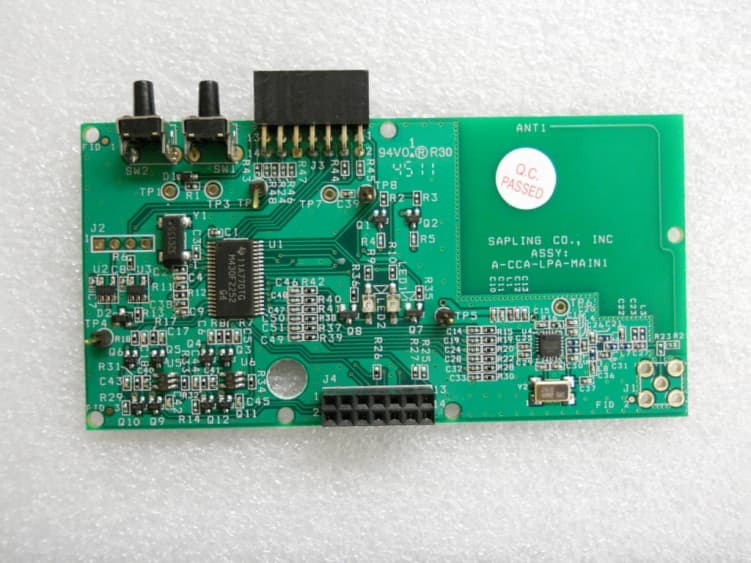
R73LPA1
Jun 19, 2012914 TO 928 MHz FREQUENCY HOPPING TRANSCEIVER MODULE
Equipment Class
DSS - Part 15 Spread Spectrum Transmitter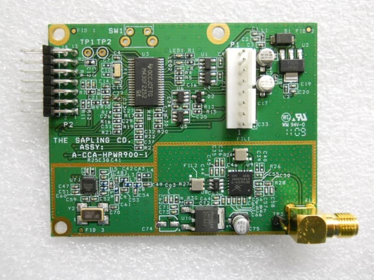
R73HPB1
May 20, 2012914 TO 928 MHz FREQUENCY HOPPING TRANSCEIVER MODULE
Equipment Class
DSS - Part 15 Spread Spectrum Transmitter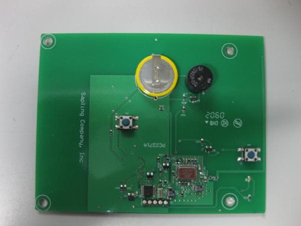
R73ERS003
Jul 04, 2010EMERGENCY RESPONSE SYSTEM (ERS) BATH STATION
Equipment Class
DXX - Part 15 Low Power Communication Device Transmitter