R73LPA1914 TO 928 MHz FREQUENCY HOPPING TRANSCEIVER MODULE
The Sapling Company, Inc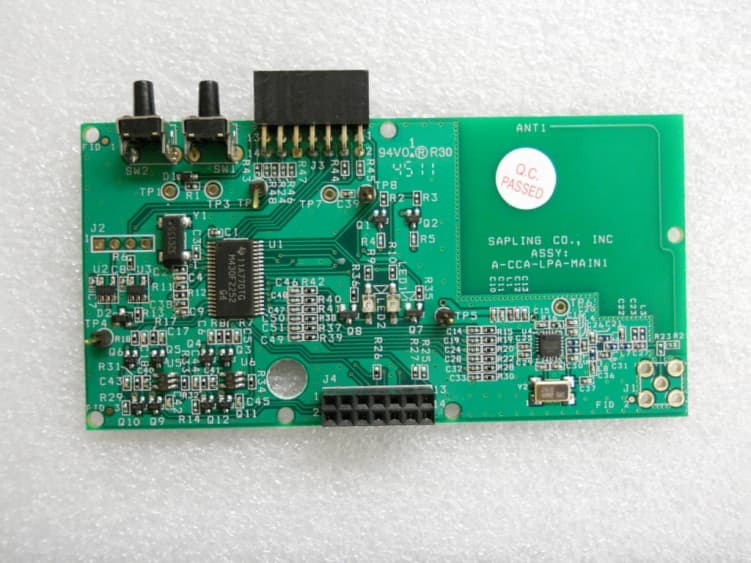
Click to zoom
Application Details
- Equipment Class
- DSS - Part 15 Spread Spectrum Transmitter
- Date of Grant
- Jun 19, 2012
- Application Purpose
- Original Equipment
- Date of Application
- Jun 19, 2012
- Equipment Note
- 914 TO 928 MHz FREQUENCY HOPPING TRANSCEIVER MODULE
- Frequency Range
- 914.00000000 - 928.00000000
- Company
- The Sapling Company, Inc
- Country
- United States
Documents & Files
Document Text
Text extracted from the exhibit documents filed with the FCC. Open a document above to read the original.
Users Manual
SAL-2 Series Wireless Clock The Sapling Company, Inc. 1633 Republic Road Huntingdon Valley, PA 19006 215.322.6063 P. 215.322.8498 F. www.sapling-inc.com Installation Manual V4 The Sapling Company, Inc. 1633 Republic Road Huntingdon Valley, PA 19006 215.322.6063 P. 215.322.8498 F. www.sapling-inc.com 2 Table of Contents SAL-2 Series Wireless Clock Table of Contents—2 Wall Mount Installation —3 Wall Mount Installation - Square Clock (wired applications)—4 Wall Mount Installation - Square Clock (wired applications)—5 Wall Mount Installation Square Clock (wireless, battery operated applications)—6 Wall Mount Installation Square Clock (wireless, battery operated applications)—7 Metal Double Mount Installation —8 Plastic Double Mount Installation —9 Plastic Double Mount Installation—10 Plastic Double Mount Installation—11 Square Double Mount Installation —12 Square Double Mount Installation —13 Square Double Mount Installation —14 Wiring Information —15 Operational Instructions—16 Installation Option #1—17 Installation Option #2—17 Installation Option #2 Continued—18 Installation Option #3—19 Installation Option #4—19 Frequently Asked Questions—20 Troubleshooting—21 Overview - Diagnostic —22 Diagnostic #1—22 Diagnostic #2—23 Diagnostic #3—23 Diagnostic #4—24 FCC Wants You to Know—25 *manuals may change without prior notice The Sapling Company, Inc. 1633 Republic Road Huntingdon Valley, PA 19006 215.322.6063 P. 215.322.8498 F. www.sapling-inc.com 3 1. Connect the wiring as shown on the wiring diagram (110V or 24V ONLY). 2. Mount both plastic anchors in the wall. 3. Insert the sheet metal screws (#10) through the mounting bracket into the plastic anchors. 4. Plug the connector into the movement (110V or 24V ONLY). 5. Hang the clock on the mounting bracket. 6. Put the screw (4mm) through the hole on the top of the clock into the hole at the top of the mounting bracket. Wall Mount Installation 12” Clock16” Clock 24 Volt/110 volt options shown in diagrams The Sapling Company, Inc. 1633 Republic Road Huntingdon Valley, PA 19006 215.322.6063 P. 215.322.8498 F. www.sapling-inc.com 4 Wall Mount Installation - Square Clock (wired applications) q w w w e e r The Sapling Company, Inc. 1633 Republic Road Huntingdon Valley, PA 19006 215.322.6063 P. 215.322.8498 F. www.sapling-inc.com 5 Wall Mount Installation - Square Clock (wired applications) q Separate the front of the clock from the back case - Locate the four (4) tabs (two (2) on the left side and two (2) on the right side of the clock) and disengage those tabs by pressing down on them with a flathead screw driver no further than 1/4 inch. This will allow the front of the clock to separate from the back case section of the clock. The back case is the portion that will be mounted to the wall first. Make sure that both the clock and the back case are facing in the upright position before moving on to the next steps. w Mount the back case and mounting cap to the switch box - Make sure that the mounting cap is slid into place on the back case. *Note: the mounting cap should slide on to the top side of the clock. Pull all necessary wires from the switch box through the hole in the back case and mounting cap (9”- use the top hole, 12” or 16” - use either the top or second to the top hole). Line up the two holes in the back case of the clock and the mounting cap with the two holes that line up with the top and bottom of the switch box. Note: the back case of the clock and the mounting cap are provided with holes that line up with the holes on a double switch box as well - these holes are located on the four outter most holes of the back case and the mounting cap. Using the 6-32x1" screws included in the supplied kit, screw the back case and mounting cap to the switch box. e Plug and secure wiring - Take the wiring that should now be routed through the switch box and through the hole in the back case and mounting cap and secure it to the back case by slipping it under the clamps or tabs located within the back case. The user will choose the clamps and tabs used based on the amount of excess wiring present inside the back case. Take the front of the clock that was separated from the back case in step 1 and plug the end of the wiring into the appropriate jack on the movement. r Attach the front of the clock to the back case - With the wiring now secured and properly plugged into the movement, take the front of the clock and snap it back together with the back case. Press the front of the clock into the back case, making sure the tabs that were disengaged in step one are properly snapped back together. Note: when pressing the front of the clock onto the back case, DO NOT press on the center of the clock. Rather, push on the outer edges of the frame of the clock as to not damage the contents of the clock. The Sapling Company, Inc. 1633 Republic Road Huntingdon Valley, PA 19006 215.322.6063 P. 215.322.8498 F. www.sapling-inc.com 6 Wall Mount Installation Square Clock (wireless, battery operated applications) q w r t e The Sapling Company, Inc. 1633 Republic Road Huntingdon Valley, PA 19006 215.322.6063 P. 215.322.8498 F. www.sapling-inc.com 7 q Separate the front of the clock from the back case - Locate the four (4) tabs (two (2) on the left side and two (2) on the right side of the clock) and disengage those tabs by pressing down on them with a flathead screw driver no further than 1/4 inch. This will allow the front of the clock to separate from the back case section of the clock. The back case is the portion that will be mounted to the wall first. Make sure that both the clock and the back case are facing in the upright position before moving on to the next steps. w Screw the mounting cap to the switch box or wall - Line up the upper keyhole style mounting point on the mounting cap with the upper hole on the switch box and screw it in using one (1) of the 6-32/1” screws supplied in the kit. Note: with this mounting option, the installer cannot mount to a double …
Text truncated - open the document above for the full version.
Users Manual
User Manual May 2012 914-928 MHz Frequency Hopping Transceiver Module Model: PCB-LPA-MAIN1 FCC ID: R73LPA1 Introduction: This module is only authorized to be installed in fixed mount installation and may not be installed in a mobile or portable device. The LPA-MAIN1 RF module is to be used in Sapling Analog Clocks such as the SAL Series Clocks and equivalent models. The module is only to be connected to other Sapling products. Specifications: The maximum output power will be 10 dBm. The transmit cycle is a sequence of 57 data strings on 51 different frequencies, each transmitted for 10 msec. Every transmit cycle is 570 msec in duration (57 x 10ms). The frequency hopping pattern is proprietary to Sapling and covers the range from 914.688 to 927.488 MHz. Connections: The module should only be connected to and installed in other Sapling products. The picture shows the LPA-MAIN1 RF module and connectors. LPA-MAIN1 LPA-MAIN1 J4 J3 LPA-MAIN1 RF Connectors: J3 PROGRAMMING CONNECTOR PIN 1 TDO/TDI PIN 2 3.3 VOLTS PIN 3 TDI PIN 4 3.3 VOLTS PIN 5 S2 DRV (TMS) PIN 6 1.8 VOLTS PIN 7 TCLK PIN 8 TEST PIN 9 GROUND PIN 10 GROUND PIN 11 RST PIN 12 TXD PIN 13 SHIELD PIN 14 RXD * PIN 1 IS SQUARE PAD J4 GEARBOX CONNECTOR PIN 1 MOT SEC 1 1.8 VOLTS PIN 2 MOT SEC 2 PIN 3 MOT MIN 1 1.8 VOLTS PIN 4 MOT MIN 2 PIN 5 GRBX SEL A PIN 6 GRBX SEL B PIN 7 PWR DET PIN 8 S1 PIN 9 GROUND PIN 10 S2 PIN 11 3.3 VOLTS PIN 12 GRBX DET PIN 13 1.8 VOLTS PIN 14 GROUND * PIN 1 IS SQUARE PAD Operation: The module will transmit the time for 570 ms, as specified. Line powered version will transmit once a minute. Battery powered version will transmit every 2 hours. FCC Statement: This device complies with part 15 of the FCC Rules. Operation is subject to the following two conditions: (1) This device may not cause harmful interference, and (2) this device must accept any interference received, including interference that may cause undesired operation. NOTE: THE MANUFACTURER IS NOT RESPONSIBLE FOR ANY RADIO OR TV INTERFERENCE CAUSED BY UNAUTHORIZED MODIFICATIONS TO THIS EQUIPMENT. SUCH MODIFICATIONS COULD VOID THE USER’S AUTHORITY TO OPERATE THE EQUIPMENT.
Block Diagram
55 44 33 22 11 D D C C B B A A TitleSize Document Number Rev Date: Sheet of <Doc> 1.0 <Title> A 11 Tuesday, January 10, 2012 TitleSize Document Number Rev Date: Sheet of <Doc> 1.0 <Title> A 11 Tuesday, January 10, 2012 TitleSize Document Number Rev Date: Sheet of <Doc> 1.0 <Title> A 11 Tuesday, January 10, 2012 900 MHZ LOW-POWER-ANALOG BLOCK DIAGRAM MOSIMISOCLKENABLE PROCESSOR CC1101TEXAS INSTRUMENTS RF TRANSCEIVER IC BALUN SPI SERIAL COMMUNICATIONS QUARTER-WAVEMONOPOLE @ 915 MHz +10 DBm OUTPUT @ 50 OHM ANT1 PCB TRACK ANTENNA ANT1 PCB TRACK ANTENNA Y1 32.768KHZ Y1 32.768KHZ Y226.000 MHzY226.000 MHz 43 12
External Photos
The Sapling Company, Inc. FCC ID: R73LPA1 Retlif Testing Laboratories Internal Photographs Top Bottom
ID Label/Location Info
Label Location
ID Label/Location Info
Label Sample
Internal Photos
The Sapling Company, Inc. FCC ID: R73LPA1 Retlif Testing Laboratories Internal Photographs Top Bottom
Operational Description
Antenna Description The Sapling Company, Inc. FCC ID: R73LPA1 The quarter wave monopole antenna is a single element antenna fed at one end, that behaves as a dipole antenna. It is formed by a conductor ¼ in length. It is fed in the lower end, which is near a conductive surface which works as a reflector. The current in the reflected image has the same direction and phase as the current in the real antenna. The quarter-wave conductor and its image together form a half-wave dipole that radiates only in the upper half of space. In this upper side of space the emitted field has the same amplitude of the field radiated by a half-wave dipole fed with the same current. Therefore, the total emitted power is one-half the emitted power of a half-wave dipole fed with the same current. As the current is the same, the radiation resistance (real part of series impedance) will be one- half of the series impedance of a half-wave dipole. As the reactive part is also divided by 2, the impedance of a quarter wave antenna is (73 + i43) / 2 = (36 + i21) ohms. Since the fields above ground are the same as for the dipole, but only half the power is applied, the gain is twice (3dB over) that for a half-wave dipole ½, that is 5.14 dBi.
Test Report
Retlif Testing Laboratories, Test Report R-1735P-2, The Sapling Company, Inc. FCC ID: R73LPA1 Page 1 of 34 Technical Information Applicant Manufacturer Name: The Sapling Company, Inc. Name: The Sapling Company, Inc. Address: 1633 Republic Road Address: 1633 Republic Road City, State, Zip: Huntington Valley, PA 19006 City, State, Zip: Huntington Valley, PA 19006 Date of Report: May 30, 2012 Test Specification: FCC Rules and Regulations Part 15, Subpart C, Para. 15.247 Test Procedure: ANSI C63.4:2003 FCC Public Notice DA 00-705, Dated: March 30, 2000 Test Sample Description TEST SAMPLE: 914 to 928 MHz Transceiver Module BRANDNAME: Sapling MODEL: LPM-900-1 FCC ID: R73LPA1 TYPE: Frequency Hopping Spread Spectrum Transceiver Module POWER REQUIREMENTS: 120 VAC, 60 Hz FREQUENCY OF OPERATION: 914 to 928 MHz T ests Performed FCC Part 15, Subpart C Test Method 15.247(a)(1) Channel Separation 15.247(a)(1) 20 dB Bandwidth 15.247(a)(1) (i) Number of Channels and Occupancy Time 15.247(b)(1) and (4) Peak Conducted Output Power 15.247(d) Field Strength of Spurious Emissions, 32.7 kHz to 10 GHz 15.207(b) Conducted Emissions, Power Leads, 150 kHz to 30 MHz Retlif Testing Laboratories, Test Report R-1735P-2, The Sapling Company, Inc. FCC ID: R73LPA1 Page 3 of 34 General Test Requirements 1. The measurement procedures of ANSI C63.4:2003 were utilized as specified in FCC Part 15, Subpart C, Section 15.31(a)(3). 2. All radiated emissions measurements were performed on an Open Area Test Site (OATS), listed with the FCC, in accordance with FCC Section 15.31(d). 3. The level of the RF power output was measured with the AC input varied from 85 to 115% of rated. The worst case results were reported in accordance with FCC Section 15.31(e). 4. All radiated emissions measurements were performed at the specified 3 meter test distance as required by FCC Section 15.31(f). 5. The EUT was rotated throughout 360 degrees for all radiated emissions measurements as specified in FCC Section 15.31(f)(5). 6. All readily accessible EUT controls were adjusted in such a manner as to maximize the level of emissions in accordance with FCC Section 15.31(g). 7. Appropriate accessories were attached to all EUT ports during the performance of radiated emissions measurements as required by FCC Section 15.31(i). 8. AC line conducted emissions were measured utilizing a 50 Ohm / 50 MicroHenry LISN as specified in FCC Section 15.31(l). 9. The EUT operated over the frequency range of 914 to 928 MHz. A total range of 14 MHz. Testing was performed with the device operating at 3 frequencies, 1 at the top, 1 in the middle and 1 at the bottom of the range of operation in accordance with FCC Section 15.31(m). 10. The frequency spectrum was investigated from the lowest frequency generated in the device up to the 10 th harmonic of the highest fundamental frequency in accordance with FCC Section 15.33(a)(1). 11. Measurements below 1000 MHz were taken utilizing a Quasi-Peak Detector. Measurements above 1 GHz were taken utilizing an Average Detector in accordance with FCC Section 15.35(a). The peak value of emissions above 1 GHz were verified to meet the 20 dB requirement of FCC Section 15.35(b). Retlif Testing Laboratories, Test Report R-1735P-2, The Sapling Company, Inc. FCC ID: R73LPA1 Page 4 of 34 Requirements and Test Results Requirement: FCC Section 15.203 Antenna Requirements An intentional radiator shall be designed to ensure that no antenna other than that furnished by the responsible party shall be used with the device. The use of a permanently attached antenna or of an antenna that uses a unique coupling to the intentional radiator shall be considered sufficient to comply with the provisions of this section. The manufacturer may design the unit so that a broken antenna can be replaced by the user, but the use of a standard antenna jack or electrical connector is prohibited. This requirement does not apply to carrier current devices or to devices operated under the provisions of §15.211, §15.213, §15.217, §15.219, or §15.221. Further, this requirement does not apply to intentional radiators that must be professionally installed, such as perimeter protection systems and some field disturbance sensors, or to other intentional radiators which, in accordance with §15.31(d), must be measured at the installation site. However, the installer shall be responsible for ensuring that the proper antenna is employed so that the limits in this part are not exceeded. Results: This module, when integrated into the final product, is distributed and professionally installed through a dealer network, therefore the module is deemed compliant with FCC Section 15.203. Requirement: FCC Section 15.207(a) - Conducted Limits For an intentional radiator that is designed to be connected to the public utility (AC) power line, the radio frequency voltage that is conducted back onto the AC power line on any frequency or frequencies within the band 150 kHz to 30 MHz shall not exceed the limits shown in Table 1, as measured using a 50 μH/50 ohms line impedance stabilization network (LISN). Compliance with the provisions of the paragraph shall be based on the measurement of the radio frequency voltage between each power line and ground at the power terminal. The lower limit applies at the boundary between the frequency ranges. Table 1 - Conducted Emission Limits Frequency of Emission (MHz) Conducted Limit (dBμV) Quasi-Peak Average 0.15 to 0.5 66 to 56* 56 to 46* 0.5 to 5 56 46 5 to 30 60 50 *Decreases due to logarithm of the frequency Results: The conducted emissions observed did not exceed the limits specified in Table 1. Retlif Testing Laboratories, Test Report R-1735P-2, The Sapling Company, Inc. FCC ID: R73LPA1 Page 5 of 34 Requirements and Test Results (con’t) FCC Section 15.209(a) Radiated Emission Limits, General Requirements Except for Class A digital devices, the field strength of radiated emissions from unintentional radiators at a distance of 3 meters shall not e…
Text truncated - open the document above for the full version.
Test Setup Photos
Retlif Testing Laboratories, Test Report R-1735P-2, The Sapling Company, Inc. FCC ID: R73LPA1 Page 1 of 7 Test Setup Photographs The Sapling Company, Inc. FCC ID: R73LPA1 Retlif Testing Laboratories, Test Report R-1735P-2, The Sapling Company, Inc. FCC ID: R73LPA1 Page 2 of 7 Test Photographs Channel Separation, 20 dB Bandwidth and Number of Channels and Occupancy Time Test Setup Retlif Testing Laboratories, Test Report R-1735P-2, The Sapling Company, Inc. FCC ID: R73LPA1 Page 3 of 7 Test Photographs Peak Conducted Output Power Test Setup Retlif Testing Laboratories, Test Report R-1735P-2, The Sapling Company, Inc. FCC ID: R73LPA1 Page 4 of 7 Test Photographs Spurious Emissions Test Setup Retlif Testing Laboratories, Test Report R-1735P-2, The Sapling Company, Inc. FCC ID: R73LPA1 Page 5 of 7 Test Photographs Field Strength of Spurious Emissions EUT Configuration, Horizontal EUT Configuration, Vertical Retlif Testing Laboratories, Test Report R-1735P-2, The Sapling Company, Inc. FCC ID: R73LPA1 Page 6 of 7 Test Photographs Field Strength of Spurious Emissions Horizontal Antenna Polarization Vertical Antenna Polarization Retlif Testing Laboratories, Test Report R-1735P-2, The Sapling Company, Inc. FCC ID: R73LPA1 Page 7 of 7 Test Photographs Conducted Emissions EUT Configuration Test Setup
Contact Information
Applicant
Evgeny Raskin
Test Firm
Retlif Testing LaboratoriesMichael Bozza
Technical Specifications
| # | Rule Parts | Frequency Range | Power Output |
|---|---|---|---|
| 1 | 15C | 914 MHz - 928 MHz | 10.00 mW |
Other Applications from The Sapling Company, Inc

R73LPA-24G-1
Nov 17, 20132.4 GHz FHSS TRANSCEIVER
Equipment Class
DSS - Part 15 Spread Spectrum Transmitter
R73HPB-24G-1
Aug 25, 20132.4GHz FHSS TRANSCEIVER
Equipment Class
DSS - Part 15 Spread Spectrum Transmitter
R73HPB1
May 20, 2012914 TO 928 MHz FREQUENCY HOPPING TRANSCEIVER MODULE
Equipment Class
DSS - Part 15 Spread Spectrum Transmitter
R73ERS003
Jul 04, 2010EMERGENCY RESPONSE SYSTEM (ERS) BATH STATION
Equipment Class
DXX - Part 15 Low Power Communication Device Transmitter
R73ERS002
Apr 28, 2010EMERGENCY RESPONSE SYSTEM (ERS) WIRELESS PENDANT
Equipment Class
DSR - Part 15 Remote Control/Security Device Transceiver