R73SAL001SAL SERIES WIRELESS CLOCK
The Sapling Company, Inc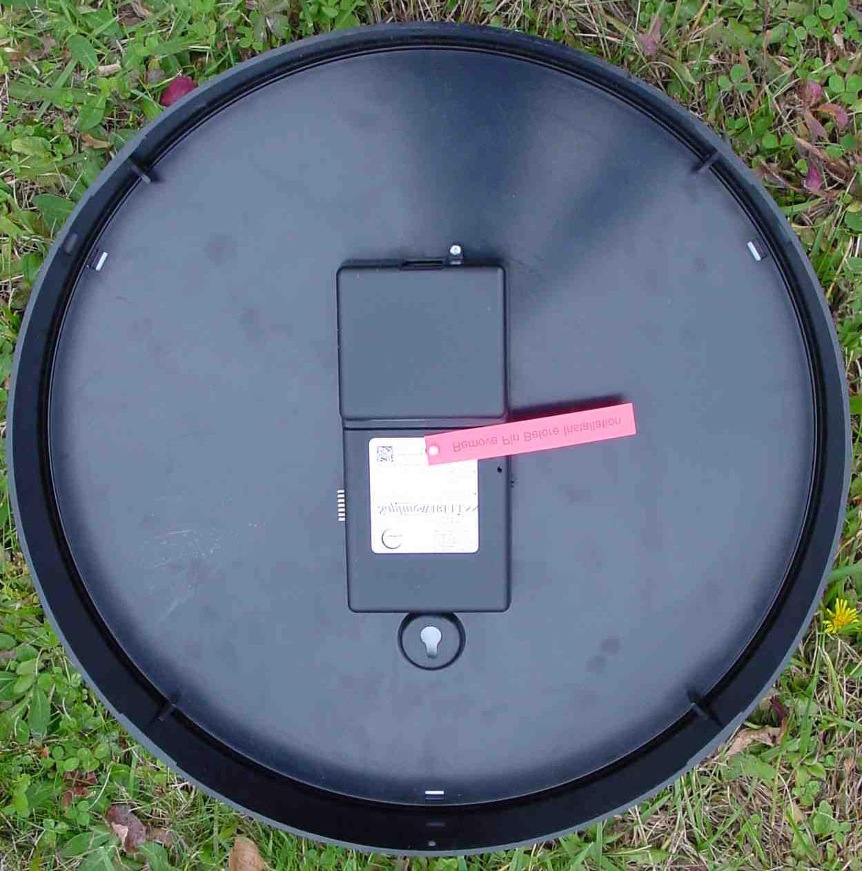
Click to zoom
Application Details
- Equipment Class
- DSS - Part 15 Spread Spectrum Transmitter
- Date of Grant
- Nov 17, 2004
- Application Purpose
- Original Equipment
- Date of Application
- Nov 17, 2004
- Equipment Note
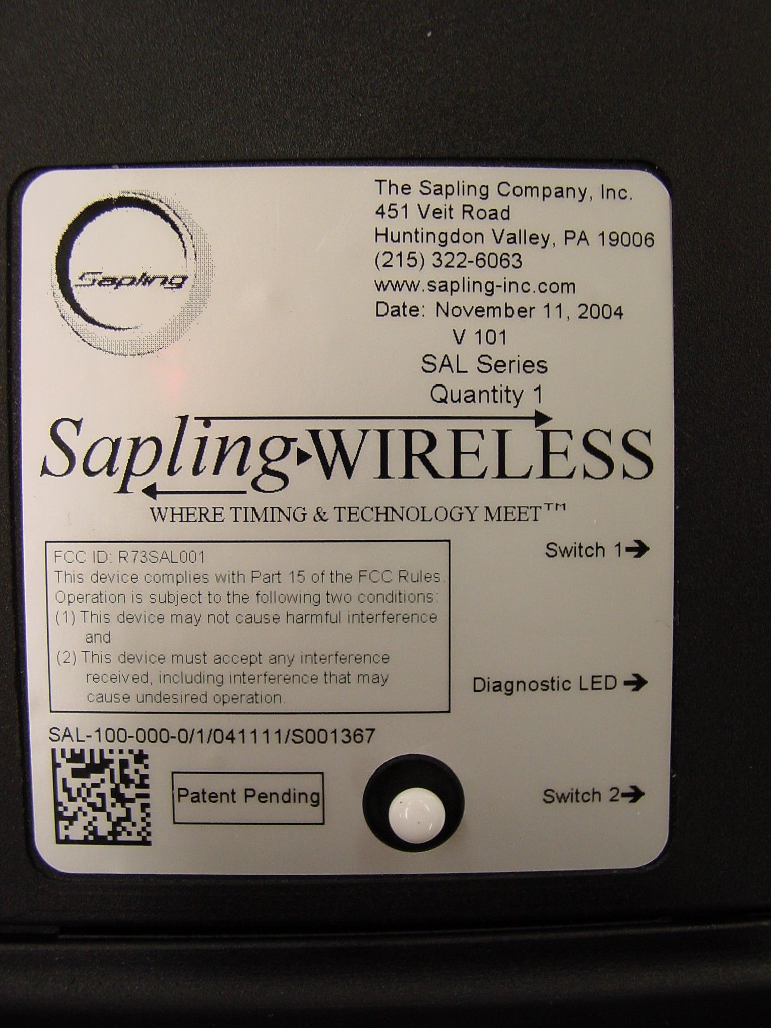
- SAL SERIES WIRELESS CLOCK
- Frequency Range
- 914.28000000 - 927.65000000
- Company
- The Sapling Company, Inc
- Country
- United States
Documents & Files
Document Text
Text extracted from the exhibit documents filed with the FCC. Open a document above to read the original.
Users Manual
INSTALLATION MANUAL FOR SAL SERIES WIRELESS CLOCKS Time base: Quartz Power input: Battery (2 “D” cell) : Part # SAL-1BS-12R-0 95 – 135 VAC / 60 Hz: Part # SAL-1BS-12R-1 7 – 28 VAC / 60 Hz: Part # SAL-1BS-12R-4 Current consumption: Battery– 5 year, 2 “D” cell** 20 mA @ 24 VAC 15 mA @110 VAC Power Output 8dbm Display: 12 hour format. Hour, minute and second hands Color: Standard Black Clock Size: 12” diameter, 2.2” depth, 16” diameter, 2.2” depth Shipping Weight: 12” - Approx. 2.5lb. 16” - Approx - 4.0 lb. Case: Smooth surface ABS case Crystal: Shatter-proof, side molded polycarbonate crystal in 12” and 16” models FCC Compliant. FCC part 15 Section 15,248 ** Provided good reception SPECIFICATIONS The Sapling Company, Inc. 451 Veit Road Huntingdon Valley, PA 19006 Phone: (215) 322-6063 Fax: (215) 322-8498 www.Sapling-Inc.com Page 1 TABLE OF CONTENTS TABLE OF CONTENTS FCC COMPLIANCE Description .........................................Page 3 MOUNTING INSTRUCTIONS nstructions for All Models......................................... Pages OVERVIEW ......................................... Pages OPERATIONAL INSTRUCTIONS ......................................... Pages FREQUENTLY ASKED QUESTIONS (FAQ’S) ......................................... Pages The FCC Wants You to Know This equipment has been tested and found to comply with the limits for a Class B digital device, pursuant to Part 15 of the FCC rules. These limits are designed to provide reasonable protection against harmful interference in a residential installation. This equipment generates, uses and can radiate radio frequency energy and, if not installed and used in accordance with the instructions, may cause harmful interference to radio communications. However, there is no guarantee that interference will not occur in a particular installation. If this equipment does cause harmful interference to radio or television reception, which can be determined by turning the equipment off and on, the user is encouraged to try to correct the interference by one or more of the following measures: a) Reorient or relocate the receiving antenna. b) Increase the separation between the equipment and receiver. c) Connect the equipment to an outlet on a circuit different from that to which the receiver is connected. d) Consult the dealer or an experienced radio/TV technician. FCC Warning Modifications not expressly approved by the manufacturer could void the user authority to operate the equipment under FCC Rules. "Instructions concerning human exposure to radio frequency electromagnetic fields. To comply with FCC Section 1.307 (b)(1) for human exposure to radio frequency electromagnetic fields, implement the following instruction: A distance of at least 20cm. between the equipment and all persons should be maintained during the operation of the equipment." The SAL Series clocks is a wireless analog clock is available in battery operated, 110V or 24V power input. The SAL Wireless clocks are also available in 12” and 16” versions, as well as single and double mount styles. It is designed to work with the STR Series Transmitter/Master Clock. The wireless system is interchangeable with Sapling’s SBL Series digital clock. The 110V and 24V wireless analog series receives and transmits time every minute, as opposed to the battery-operated version which receives and transmits time every four (4) hours. Sapling’s revolutionary SAL Series wireless clock has been designed to work in environments when cabling options are not available. The SAL clock Series works in 915-928 mHz frequency-hopping technology. The innovative 915-928 mHz frequency-hopping technology transmits data along several alternating signal frequencies. This multi-layer approach guarantees an enhanced signal even if there is interference in one of the frequencies. The unit can both receive and transmit wireless signals which allows it to be used as a repeater, boosting the data stream and sending it along the system. There is no limitation to the number of clocks in the installation. The SAL Series clocks are designed to work together, without causing any interference with each other in an automatic fashion. The more clocks in a specific area would increase the quality of the signal. The SAL Series clock is designed to work in conjunction STR Series Transmitter that is capable of working as a master clock for a new system, it can act as a signal booster to extend the range of a wireless system, or it can be used to translate an existing system into a wireless system. Sapling’s high power wireless Transmitter allows the user to create a wireless clock system from an existing hard-wired system. The transmitter incorporates multifunction software so that every transmitter can transmit and receive signals. Distances of the SAL Series Analog Clock is 656 feet (200 meters) in open space which allows for a typical 164 feet (50 meters) within a building (typical distances Distances of the STR Series Transmitter Analog Clock is 3280 feet (1000 meters) in open space which allows for a typical 492 feet (150 meters) within a building (typical distances will vary depending on the type of the building, wall construction, number of walls and etc.)
Block Diagram
batteries or power supply microcontrollertransceiver 16.384Mhz gearbox clock hands 32.768Khz tx antenna rx antenna selector 4Mhz 2 push buttons
Cover Letter(s)
The Sapling Company, Inc. 451 Veit Road Huntingdon Valley, PA. 19006 P: 215.322.6063 F: 215.322.8498 W: www.sapling-inc.com Attn: Reviewing Engineer Federal Communications Commission 7435 Oakland Mills Road Columbia, MD 21046 November 11, 2004 RE: CONFIDENTIALITY REQUEST FOR THE SAL SERIES WIRELESS CLOCK SYSTEM. FCC ID#: R73SAL001 To Whom It May Concern: This letter serves as an official request for confidentiality under FCC Rule Section 0.459. We have requested that the schematic diagrams required to be submitted with this application be withheld from public review. We require confidentiality due to the patent(s) that we are currently obtaining. Please contact me if there is any information you may need. Sincerely, Ilan Shemesh President
External Photos
Figure 1 Front View SAL-1BS-12R-1 Figure 2 Rear View SAL-1BS-12R-1 Figure 3 Front View SAL-1BS-16R-1 Figure 4 Rear View SAL-1BS-16R-1 Figure 5 Front View SAL-1BS-12R-0 Figure 6 Rear View SAL-1BS-12R-0 Figure 7 Front View SAL-1BS-16R-0 Figure 8 Rear View SAL-1BS-16R-0
Internal Photos
Internal Photographs of Tested E.U.T. Figure 1 PCB and AC Power Supply in Case Figure 2 PCB in Case Figure 3 AC Power Supply in Case Figure 4 PCB Side 1 Figure 5 PCB Side 2 Figure 6 AC Power Supply Side 1 Figure 7 AC Power Supply Side 2 Figure 8 AC Connector
Operational Description
The wireless clock is based on micro-controller. The micro-controller controls the movement of the hands of the clock through a gear box. The gearbox outputs a signal of the hands position to the micro-controller. The micro-controller uses this signal to make sure it displays the correct time. The clock receives the correct time through RF communication. Any time it receives time, it also transmits the correct time to other clocks. For that purpose the clock includes a transceiver. The micro-controller uses this transceiver to receive and transmit messages in frequency hopping technology in the 915-928 MHz frequency range. The transceiver is connected to 2 antennas, one for transmit and one for receive. These are internal antennas printed on the print. The clock transmits the same time message in 51 different frequencies. It stays 10 mili-seconds in every channel before it hops to the next channel but it transmits only 6.64 mili-seconds during this time. After 51 different frequencies it transmits another 9 messages starting at the first frequency. In worst case the clock transmits the time message every 1 minute. The all transmission endure 600 mili-seconds. Which mean, in worst case it stays 13.3 mili-seconds at the same frequency during 1 minute. The clock is available in battery operated,110V or 24V power input. The 110V and 24V wireless analog series receives and transmits time every minute, as opposed to the battery-operated version which receives and transmits time every four (4) hours. The clock is designed to consume very little energy. For that the microcontroller controls the frequency of its operation by a selector which gives the option to select 32.768 khz (low frequency) or 4 Mhz (high frequency). The clock includes 2 push buttons. One of them allows the user to drive the clock into receive or transmit mode (since most of the time the clock is not open for communication). The other one allows the user to drive the clock into debug mode.
Test Report
Cert. No. 1152.01 Electrical (EMC) Test Report E55521.00 The Sapling Company Inc.Page 1 of 91 FCC ACC M Ver 1.1 05Mayl 2000 DATE: 12 October 2004 I.T.L. (PRODUCT TESTING) LTD. FCC EMC/Radio Test for The Sapling Company Inc. Equipment under test: RF Clock (Transmitter Section) SAL-1BS-12R-1 * * See customer’s declaration on page 6 and Appendices B; C. Written by:_____________________________ D. Shidlowsky, Documentation Approved by: _____________________________ E. Pitt, Test Engineer Approved by:_____________________________ I. Raz, EMC Laboratory Manager This report must not be reproduced, except in full, without the written permission of I.T.L. (Product Testing) Ltd. This report relates only to items tested. Cert. No. 1152.01 Electrical (EMC) Test Report E55521.00 The Sapling Company Inc.Page 2 of 91 FCC ACC M Ver 1.1 05Mayl 2000 Measurement/Technical Report for The Sapling Company Inc. RF Clock (For Transmitter Section) SAL-1BS-12R-1 FCC ID:R73 SAL001 12 October 2004 This report concerns:Original Grant x Class II change Class B verification Class A verification Class I change Equipment type: Radio Telemetry Transmitter Request Issue of Grant: x Immediately upon completion of review Limits used: CISPR 22 Part 15 x Measurement procedure used is ANSI C63.4-2001. Application for Certification Applicant for this device: prepared by:(different from "prepared by") Ishaishou RazIlan Shemesh ITL (Product Testing) Ltd.The Sapling Company Kfar Bin Nun451 Veit Road D.N. Shimshon 99780Huntington Valley, PA 19006 IsraelU.S.A. e-mail [email protected]:+1-215-322-6063 Fax:+1-215-322-8498 e-mail: [email protected] Test Report E55521.00 The Sapling Company Inc.Page 3 of 91 FCC ACC M Ver 1.1 05Mayl 2000 TABLE OF CONTENTS 1.GENERAL INFORMATION ------------------------------------------------------------------------------- 5 1.1Administrative Information .................................................................................5 1.2List of Accreditations .........................................................................................7 1.3Product Description ...........................................................................................8 1.4Test Methodology ..............................................................................................8 1.5Test Facility .......................................................................................................9 1.6Measurement Uncertainty .................................................................................9 2.PRODUCT LABELING------------------------------------------------------------------------------------10 3.SYSTEM TEST CONFIGURATION--------------------------------------------------------------------11 3.1Justification......................................................................................................11 3.2EUT Exercise Software ...................................................................................11 3.3Special Accessories ........................................................................................11 3.4Equipment Modifications .................................................................................11 3.5Configuration of Tested System ......................................................................12 4.BLOCK DIAGRAM -----------------------------------------------------------------------------------------12 4.1Schematic Block/Connection Diagram ............................................................12 4.2Theory of Operation.........................................................................................13 5.CUSTOMER’S DECLARATION ------------------------------------------------------------------------14 6.CONDUCTED EMISSION DATA -----------------------------------------------------------------------15 6.1Test Specification ............................................................................................15 6.2Test Procedure ................................................................................................15 6.3Measured Data ................................................................................................16 6.4Test Instrumentation Used, Conducted Measurement....................................19 7.SPURIOUS RADIATED EMISSION, BELOW 1 GHZ ---------------------------------------------20 7.1Test Specification ............................................................................................20 7.2Test Procedure ................................................................................................20 7.3Measured Data ................................................................................................20 7.4Test Instrumentation Used, Radiated Measurements .....................................21 7.5Field Strength Calculation ...............................................................................22 8.SPURIOUS RADIATED EMISSION ABOVE 1 GHZ-----------------------------------------------23 8.1Radiated Emission Above 1 GHz ....................................................................23 8.2Test Data .........................................................................................................23 8.3Test Instrumentation Used, Radiated Measurements Above 1 GHz...............36 9.NUMBER OF HOPPING FREQUENCIES------------------------------------------------------------37 9.1Test procedure ................................................................................................37 9.2Results table....................................................................................................40 9.3Test Equipment Used. .....................................................................................40 10.CHANNEL FREQUENCY SEPARATION ------------------------------------------------------------41 10.1 Test procedure ................................................................................................41 10.2 Results table....................…
Text truncated - open the document above for the full version.
Test Setup Photos
Test set-up Photos Figure 1. Conducted Emission Test. Figure 2. Radiated Emission Test.
Contact Information
Applicant
Evgeny Raskin
Test Firm
Israel Testing LaboratoriesIIan Cohen
Technical Specifications
| # | Rule Parts | Frequency Range | Power Output |
|---|---|---|---|
| 1 | 15C | 914.28 MHz - 927.65 MHz | 5.40 mW |
Other Applications from The Sapling Company, Inc

R73LPA-24G-1
Nov 17, 20132.4 GHz FHSS TRANSCEIVER
Equipment Class
DSS - Part 15 Spread Spectrum Transmitter
R73HPB-24G-1
Aug 25, 20132.4GHz FHSS TRANSCEIVER
Equipment Class
DSS - Part 15 Spread Spectrum Transmitter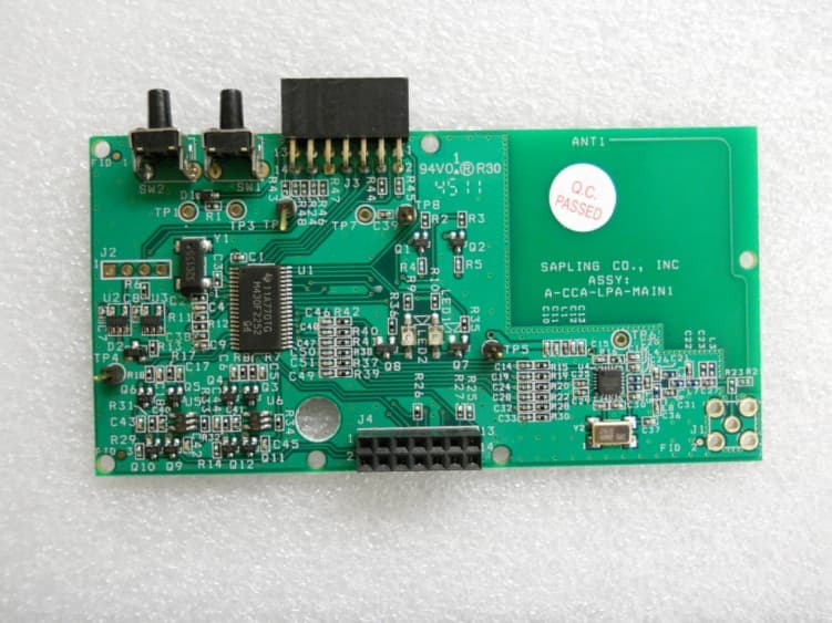
R73LPA1
Jun 19, 2012914 TO 928 MHz FREQUENCY HOPPING TRANSCEIVER MODULE
Equipment Class
DSS - Part 15 Spread Spectrum Transmitter
R73HPB1
May 20, 2012914 TO 928 MHz FREQUENCY HOPPING TRANSCEIVER MODULE
Equipment Class
DSS - Part 15 Spread Spectrum Transmitter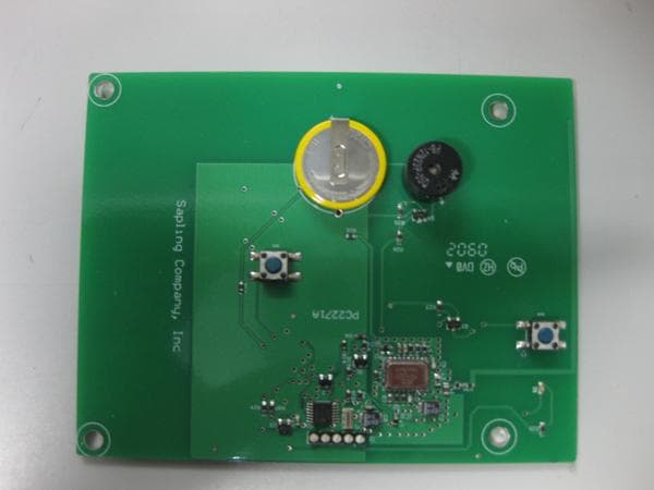
R73ERS003
Jul 04, 2010EMERGENCY RESPONSE SYSTEM (ERS) BATH STATION
Equipment Class
DXX - Part 15 Low Power Communication Device Transmitter