R73STR001STR 2000 / STR 1000
The Sapling Company, Inc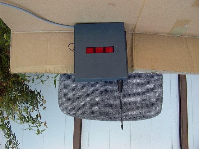
Click to zoom
Application Details
- Equipment Class
- DSS - Part 15 Spread Spectrum Transmitter
- Date of Grant
- Nov 22, 2005
- Application Purpose
- Original Equipment
- Date of Application
- Nov 22, 2005
- Equipment Note
- STR 2000 / STR 1000
- Frequency Range
- 914.81000000 - 927.61000000
- Company
- The Sapling Company, Inc
- Country
- United States
Documents & Files
Document Text
Text extracted from the exhibit documents filed with the FCC. Open a document above to read the original.
Users Manual
STR 2000 Series Transceiver Installation Manual Sapling, Inc. 1633 Republic Road Huntingdon Valley, PA 19006 Phone: (215) 322-6063 Fax: (215) 322-8498 www.Sapling-Inc.com MOUNTING Mounting Diagram.................................................................................... Page 2 WIRING INFORMATION Wiring Information................................................................................... Page 3 INTERFACING 59 Minute Correction................................................................................ Page 4 58 Minute Correction................................................................................. Page 4 National Time and Rauland......................................................................... Page 5 Rauland Digital........................................................................................ Page 5 Dukane................................................................................................. Page 6 Once A Day Pulse.................................................................................... Page 6 RS232 and TCP/IP.................................................................................... Page 7 PROGRAMMABLE RELAY Programmable Relay Wiring......................................................................... Page 8 FREQUENTLY ASKED QUESTIONS STR 2000 Frequently Asked Questions............................................................ Page 9 TROUBLESHOOTING STR 2000 Troubleshooting.......................................................................... Page 10 Page 1 Table of Contents FOR SYSTEM WIRING DIAGRAMS, PLEASE REFER TO SYSTEM INFORMATION STR 2000 Series Transceiver Installation Manual Sapling, Inc. 1633 Republic Road Huntingdon Valley, PA 19006 Phone: (215) 322-6063 Fax: (215) 322-8498 www.Sapling-Inc.com 1. Find a location that will allow the Transceiver to transmit the signal in open space. (hallway recommended) 2. Run the wiring through the knockouts and connect according to the wir- ing information. 3. Tighten all four (4) screws (6-32) on the front panel. 4. Line up the Transceiver in the desired mounting location and mark the holes. 5. Mount anchors (not included) to where the holes were marked at in the previous step. 6. Mount the Transceiver using four (4) screws (not included). INSTRUCTIONS Mounting Diagram Page 2 STR 2000 Series Transceiver Installation Manual Sapling, Inc. 1633 Republic Road Huntingdon Valley, PA 19006 Phone: (215) 322-6063 Fax: (215) 322-8498 www.Sapling-Inc.com Wiring Information Page 3 STR 2000 Series Transceiver Installation Manual Sapling, Inc. 1633 Republic Road Huntingdon Valley, PA 19006 Phone: (215) 322-6063 Fax: (215) 322-8498 www.Sapling-Inc.com Interfacing With Other Systems 59 Minute Correction 58 Minute Correction Page 4 STR 2000 Series Transceiver Installation Manual Sapling, Inc. 1633 Republic Road Huntingdon Valley, PA 19006 Phone: (215) 322-6063 Fax: (215) 322-8498 www.Sapling-Inc.com Interfacing With Other Systems National Time and Rauland Rauland Digital Page 5 STR 2000 Series Transceiver Installation Manual Sapling, Inc. 1633 Republic Road Huntingdon Valley, PA 19006 Phone: (215) 322-6063 Fax: (215) 322-8498 www.Sapling-Inc.com Interfacing With Other Systems Dukane Once A Day Pulse Page 6 STR 2000 Series Transceiver Installation Manual Sapling, Inc. 1633 Republic Road Huntingdon Valley, PA 19006 Phone: (215) 322-6063 Fax: (215) 322-8498 www.Sapling-Inc.com 16 17 18 RS232 Input RS232 Output Ground STR 2000 TCP/IP LAN Connector TCP/IP LAN Connection To Internet RS232 Input and Output TCP/IP LAN Connection Page 7 STR 2000 Series Transceiver Installation Manual Sapling, Inc. 1633 Republic Road Huntingdon Valley, PA 19006 Phone: (215) 322-6063 Fax: (215) 322-8498 www.Sapling-Inc.com Programmable Relay 4 5 6 N.C. COMMON N.O. *For instructions on programming the relay, refer to the STR 2000 Programming Manual. Page 8 STR 2000 Series Transceiver Installation Manual Sapling, Inc. 1633 Republic Road Huntingdon Valley, PA 19006 Phone: (215) 322-6063 Fax: (215) 322-8498 www.Sapling-Inc.com Frequently Asked Questions Where is the best location for the Transceiver to be mounted? Usually, the hallway is the best location because it is mostly open space in typical applications. How far can the Transceiver transmit the wireless signal? The Transceiver can transmit up to 1000 meters in open space. Will the Transceiver have interference from cordless or cellular phones? No, because with Sapling’s innovative frequency-hopping technology, interference will not occur. The Transceiver transmits between 915 - 928 MHz and switches frequencies instantly when any in- terference is present. Can analog wireless clocks be combined with digital wireless clocks? Absolutely. The analog and digital wireless clocks are designed to work together, whether the clocks are running on battery (analog wireless clock only), 24 volts or 110 volts. Can the GPS receiver correct the Transceiver? Yes, the GPS receiver can transmit the data via RS485 communication output to the RS485 input on the Transceiver. Does the Transceiver interface with a computer? Yes, through the RS232 connection. If the power is disconnected from the Transceiver, will I lose all of my settings? The Transceiver will not lose the settings if power is disconnected from it. Is the Transceiver FCC compliant? The Transceiver is FCC approved via FCC part 15, Section 15,247. My power source is 220 volts. Can the Transceiver be powered on that voltage? Yes, the Transceiver can work on 110 volts/60 Hz or 220 volts/50 Hz. Page 9 STR 2000 Series Transceiver Installation Manual Sapling, Inc. 1633 Republic Road Huntingdon Valley, PA 19006 Phone: (215) 322-6063 Fax: (215) 322-8498 www.Sapling-Inc.com Troubleshooting The clocks aren’t receiving the signal. What should I do? Make sure that the Transceiver is in a place where the signal can be transmitted in open space. I can’t get my Transceiver to synchronize with the Internet. What sho…
Text truncated - open the document above for the full version.
Users Manual
STR 2000 Series Transceiver Programming Manual Sapling, Inc. 1633 Republic Road Huntingdon Valley, PA 19006 Phone: (215) 322-6063 Fax: (215) 322-8498 www.Sapling-Inc.com TABLE OF CONTENTS PROGRAMMING THE DATE Programming the Date............................................................................. Page 2 TECHNICAL MODE Technical Mode...................................................................................... Pages 2 - 3 PROGRAMMABLE RELAY MODE Programming the Relay........................................................................... Pages 3 - 4 INTERFACING Auxiliary Input Control........................................................................... Pages 4 - 6 DISPLAY MODE Clock Information................................................................................. Pages 6 - 7 SELF-TEST MODE Self-Testing Mode................................................................................. Pages 7 - 8 DIAGNOSTIC MODE Diagnostics to the Slave Clocks.................................................................. Page 9 Page 1 STR 2000 Series Transceiver Programming Manual Sapling, Inc. 1633 Republic Road Huntingdon Valley, PA 19006 Phone: (215) 322-6063 Fax: (215) 322-8498 www.Sapling-Inc.com Once programming mode has been entered, the number “01” will appear in the far left position (see diagram). This prompt allows you to set the year. Use the “Set Minute” button to scroll from “00-99” on the display and set the year. Press the “Set Hour” button to advance to option 2. A “02” will appear on the left side of the LED display. This prompt allows you to set the month. Use the “Set Minute” button to scroll between “01-12”. Press the “Set Hour” button to advance to option 3. A “03” will appear on the left side of the LED display. This prompt allows you to set the day. Use the “Set Minute” button to scroll between “01-31”. Page 2 Pressing the “Set Hour” button will advance to option 04. A “04” will appear on the left of the LED display. This option shows the user if daylight savings time is en- abled (Left Digit 1 Enabled, 0 Disabled) and if the date is in the summer months (Right Digit 1 Summer, 0 Winter). Left Digit Right Digit STR 2000 Series Transceiver Programming Manual Sapling, Inc. 1633 Republic Road Huntingdon Valley, PA 19006 Phone: (215) 322-6063 Fax: (215) 322-8498 www.Sapling-Inc.com Press the “Set Hour” button to enter technical mode which starts with option 11. An “11” will appear on the left side of the LED display, if the option was chosen in option 10. This prompt allows you to set the data transmission. Press the “Set Minute” button to scroll between “01-12”. 01 - Data is transmitted every second 07 - Data is transmitted every 2 minutes 02 - Data is transmitted every 5 seconds 08 - Data is transmitted every 5 minutes 03 - Data is transmitted every 10 seconds 09 - Data is transmitted every 10 minutes 04 - Data is transmitted every 15 seconds 10 - Data is transmitted every 15 minutes 05 - Data is transmitted every 30 seconds 11 - Data is transmitted every 30 minutes 06 - Data is transmitted every minute 12 - Data is transmitted every hour Press the “Set Hour” button to enter option 12. A “12” will appear on the left side of the LED display. This option allows the user to enable or disable Daylight Savings Time. Press the “Set Minute” button to scroll between “E - D”. “E” will enable this option. “D” will disable this option. Press the “Set Hour” button to enter option 20. A “20” will appear on the left side of the LED display. This option allows you to enter a programmable relay output mode. Press the “Set Minute” button to scroll through “E - D”. Prompting “D” will go directly to option 30. Prompting “E” will enter the programmable relay output mode. Press the “Set Hour” button to advance to option 10. A “10” will appear on the left side of the LED display. This prompt allows you to enter into technical mode. If technical mode is desired, press the “Set Minute” to “08” to enter technical mode. The scrolling will scroll through “00-99”. Any other character will go directly to option “20”. STR 2000 Series Transceiver Programming Manual Sapling, Inc. 1633 Republic Road Huntingdon Valley, PA 19006 Phone: (215) 322-6063 Fax: (215) 322-8498 www.Sapling-Inc.com Press the “Set Hour” button to enter option 21. A “21” will appear on the left side of the LED display. This option allows you to set the hour that the user wishes the relay to close at. Press the “Set Minute” button to scroll through “01-23”. Page 4 Press the “Set Hour” button to enter option 22. A “22” will appear on the left side of the LED display. This option allows the user to set the minute(s) they want the relay to close at. Press the “Set Minute” button to scroll between “00-59”. Press the “Set Hour” button to enter option 23. A “23” will appear on the left side of the LED display. This option allows the user to set the second(s) they want the relay to close at. Press the “Set Minute” button to scroll between “00-59”. Press the “Set Hour” button to enter option 24. A “24” will appear on the left side of the LED display. This option allows the user to set the duration of the relay closure. Press the “Set Minute” button to scroll be- tween “00-99” (seconds). STR 2000 Series Transceiver Programming Manual Sapling, Inc. 1633 Republic Road Huntingdon Valley, PA 19006 Phone: (215) 322-6063 Fax: (215) 322-8498 www.Sapling-Inc.com Press the “Set Hour” button to enter option 30. A “30” will appear on the left side of the LED dis- play. This option allows the user to allow an auxil- iary input control. Press the “Set Minute” button to scroll between “E - D”. Setting the option to “D” will disable the option and go directly to option 40. Setting the option to “E” will enable the user to enter an input control mode. Page 5 Pressing the “Set Hour” button will go to option 31. A “31” will appear on the left side of the LED display. This option allows the user select the input. Pressing the “Set M…
Text truncated - open the document above for the full version.
Block Diagram
data in data out level converters 1 pps master\slave standby microcontrollertransceiver amplifier switch rxd antenna txd 16.384 Mhz voltage regulator 3.3 vdc 5 vdc 4 Mhz
Cover Letter(s)
The Sapling Company, Inc. 1633 Republic Road Huntingdon Valley, PA. 19006 P: 215.322.6063 F: 215.322.8498 W: www.sapling-inc.com Attn: Reviewing Engineer Federal Communications Commission 7435 Oakland Mills Road Columbia, MD 21046 September 23, 2005 RE: CONFIDENTIALITY REQUEST FOR THE STR SERIES TRANSMITTER FCC ID#: R73STR001 To Whom It May Concern: This letter serves as an official request for confidentiality under FCC Rule Section 0.459. We have requested that the schematic diagrams required to be submitted with this application be withheld from public review. We require confidentiality due to the patent(s) that we are currently obtaining. Please contact me if there is any information you may need. Sincerely, Ilan Shemesh President
External Photos
External Photographs of Tested E.U.T. Figure 1 Front View Figure 2 Rear View Figure 3 Top View/Antenna Figure 4 Bottom View
ID Label/Location Info
FCC/IC Label STR-100-000-1
ID Label/Location Info
Label
Internal Photos
Internal Photographs of Tested E.U.T. Figure 1 Internal View Figure 2 Clock and Display in Cover Figure 3 Digital Display in Cover Figure 4 Digital Display Side 1 Figure 5 Digital Display Side 2 Figure 6 AC Power Supply Side Figure 7 Clock Side 1 Figure 8 Clock Side 2 Figure 9 Communication Converter Card Side 1 Figure 10 Communication Converter Card Side 2 Figure 11 Transmitter Side 1 Figure 12 Transmitter Side 2 Figure 13 Transmitter and Antenna
Operational Description
This device has two modes of operation: Master – Transceiver : In this mode the device receives time message thorough its serial communication input ‘data in’, and transmits RF message every 1 minute through its antenna. Slave – Repeater : In this mode the device receives time message through its antenna , amplify the message and transmits it to the antenna. The ‘master\slave’ input defines the mode of operation: 0 is master, 5v is slave. The micro-controller reads the ‘master\slave’ input to decide in which mode it operates. When it is in master mode it uses its UART to receive the message coming through its ‘data in’ input with baud rate 1200. The device is based on micro-controller and a FSK transceiver. The micro- controller uses the transceiver to receive and transmit messages in frequency hopping technology in the 914-928 MHz frequency range. The micro-controller controls the direction of signals from the antenna by RF switch. When it transmits, the signals are coming out from the micro- controller to the transceiver, and from the transceiver to the amplifier. From the amplifier the signals move through the RF switch to the antenna. When it receives, the signals are coming from the antenna to the RF switch to the transceiver and from it to the micro-controller. The device transmits the same time message in 51 different frequencies. It stays 10 milliseconds in every channel before it hops to the next channel but it transmits only 6.64 milliseconds during this time. After 51 different frequencies it transmits another 9 messages starting at the first frequency. In worst case the device transmits the time message every 1 minute. The all transmission endure 600 milliseconds. Which mean, in worst case it stays 13.3 milliseconds at the same frequency during 1 minute. The device is powered by 5VDC. It has voltage regulator which feeds the components of the circuit with 3.3 VDC. The transceiver is connected to external antenna, but this antenna cannot be replaced by the user. The 1 pps pin outputs a pulse every 1 second. The ‘data out’ and ‘standby’ input are not used.
Test Report
Cert. No. 1152.01 Electrical (EMC) Test Report E61540.00 The Sapling Company Inc. Page 1 of 111 FCC ACC M Ver 1.1 05Mayl 2000 DATE: 17 November 2005 I.T.L. (PRODUCT TESTING) LTD. EMC/Radio Test Report for The Sapling Company Inc. Equipment under test: Wireless Transmitter/Transceiver STR 2000 STR-200-056-1 Written by: _____________________________ D. Shidlowsky, Documentation Approved by: _____________________________ E. Pitt, Test Engineer Approved by: _____________________________ I. Raz, EMC Laboratory Manager This report must not be reproduced, except in full, without the written permission of I.T.L. (Product Testing) Ltd. This report relates only to items tested. Cert. No. 1152.01 Electrical (EMC) Test Report E61540.00 The Sapling Company Inc. Page 2 of 111 FCC ACC M Ver 1.1 05Mayl 2000 Measurement/Technical Report for The Sapling Company Inc. Wireless Transmitter/Transceiver STR 2000 STR-200-056-1 FCC ID: R73STR001 20 November 2005 This report concerns: Original Grant: X Class II change: Equipment type: Radio Telemetry Transmitter Request Issue of Grant: x Immediately upon completion of review Limits used: CISPR 22 Part 15 x Measurement procedure used is ANSI C63.4-2003. Application for Certification Applicant for this device: prepared by: (different from "prepared by") Ishaishou Raz Ilan Shemesh ITL (Product Testing) Ltd. The Sapling Company Kfar Bin Nun 1633 Republic road D.N. Shimshon 99780 Huntingdon Valley, PA 19006 Israel U.S.A. e-mail [email protected] Tel: +1-215-322-6063 Fax: +1-215-322-8498 e-mail: [email protected] Test Report E61540.00 The Sapling Company Inc. Page 3 of 111 FCC ACC M Ver 1.1 05Mayl 2000 TABLE OF CONTENTS 1. GENERAL INFORMATION -------------------------------------------------------------------------------5 1.1 Administrative Information.................................................................................5 1.2 List of Accreditations .........................................................................................6 1.3 Product Description ...........................................................................................7 1.4 Test Methodology..............................................................................................7 1.5 Test Facility .......................................................................................................8 1.6 Measurement Uncertainty .................................................................................8 2. PRODUCT LABELING ------------------------------------------------------------------------------------9 3. SYSTEM TEST CONFIGURATION--------------------------------------------------------------------10 3.1 Justification......................................................................................................10 3.2 EUT Exercise Software ...................................................................................10 3.3 Special Accessories ........................................................................................10 3.4 Equipment Modifications .................................................................................10 3.5 Configuration of Tested System ......................................................................11 4. BLOCK DIAGRAM-----------------------------------------------------------------------------------------12 4.1 Schematic Block/Connection Diagram............................................................12 4.2 Theory of Operation ........................................................................................12 5. CUSTOMER’S DECLARATION ------------------------------------------------------------------------14 6. CONDUCTED EMISSION TEST DATA --------------------------------------------------------------15 6.1 Test Specification ............................................................................................15 6.2 Test Procedure................................................................................................15 6.3 Test Data .........................................................................................................16 6.4 Test Instrumentation Used, Conducted Measurement ...................................21 7. SPURIOUS RADIATED EMISSION TEST DATA, BELOW 1 GHZ ---------------------------22 7.1 Test Specification ............................................................................................22 7.2 Test Procedure................................................................................................22 7.3 Test Data .........................................................................................................22 7.4 Test Instrumentation Used, Radiated Measurements ....................................23 7.5 Field Strength Calculation ...............................................................................24 8. SPURIOUS RADIATED EMISSION TEST DATA ABOVE 1 GHZ----------------------------25 8.1 Radiated Emission Above 1 GHz....................................................................25 8.2 Test Data .........................................................................................................25 8.3 Test Instrumentation Used, Radiated Measurements Above 1 GHz ..............30 9. NUMBER OF HOPPING FREQUENCIES -----------------------------------------------------------31 9.1 Test procedure ................................................................................................31 9.2 Results table....................................................................................................34 9.3 Test Equipment Used......................................................................................34 10. CHANNEL FREQUENCY SEPARATION ------------------------------------------------------------35 10.1 Test procedure ................................................................................................35 10.2 Results table..........................................................................…
Text truncated - open the document above for the full version.
Test Setup Photos
Test Set-up Photos Figure 1. Emissions on Antenna Ports Test Setup Figure 2. Conducted Emissions on AC Lines Test Setup Figure 3. Out of Band Emission (Radiated) and Radiated Emission Part 15 Test Setup
Contact Information
Applicant
Evgeny Raskin
Test Firm
Israel Testing LaboratoriesIIan Cohen
Technical Specifications
| # | Rule Parts | Frequency Range | Power Output | Emission |
|---|---|---|---|---|
| 1 | 15C | 914.81 MHz - 927.61 MHz | 871.00 mW | F7D |
Other Applications from The Sapling Company, Inc

R73LPA-24G-1
Nov 17, 20132.4 GHz FHSS TRANSCEIVER
Equipment Class
DSS - Part 15 Spread Spectrum Transmitter
R73HPB-24G-1
Aug 25, 20132.4GHz FHSS TRANSCEIVER
Equipment Class
DSS - Part 15 Spread Spectrum Transmitter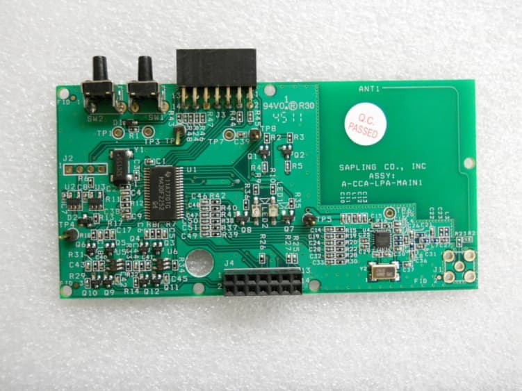
R73LPA1
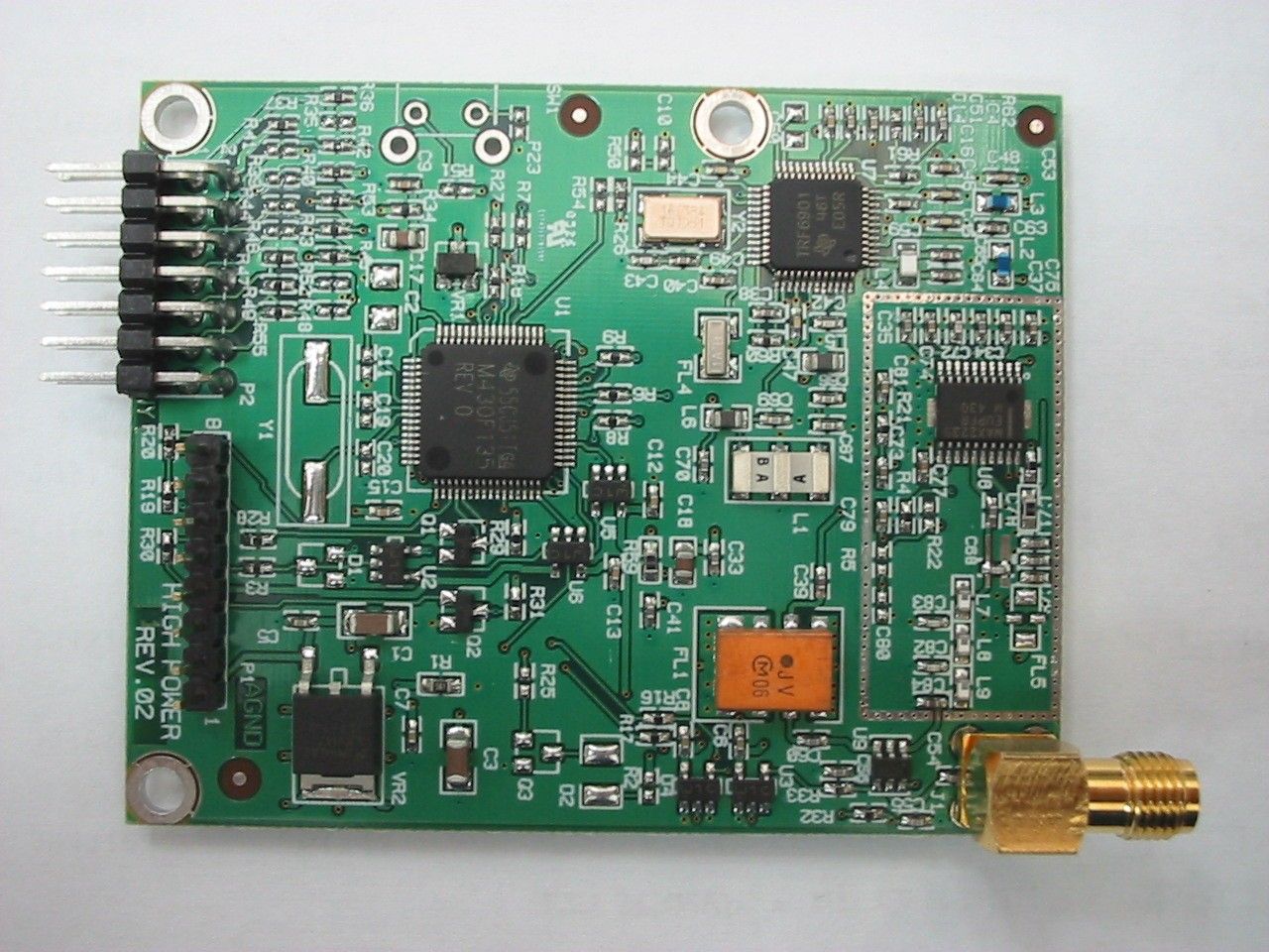
Jun 19, 2012914 TO 928 MHz FREQUENCY HOPPING TRANSCEIVER MODULE
Equipment Class
DSS - Part 15 Spread Spectrum Transmitter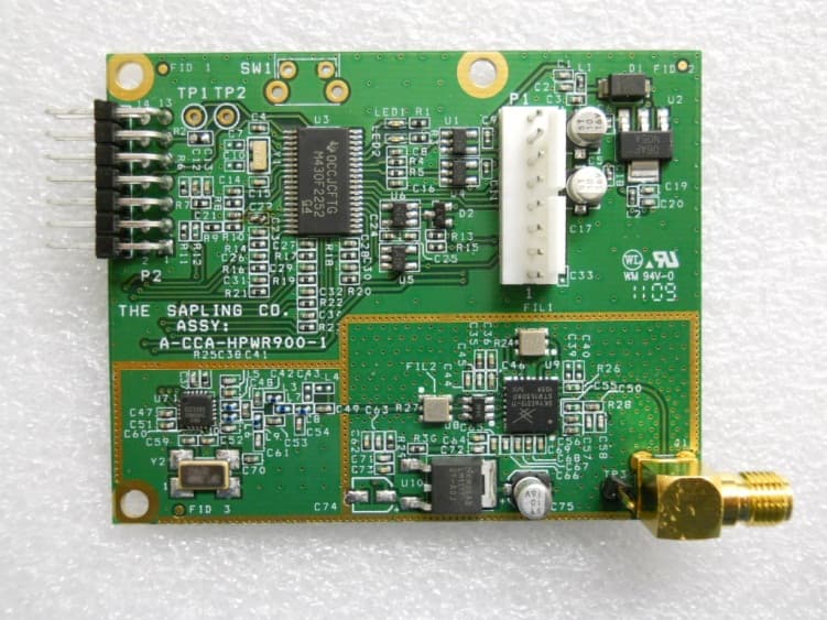
R73HPB1
May 20, 2012914 TO 928 MHz FREQUENCY HOPPING TRANSCEIVER MODULE
Equipment Class
DSS - Part 15 Spread Spectrum Transmitter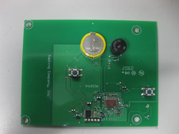
R73ERS003
Jul 04, 2010EMERGENCY RESPONSE SYSTEM (ERS) BATH STATION
Equipment Class
DXX - Part 15 Low Power Communication Device Transmitter