R7TBLUENICECOM3Bluetooth module BlueNiceCom III
Wuerth Elektronik eiSos GmbH & Co KG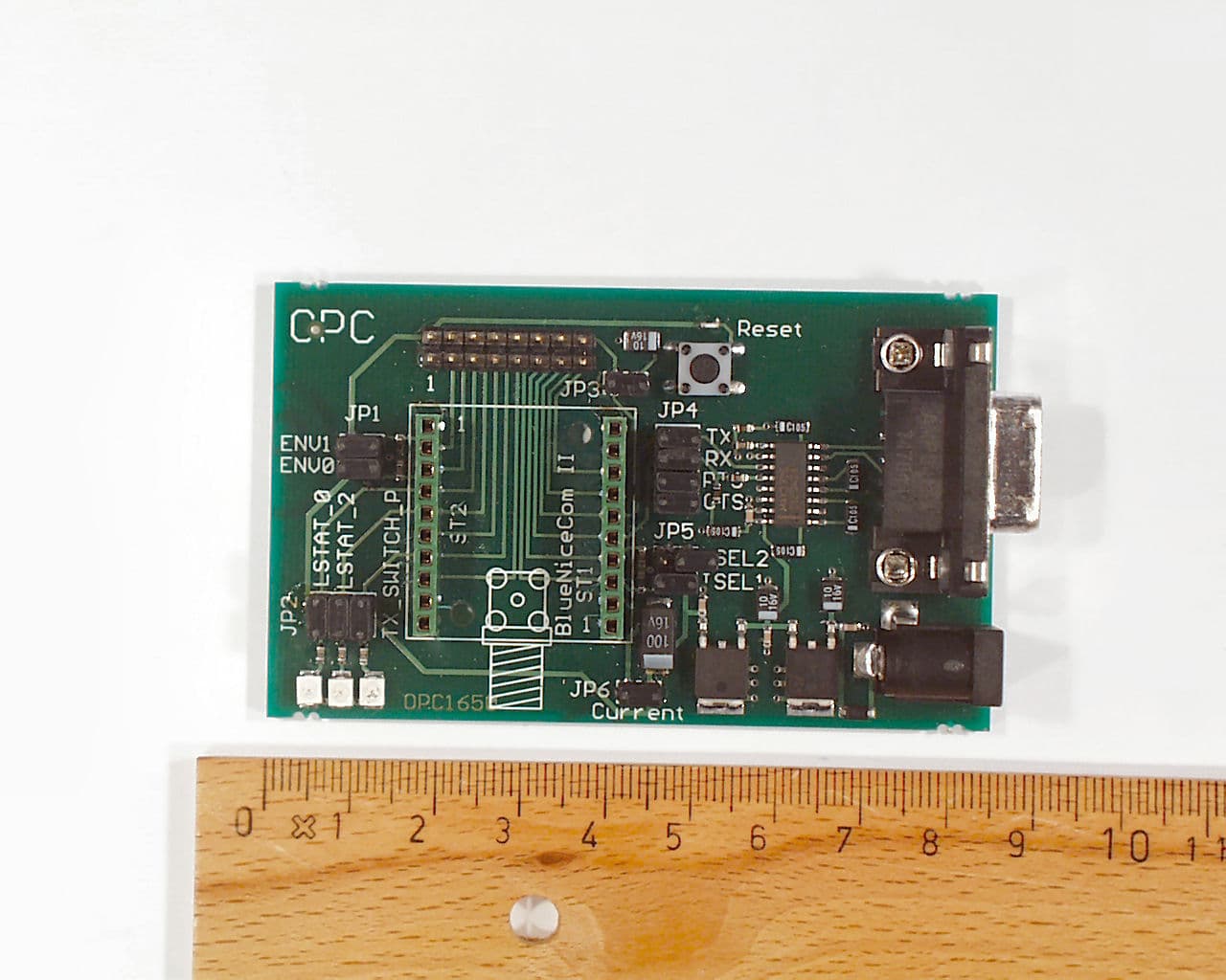
Click to zoom
Application Details
- Equipment Class
- DXX - Part 15 Low Power Communication Device Transmitter
- Date of Grant
- Aug 23, 2005
- Application Purpose
- Original Equipment
- Date of Application
- Aug 23, 2005
- Equipment Note
- Bluetooth module BlueNiceCom III
- Frequency Range
- 2402.00000000 - 2480.00000000
- Country
- Germany
Documents & Files
Document Text
Text extracted from the exhibit documents filed with the FCC. Open a document above to read the original.
Users Manual
Manual BlueNiceCom III V1.4 Stand November 2004 AMBER wireless GmbH Albin-Köbis-Straße 18 51147 Köln Tel. 02203-6991950 Fax 02203-459883 eMail [email protected] Internet www.amber-wireless.de Stand November 2004, Version 1.4 Technische Änderungen vorbehalten AMBER wireless GmbH, Tel. 02203-6991950, Fax 02203-459883 Email info@ amber-wireless.de Internet www.amber-wireless.de Inhaltsverzeichnis 1 Allgemein .......................................................................................Fehler! Textmarke nicht definiert. 2 Technische Daten:.........................................................................Fehler! Textmarke nicht definiert. 3 Anschlussbelegung :..........................................................................................................................4 4 Abmessungen: ...................................................................................................................................5 5 Hinweise zum Layout: ......................................................................................................................6 Stand November 2004, Version 1.4 Technische Änderungen vorbehalten AMBER wireless GmbH, Tel. 02203-6991950, Fax 02203-459883 Email info@ amber-wireless.de Internet www.amber-wireless.de 1 General BlueNiceCom III Bluetooth-Modul with UART-interface and integrated Chip-antenna • Bluetooth Class 2 Modul • Serial Port Profile (SPP) • UART interface • Integrated chip-antenne • GAP & SDP support AMBER wireless provides with the BlueNiceCom III a Bluetooth-module with an integrated chip- antenna, based on LMX9820 from National Semiconductor. This compact and inexpensive Bluetooth- version is qualified for a serial data transmission. BlueNiceCom III comes with a SPP profile (S erial Port Profile) and works with other Bluetooth modules which support the same profile. Through the serial UART interface the BlueNiceCom will be connected to a processor or a direct to a system, according to the application. Via an external processor or host (PC) all further available application profiles could be set on the SPP- profile, for example: Dial up Networking Profile, Fax Profile, LAN Access Profile. The module has an integrated chip-antenna and can placed into a circuit like a SMD-part. The controlling and setting is raised by a host processor. The module can be integrated easily in a system. According to the application and the settings the BlueNiceCom II can be work as a stand-alone-slave- module. For a cable replacement or a point-to-multipoint (piconet) application a controlling through a processor is necessary. Up to 3 slaves could be managed by a master module. 2 Technical data: Voltage supply 2,85V to 3,6V Current consumption typ. 65 mA RF output typ. 0 dBm Rx Sensitivity typ. –77dBm Datarate UART: 9,6 kbps to 115kbps Interface according to LMX9820 Operating temperature -10° bis +55°, optional an extended temperature range is possible Dimension 27,5 x 16 x 3,5 mm Miscellaneous All further technical datas according to the LMX9820 Modul of National Semiconductor Order number BlueNiceCom III Stand November 2004, Version 1.4 Technische Änderungen vorbehalten AMBER wireless GmbH, Tel. 02203-6991950, Fax 02203-459883 Email info@ amber-wireless.de Internet www.amber-wireless.de 3 Pin assignment : ST1 Pin Nr. Signal of BlueNiceCom III Signal of LMX 9820 1 VCC Voltage supply (2,85V bis 3,6V) 2 ISEL1 Input Isel1 of LMX9820 3 ISEL2 Input Isel2 of LMX9820 4 RX Input Uart_rx of LMX9820 5 TX Output Uart_tx of LMX9820 6 RTS Output Uart_rts of LMX9820 7 CTS Input Uart_cts of LMX9820 8 RESET Input Reset_b and Reset_5100 of LMX9820 9 GND Ground 10 ENV1 Input Env1 of LMX9820 11 ENV0 Input Env0 of LMX9820 12 LSTAT_0 Output Lstat_0 of LMX9820 13 LSTAT_1 Output Lstat_1 of LMX9820 14 HOST_WU Output Host_wu of LMX9820 15 TX_SWITCH_P Output TX_Switch_P of LMX9820 16 VDD_DIGI_PWR_D# Input VDD_DIGI_PWR_D# of LMX9820 The signal level correspond to the power supply (2,85V bis 3,6V) of BlueNiceCom III and must be aligned if the Hostsystem has a different signal level. Antenne Stand November 2004, Version 1.4 Technische Änderungen vorbehalten AMBER wireless GmbH, Tel. 02203-6991950, Fax 02203-459883 Email info@ amber-wireless.de Internet www.amber-wireless.de 4 Dimession: BlueNiceCom III has 1mm x 2mm soldering pads with a raster of 2mm to be solder direct on a motherboard. Stand November 2004, Version 1.4 Technische Änderungen vorbehalten AMBER wireless GmbH, Tel. 02203-6991950, Fax 02203-459883 Email info@ amber-wireless.de Internet www.amber-wireless.de 5 Details for Layout: To achieve the maximum of range no metall has to be near or under the antenna. The antenna should have a distance of 8mm to any gound, strip line or component. Most suitable is to place the antenna at the margin of the motherboard. The figure shows the area which should be free of metal (ground, strip line, components, etc..). The area off 12mm between the soldering pads on the bottom side should (e.g. with adhesive tape) additional isolated, if any strip line is under the module to avoid any short circuit. 6 Soldering & Reflow • Reflow appropriate • The temperature curve depends on the motherboard it ́s character. • Depending on the limit values of the components following limits are not allowed to excess- 225°C (LMX) 220°C max. 10s (Chip-antenna) 200°C max. 40s (Chip-antenna) • Recommendation for Footprints: Stand November 2004, Version 1.4 Technische Änderungen vorbehalten AMBER wireless GmbH, Tel. 02203-6991950, Fax 02203-459883 Email info@ amber-wireless.de Internet www.amber-wireless.de Abbildung 1: Bluenicecom III Abbildung 2: Vorschlag for Footprint Further range of products around BlueNiceCom II: Bluetoothmodules: BlueNiceCom I & II & III Evaluation-Kit: 1 BlueNiceCom II module; 1 2,4GHz antenna; 1 RS232 board with Sub-D-9 connector and LED ́s; batteries for power supply; 1 USB-Bluetoothmodule for a second station – to build up a Bluetooth radio link immediately, documen…
Text truncated - open the document above for the full version.
Block Diagram
Annex No.7 Page 1 of 1 Block Diagram : Amber wireless BlueNiceCom III Oscillator frequencies, 12 MHz 20 ppm (Clock) Generated or used frequencies : 12 MHz 20 ppm Lowest frequency declared by the applicant: 2.4020GHz (Channel 1) Middle frequency declared by the applicant: 2.4410GHz (Channel 39) Highest frequency declared by the applicant: 2.4800GHz (Channel 78)
External Photos
Annex No.1 Page 1 of 4 External Photographs of the Equipment Under Test EXTERNAL FRONT VIEW PHOTO Amber wireless BlueNiceCom III Annex No.1 Page 2 of 4 EXTERNAL REAR VIEW PHOTO Annex No.1 Page 3 of 4 External Photographs of the Ancillary equipment EXTERNAL FRONT VIEW PHOTO Evaluation Kit Annex No.1 Page 4 of 4 EXTERNAL REAR VIEW PHOTO
ID Label/Location Info
Annex No.4 Page 1 of 2 FCC ID LABEL SAMPLE FCC ID: R7TBLUENICECOM3 Annex No.4 Page 2 of 2 SKETCH OF FCC ID LABLE LOCATION FCC ID: R7TBLUENICECOM3
Internal Photos
Annex No.1 Page 1 of 4 External Photographs of the Equipment Under Test EXTERNAL FRONT VIEW PHOTO Amber wireless BlueNiceCom III Annex No.1 Page 2 of 4 EXTERNAL REAR VIEW PHOTO Annex No.1 Page 3 of 4 External Photographs of the Ancillary equipment EXTERNAL FRONT VIEW PHOTO Evaluation Kit Annex No.1 Page 4 of 4 EXTERNAL REAR VIEW PHOTO
Operational Description
LMX9820, Revision 1.0, July 24, 2003 2:02 pm © 2003 National Semiconductor Corporationwww.national.com LMX9820 Bluetooth™ Se rial Port Module General Description The National Semiconductor ® LMX9820 Bluetooth™ Serial Port module is a highly integrated radio, baseband control- ler, and memory device implemented on an LTCC (Low Temperature Co-fired Ceramic) substrate. All hardware and firmware is included to provide a complete solution from antenna through the complete lower and upper layers of the Bluetooth stack, up to the application including the Generic Access Profile (GAP), the Service Discovery Application Profile (SDAP), and the Serial Port Profile (SPP). The module includes a configurable service data - base to fulfil service requests for additional profiles on the host. The LMX9820 features a small form factor (10.1 x 14.0 x 1.9 mm) design; thus, solving many of the chal - lenges associated with system integration. Moreover, the LMX9820 is pre-qualified as a Bluetooth Integrated Com- ponent. Conformance testing through the Bluetooth qualifi- cation program enables a short time to market after system integration by insuring a high probability of compliance and interoperability. Based on National’s CompactRISC ™ 16-bit processor architecture and Digital Smart Radio technology, the LMX9820 is optimized to handle the data and link manage- ment processing requirements of a Bluetooth node. The firmware supplied within this device offers a complete Bluetooth (v1.1) stack, including profiles and command interface. This firmware features point-to-point and point- to-multipoint link management supporting data rates up to 723 kbps. The internal memory supports up to three active Bluetooth links. Applications •Personal Digital Assistants •POS Terminals •Data Logging Systems •Any serial data transmission Functional Block Diagram Functional Block Diagram Product Brief July 2003 Revision 1.0 LMX9820 Bluetooth™ Serial Port Module National Semiconductor is a registered trademark and CompactRISC is a trademark of National Semiconductor Corporation. Bluetooth is a trademark of Bluetooth SIG, Inc. and is used under license by National Semiconductor. For a complete listing of National Semiconductor trademarks, please visit www.national.com/trademarks. 2.4 GHz Transceiver Antenna VCC Vo lta ge Regulator UART Bluetooth™ Link Controller AUX 16-bit Risc Controller Command Interface Control Application Serial Port Profile Full Bluetooth™ Stack Flash Memory Por ts Sensor or Microcontroller with User Interface Synthesizer Clock www.national.com2 Revision 1.0 LMX9820 Bluetooth™ Se rial Port Module LMX9820, Revision 1.0, July 24, 2003 2:02 pm Features DIGITAL HARDWARE ■Baseband and Link Management processors ■CompactRISC Core ■Integrated Memory: — Non-volatile data memory — Flash program memory —RAM ■UART Command/Data Port: — Support for up to 921.6k baud rate ■Auxiliary Host Interface Ports: — Link Status — Transceiver Status (Tx or Rx) — Operating Environment Control: –Run mode – In System Programming (ISP) mode ■Advanced Power Management (APM) features FIRMWARE ■Complete Bluetooth Stack including: — Baseband and Link Manager — L2CAP, RFCOMM, SDP — Profiles: –GAP –SDAP – SPP ■Additional Profile support on Host for: – Dial Up Networking (DUN) – Facsimile Profile (FAX) – File Transfer Protocol (FTP) – Object Push Profile (OPP) – Synchronization Profile (SYNC) ■On-chip application including: — Command Interface: – Link setup and configuration (also Multipoint) – Configuration of the module – In system programming – Service database modifications – Default connections — UART Transparent mode — Different Operation modes: – Automatic mode – Command mode DIGITAL SMART RADIO ■Accepts external clock or crystal input: —12 MHz — 20 ppm cumulative clock error required for Bluetooth ■Synthesizer: — Integrated VCO and loop filter — Provides all clocking for radio and baseband func- tions ■Antenna Port (50Ω nominal impedance): — Embedded front-end filter for enhanced out of band performance ■Integrated transmit/receive switch (full duplex operation via antenna port) ■Embedded Balun ■Better than -77 dBm input sensitivity ■0 dBm typical output power PHYSICAL ■10.1 x 14.0 x 1.9 mm ■Complete system interface provided in Land Grid Array on underside for surface mount assembly ■Metal shield included Figure 1. Physical Illustration www.national.com3 Revision 1.0 LMX9820 Bluetooth™ Se rial Port Module LMX9820, Revision 1.0, July 24, 2003 2:02 pm Electrical Specifications GENERAL SPECIFICATIONS Absolute Maximum Ratings (see Ta b l e 1) indicate limits beyond which damage to the device may occur. Operating Ratings (see Ta b l e 2) indicate conditions for which the device is intended to be functional, but do not guarantee specific performance limits. This device is a high performance RF integrated circuit and is ESD sensitive. Handling and assembly of this device should be performed at ESD free workstations. The following conditions are true unless otherwise stated in the tables below: •T A = -40°C to +85°C •VCC = 3.0V Table 1. Absolute Maximum Ratings SymbolParameterMinMaxUnit VCCPower Supply Voltage-0.24.0V V I Voltage on any pad with GND = 0V-0.5VCC + 0.5V RF Input Power+15dBm T S Storage Temperature Range-65+150 o C T L Lead Temperature (solder 4 sec.)+260 o C ESD - Human Body Model2000V Table 2. Recommended Operating Conditions 1 SymbolParameterMinTypMaxUnit VCCModule Power Supply Voltage2.853.33.6V IOVCCI/O Power Supply Voltage2.853.33.6V t R Module Power Supply Rise Time50ms T O Operating Temperature Range-40+85°C Humidity (operating, across operating temperature range) 1090% Humidity (non-operating, 38.7 o C web bulb temperature) 595% 1.Maximum voltage difference allowed between VCC and IOVCC is 500 mV. Table 3. Power Supply Requirements SymbolParameterMinTypMaxUnit I RXSl -115Receive Power Supply Current, Role Slave, transparent UART speed 115.2 kbps 41mA I TXSl -115Transmit Power Supply Current, Role Slave, transparent UAR…
Text truncated - open the document above for the full version.
Test Report
Test Report No.: 05002438 Page 1 of 27 EUT : BlueNiceCom III (Bluetooth Transceiver module) FCC ID: R7TBLUENICECOM3 Date of issue: 2005-06-02 TTI-P-G-128/96 Test Report acc. to the relevant standard: 47 CFR Part 15 C – Intentional Radiators Measurement Procedure: ANSI C63.4 - 1992 relating to AMBER wireless GmbH BlueNiceCom III (Bluetooth Transceiver module) Measurement of Radio- Noise Emissions from Low- Voltage Electrical and Electronic Equipment Technical characteristics and test methods for radio equipment in the frequency range 9 kHz to 40 GHz Test Report No.: 05002438 Page 2 of 27 EUT : BlueNiceCom III (Bluetooth Transceiver module) FCC ID: R7TBLUENICECOM3 Date of issue: 2005-06-02 Manufacturer’s details Manufacturer AMBER wireless GmbH Manufacturer’s grantee code R7T AMBER wireless GmbH Albin-Köbis-Straße 18 D-51147 Köln Germany Tel.: +49 2203 6991950 Fax : +49 2203 459883 Manufacturer’s address E-mail: [email protected] 47 CFR Part 15C - Intentional Radiators Relevant standard used ANSI C63.4-1992 Test Report prepared by Ralf Trepper m.dudde hochfrequenz-technik (laboratory) Rottland 5a D-51429 Bergisch Gladbach Germany Phone: +49 2207 96890 Fax : +49 2207 968920 Technical engineer E-mail: [email protected] Equipment Under Test (EUT) Equipment category Bluetooth Transceiver module Trade name Amber Wireless Type designation BlueNiceCom III Serial no. --- Variants BlueNiceCom III Bluetooth Transceiver module Ancillary equipment none Test Report No.: 05002438 Page 3 of 27 EUT : BlueNiceCom III (Bluetooth Transceiver module) FCC ID: R7TBLUENICECOM3 Date of issue: 2005-06-02 0 Test result CFR Section Report Chapter Requirements Headline Test result OK 15.203 10.1 Antenna requirement pass fail n.a. 15.249 (a) 10.2 Field strength limits (fundamental) pass fail n.a. 15.249(d) 15.209 10.2 Radiated spurious emissions pass fail n.a. 15.207 10.3 Conducted emissions pass fail n.a. 15.215 (c) 10.4 20 dB bandwidth pass fail n.a. Test requirements kept yes no . Signature technician ........................................ Ralf Trepper . Signature manager ......................................... Manfried Dudde Test Report No.: 05002438 Page 4 of 27 EUT : BlueNiceCom III (Bluetooth Transceiver module) FCC ID: R7TBLUENICECOM3 Date of issue: 2005-06-02 List of contents Page 0 Test result .............................................................................................................................................. 3 1 Testing laboratory .................................................................................................................................. 5 2 Introduction........................................................................................................................................... 5 3 Product.................................................................................................................................................. 6 4 Test schedule ......................................................................................................................................... 6 5 Product and measurement documentation............................................................................................... 7 6 Observations and comments................................................................................................................... 7 7 Summary ............................................................................................................................................... 7 8 Conclusions .......................................................................................................................................... 8 9 Operation description............................................................................................................................. 9 10.1 Antenna requirement ......................................................................................................................... 10 10.1.1 Regulation ...................................................................................................................................... 10 10.1.2 Result ............................................................................................................................................. 10 10.2 Radiated emissions ........................................................................................................................... 11 10.2.1 Regulation ...................................................................................................................................... 11 10.2.2 Test equipment ............................................................................................................................... 13 10.2.2 Test procedures............................................................................................................................... 13 10.2.3 Calculation of field strength Section 15.209 below 30 MHz ........................................................... 14 10.2.3 Calculation of field strength Section 15.209 above 30 MHz ........................................................... 14 10.2.4 Calculation of average correction factor.......................................................................................... 14 10.2.5 Calculation of the field strength Section 15.249.............................................................................. 15 10.2.6 Result ............................................................................................................................................. 16 10.2.6 Result ............................................................................................................................................. 18 10.3 Conducted emissions ........................................................................................................................ 21 10.3.1 Regulation .....................................................…
Text truncated - open the document above for the full version.
Test Setup Photos
Annex No.6 Page 1 of 10 Test Setup Photos : Radiated fieldstrength AMBER Wireless GmbH Bluetooth transceiver module BlueNiceCom III Annex No.6 Page 2 of 10 Annex No.6 Page 3 of 10 Annex No.6 Page 4 of 10 Annex No.6 Page 5 of 10 Annex No.6 Page 6 of 10 Annex No.6 Page 7 of 10 Test Setup Photos : Conducted spurious emissions AMBER Wireless GmbH Bluetooth transceiver module BlueNiceCom III Annex No.6 Page 8 of 10 Annex No.6 Page 9 of 10 Annex No.6 Page 10 of 10
Contact Information
Applicant
Gudrun Eckhardt(Manager)
Technical Contact
m.dudde high frequency technologyRalf Trepper
[email protected]+49220796890
Rottland 5A · Bergisch Gladbach · Germany
Test Firm
m. dudde hochfrequenz-technikManfred Dudde
Technical Specifications
| # | Rule Parts | Frequency Range | Power Output |
|---|---|---|---|
| 1 | 15C | 2.40 GHz - 2.48 GHz | - |
Other Applications from Wuerth Elektronik eiSos GmbH & Co KG
R7T1501113
Jun 02, 2026LTE-M / NB-IoT Cellular Module
Equipment Class
PCB - PCS Licensed TransmitterR7T2101102
Sep 04, 2025Bluetooth LE radio module
Equipment Class
DTS - Digital Transmission System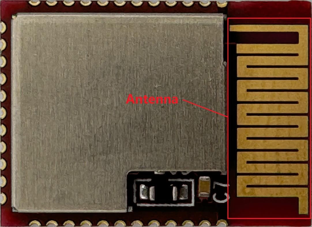
R7T2001102
Sep 04, 2024A Bluetooth module.
Equipment Class
DTS - Digital Transmission System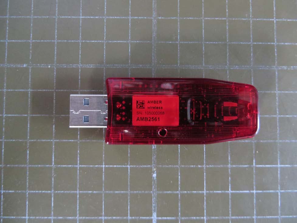
R7TAMB2561
Mar 19, 2015Low Power Transceiver
Equipment Class
DXT - Part 15 Low Power Transceiver, Rx Verified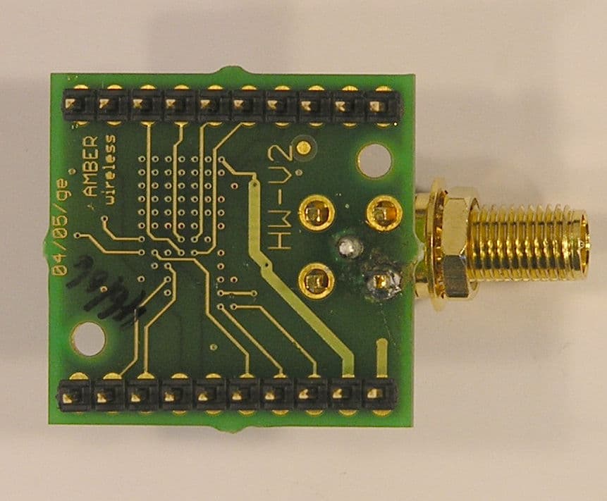
R7TOPC1600
Oct 25, 2007Bluetooth Transceiver Module
Equipment Class
DXX - Part 15 Low Power Communication Device Transmitter