R8N-URM-M-2400MeshNode
Millennial Net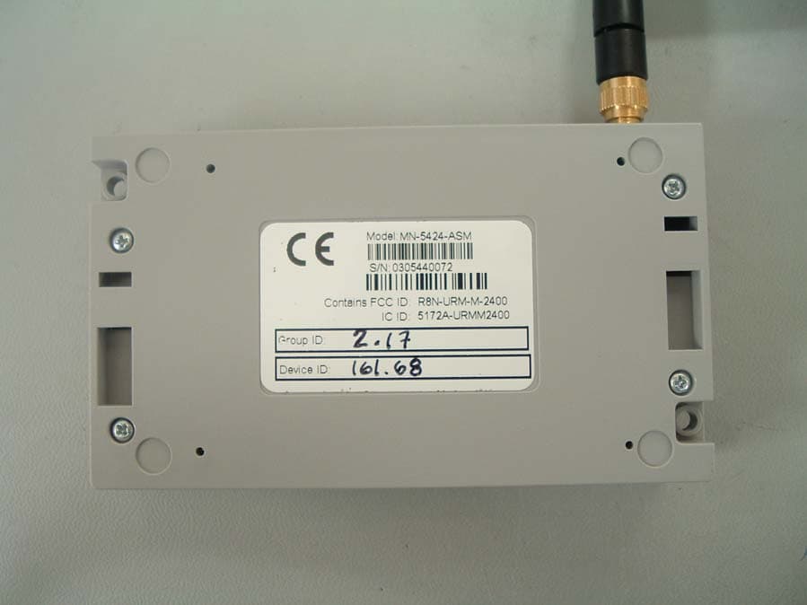
Click to zoom
Application Details
- Equipment Class
- DTS - Digital Transmission System
- Date of Grant
- Jan 02, 2006
- Application Purpose
- Original Equipment
- Date of Application
- Jan 02, 2006
- Equipment Note
- MeshNode
- Frequency Range
- 2400.00000000 - 2483.50000000
- Company
- Millennial Net
- Country
- United States
Documents & Files
Document Text
Text extracted from the exhibit documents filed with the FCC. Open a document above to read the original.
Users Manual
Document Number:DOC-0063 Revision:02 Released:December 2005 MeshScape™ Commercial- and Industrial-class Wireless Sensor Networks RK-5424-5 Reference Kit for 2.4 GHz MeshScape Systems User’s Guide COPYRIGHT This manual is produced and copyrighted by Millennial Net, Inc. Any use or reproduction of the contents of this manual without the prior written consent of Millennial Net, Inc. is strictly prohibited. NOTICE All title and copyrights to this document are owned by Millennial Net, Inc. No part of the contents of this document may be reproduced or transmitted in any form or by any means without the written permission of Millennial Net, Inc. Millennial Net, Inc. shall not be liable for errors contained herein. Millennial Net, Inc. shall not be liable for any damages whatsoever, including, without limitation, damages for loss of business profits, business interruption, loss of business information, or other pecuniary loss arising out of the use of this documentation even if Millennial Net, Inc. has been made aware of the possibility of such damages. Information contained in this document is subject to change without notice. While every effort is made to ensure that the information is accurate as of the publication date, users are reminded to update their use of this document with documents published by Millennial Net, Inc. subsequent to this date. Third-party product information is for informational purposes only, and constitutes neither an endorsement nor a recommendation. Millennial Net, Inc. expressly disclaims any responsibility with respect to the performance of the third-party products. Copyright © 2000 - 2005 by Millennial Net, Inc. ALL RIGHTS RESERVED Printed in U.S.A. Millennial Net, Inc. 2 Fourth Avenue Burlington, MA 01803-3304 USA +1 781.222.1030 RK-5424-5 Reference Kit User’s Guidev CAUTION Initialization of the product should be performed only by a qualified systems administrator. Compliance Statements FCC Compliance FCC compliance for Millennial Net’s RK-5424-5 Reference Kit (2.4GHz, 5-3-1) consisting of the following models/components: •EN-5424 end node •MN-5424 mesh node •MG-5424 MeshGate gateway Compliance Statement (Part 15.19) The Millennial Net RK-5424-5 Reference Kit complies with Part 15 of the FCC Rules and with RSS-210 of Industry Canada. Operation is subject to the following two conditions: (1) This device may not cause harmful interference, and (2) This device must accept any interference received, including interference that may cause undesired operation. Warning (Part 15.21) Changes or modifications not expressly approved by the party responsible for compliance could void the user's authority to operate the equipment. Note (Part 15.105(b)) This equipment has been tested and found to comply with the limits for a Class B digital device, pursuant to part 15 of the FCC Rules. These limits are designed to provide reasonable protection against harmful interference in a residential installation. This equipment generates, uses and can radiate radio frequency energy and, if not installed and used in accordance with the instructions, may cause harmful interference to radio communications. However, there is no guarantee that interference will not occur in a particular installation. If this equipment does cause harmful interference to radio or television reception, which can be determined by turning the equipment off and on, the user is encouraged to try to correct the interference by one or more of the following measures: •Reorient or relocate the receiving antenna. •Increase the separation between the equipment and receiver. •Connect the equipment into an outlet on a circuit different from that to which the receiver is connected. •Consult the dealer or an experienced radio/TV technician for help. viMillennial Net Unlicensed Modular Approval (for OEMs) The URM-G-2400 and URM-M-2400 comply with the FCC's 47CFR Part 15 rules and regulations as well as Part 15 Unlicensed Modular Approval as outlined in DA 00-1407. Compliance with the Modular Approval rules allows an OEM to integrate the URM-G-2400 and URM-M-2400 into other products without further FCC certification of the intentional radiator, but an OEM must still test their final product to comply with unintentional radiator requirements of 47CFCR Part 15. Under the Modular Approval rules, an OEM must comply with the following when integrating the URM-G-2400 and URM-M-2400 into an end product: 1. The OEM must ensure that FCC labeling requirements are met. This shall include a clearly visible label on the exterior of the end product with the following nomenclature: Contains FCC ID: R8N-URM-G-2400 or R8N-URM-M-2400 2. The OEM must only use the reverse polarity-SMA (RP-SMA) antennas listed below when integrating the device into an end product. These antennas have been tested and approved for use with the URM-G-2400 and URM-M-2400. Integrating the module using any other antenna will require testing to ensure compliance with FCC rules and regulations. Centurion ½ wave Antenna Part Number: WCR2400SMRP 3. The OEM must use the same cable type and of the same length or longer than that defined below. Use of another cable type or of a shorter length will require testing to ensure compliance with FCC rules and regulations. RF Cable type: RG174 RF Cable Length: 5.9" +/- 0.13” Millennial Net Cable P/N: CBL-0018-01 Industry Canada Compliance Statement This device has been designed to operate with an antenna having a maximum gain of 2.65 dB. Antenna having a higher gain is strictly prohibited per regulations of Industry Canada. The required antenna impedance is 50 Ohms. To reduce potential radio interference to other users, the antenna type and its gain should be so chosen that the equivalent isotropically radiated power (EIRP) is not more than that required for successful communication. OEM Integration The modules have the same requirements for integration into an OEM product for Industry Canada as it does for FCC. The only difference bei…
Text truncated - open the document above for the full version.
Cover Letter(s)
Millennial Net 2 Fourth Avenue Burlington, MA 01803 (781-222-1030) www.millennialnet.com July 25 th , 2005 Attn: Reviewing Engineer Federal Communications Commission 7435 Oakland Mills Road Columbia, MD21046 The following outlines how Millennial Net’s URM-M-2400 module meets the FCC’s 8 requirements for modular approval. 1.) The modular transmitter must have its own RF shielding. This is intended to ensure that the module does not have to rely upon the shielding provided by the device into which it is installed in order for all modular transmitter emissions to comply with Part 15 limits. It is also intended to prevent coupling between the RF circuitry of the module and any wires or circuits in the device into which the module is installed. Such coupling may result in non-compliant operation. The URM-M-2400 device is equipped with an RF shield that physically encompasses the entire RF circuit, from the digital input all the way to the MMCX RF connector on the edge of the module. The RF shield provides not only immunity to external signals but will comply with all Part 15 limits. 2.) The modular transmitter must have buffered modulation/data inputs (if such inputs are provided) to ensure that the module will comply with Part 15 requirements under conditions of excessive data rates or over-modulation. All data inputs to the URM-M-2400 are interfaced or controlled by the on-bord microcontroller. There are no direct connections between the external interfaces of the module and the modulation circuits within the radio. The microcontroller controls all Network/Protocol processing and buffers all externally generated data prior to transmission, as such the radio will never experience excessive data rates or over-modulation. A block diagram of the module is included in the submittal package. 3.) The modular transmitter must have its own power supply regulation. This is intended to ensure that the module will comply with Part 15 requirements regardless of the design of the power supplying circuitry in the device into which the module is installed. Millennial Net 2 Fourth Avenue Burlington, MA 01803 (781-222-1030) www.millennialnet.com The URM-M-2400 contains an on-board voltage regulator which is used to provide the local power to all the on-board circuits. The operating voltage of the module is specified for 3.3 ± 5%. 4.) The modular transmitter must comply with the antenna requirements of Section 15.203 and 15.204(c). The antenna must either be permanently attached or employ a “unique” antenna coupler (at all connections between the module and the antenna, including the cable). Any antenna used with the module must be approved with the module, either at the time of initial authorization or through a Class II permissive change. The “professional installation” provision of Section 15.203 may not be applied to modules. The URM-M-2400 is equipped with a board mounted MMCX connector for use in attaching an external antenna. External antennas are attached via a coax cable assembly with the corresponding MMCX mating connector on one end and a Reverse Polarity SMA jack on the other end. The test report will detail the various antennas the module was tested with along with the cable used for testing. 5.) The modular transmitter must be tested in a stand-alone configuration, i.e., the module must not be inside another device during testing. This is intended to demonstrate that the module is capable of complying with Part 15 emission limits regardless of the device into which it is eventually installed. Unless the transmitter module will be battery powered, it must comply with the AC line conducted requirements found in Section 15.207. AC or DC power lines and data input/output lines connected to the module must not contain ferrites, unless they will be marketed with the module (see Section 15.27(a)). The length of these lines shall be length typical of actual use or, if that length is unknown, at least 10 centimeters to insure that there is no coupling between the case of the module and supporting equipment. Any accessories, peripherals, or support equipment connected to the module during testing shall be unmodified or commercially available (see Section 15.31(i)). The URM-M-2400 is able to be tested in a standalone configuration where only power is supplied via feed wires. The module is DC powered. There are no ferrites located on the power supply feed lines. 6.) The modular transmitter must be labeled with its own FCC ID number, and, if the FCC ID is not visible when the module is installed inside another device, then the outside of the device into which the module is installed must also display a label referring to the enclosed module. This exterior label can use wording such as the following: “Contains Transmitter Module FCC ID: XYZMODEL1” or “Contains FCC ID: XYZMODEL1.” Any similar wording that expresses the same meaning may be used. The Grantee may either provide such a label, an example of which must be Millennial Net 2 Fourth Avenue Burlington, MA 01803 (781-222-1030) www.millennialnet.com included in the application for equipment authorization, or, must provide adequate instructions along with the module which explain this requirement. In the latter case, a copy of these instructions must be included in the application for equipment authorization. The URM-M-2400 will be labeled as “FCC ID: R8N-URM-M-2400” on the RF shield. Examples of the labeling used on the module and the device this is integrated into will be included in the submittal package. The users guide also outlines the labeling requirements when embedding this module. 7.) The modular transmitter must comply with any specific rule or operating requirements applicable to the transmitter and the manufacturer must provide adequate instructions along with the module to explain any such requirements. A copy of these instructions must be included in the application for equipment authorization. For example, there are very strict operational a…
Text truncated - open the document above for the full version.
External Photos
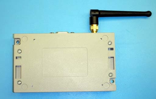
Millennial Net 2 Fourth Avenue Burlington, MA 01803 (781-222-1030) www.millennialnet.com Bottom Labeling Millennial Net 2 Fourth Avenue Burlington, MA 01803 (781-222-1030) www.millennialnet.com MN-5424 TOP Photo MN-5424 Face Plate
ID Label/Location Info
Millennial Net 2 Fourth Avenue Burlington, MA 01803 (781-222-1030) www.millennialnet.com MN-5424 Labeling The following illustration depicts the MN-5424 product label: The label is X.XX” x X.XX” in size and is printed on XXX material. The label is placed on the MN5424 device in the indentation located on the bottom of the enclosure. The following photo depicts the indentation on the enclosure: Millennial Net 2 Fourth Avenue Burlington, MA 01803 (781-222-1030) www.millennialnet.com URM-M-2400 Labeling The following label is placed onto the RF shield of the URM. Since the URM is smaller than 8 x 10 cm, the label only contains the FCC and IC IDs: The following photo depicts the RF shield, metallic area with the RF cable emanating from the side) on which this label is to be applied:
ID Label/Location Info
MN-5424 Front Panel MN-5424 Internal Photo MN-5424 Labeling Area MN-5424 Top Photo
Internal Photos
Millennial Net 2 Fourth Avenue Burlington, MA 01803 (781-222-1030) www.millennialnet.com URM-M-2400 Top Millennial Net 2 Fourth Avenue Burlington, MA 01803 (781-222-1030) www.millennialnet.com URM-M-2400 Bottom Millennial Net 2 Fourth Avenue Burlington, MA 01803 (781-222-1030) www.millennialnet.com MN-5424 Internal Photo Millennial Net 2 Fourth Avenue Burlington, MA 01803 (781-222-1030) www.millennialnet.com MN-5424 Terminal Board Bottom Millennial Net 2 Fourth Avenue Burlington, MA 01803 (781-222-1030) www.millennialnet.com MN-5424 Internal photo Millennial Net 2 Fourth Avenue Burlington, MA 01803 (781-222-1030) www.millennialnet.com Enclosure Internal photo
Test Report
Emissions Report for Millennial Net, Inc. on the MeshNode, Model MN-5424 Report Number 3084942BOX.005 Page 2 of 107 1.0 Job Description 1.1 Client Information This EUT has been tested at the request of Company: Millennial Net, Inc. 2 Fourth Avenue Burlington, MA 01803 Contact: Dave Oswill Telephone: Fax: 781-222-1030 781-222-1039 1.2 Equipment Under Test Equipment Type: MeshNode Model Number(s): MN-5424 Serial number(s): 405360044 Manufacturer: Millennial Net, Inc. EUT receive date: 10/11/2005 EUT received condition: Good Test start date: 10/11/2005 Test end date: 10/27/2005 1.3 Test Plan Reference: Tested according to the standards listed and ANSI C63.4:2003. 1.4 Test Configuration 1.4.1 Block Diagram Turntable MeshNode PC Board 2x DC Power Wires from AC->DC Power Supply Emissions Report for Millennial Net, Inc. on the MeshNode, Model MN-5424 Report Number 3084942BOX.005 Page 3 of 107 1.4.2 Cable List: Cable Shielding Connector Length (m) Qty. DC Power None Wire 2 1 1.4.3 Support Equipment: Name: Model No.: Serial No.: UNIFIVE AC-DC Power Supply UL305-3315 408-0021815 1.5 Mode of Operation: The EUT was operated as a module, with 3.0VDC power applied from a power supply running at 120V/60Hz AC power. The EUT was transmitting continuously throughout testing. Emissions Report for Millennial Net, Inc. on the MeshNode, Model MN-5424 Report Number 3084942BOX.005 Page 4 of 107 2.0 Test Summary TEST STANDARD RESULTS FCC Part 15 Subpart C 15.247 SUB-TEST TEST PARAMETER COMMENT Occupied Bandwidth FCC 15.247(a)(2) The 6 dB bandwidth must be at least 500 kHz. Pass Maximum Peak Conducted Output Power and Human RF Exposure FCC 15.247(b)(3-5) The output power must not exceed 1 Watt (30 dBm) and 36 dBm EIRP. The human RF Exposure limit is 1 mW/cm 2 . Pass Antenna Port Conducted Spurious Emissions FCC 15.209, 15.247(d) The spurious emissions must be attenuated below the level of the fundamental by at least 20 dBc. Pass Radiated Spurious Emissions FCC 15.205, 15.209, 15.247(d) The spurious emissions must be attenuated below the level of the fundamental by at least 20 dBc. Emissions which fall in the restricted bands must meet the general limits of 15.209. Pass Peak Power Spectral Density FCC 15.247(e) The peak power spectral density must not exceed 8 dBm / 3 kHz. Pass Band Edge Compliance FCC 15.215 The fundamental frequency must stay within the assigned frequency band. Pass AC Line-Conducted Emissions FCC 15.207 The AC line-conducted emissions must not exceed the limits of 15.207. Pass Notes: The EUT was tested as a module. The channels selected for test were channels 11, 18, and 26. Channel 11: 2405 MHz Channel 18: 2440 MHz Channel 26: 2480 MHz Emissions Report for Millennial Net, Inc. on the MeshNode, Model MN-5424 Report Number 3084942BOX.005 Page 5 of 107 3.0 Sample Calculations The field strength is calculated by adding the Antenna Factor and Cable Factor, and subtracting the Amplifier Gain (if any) from the measured reading. The basic equation with a sample calculation is as follows: FS = RA + AF + CF - AG Where FS = Field Strength in dBμV/m RA = Receiver Amplitude (including preamplifier) in dBμV CF = Cable Attenuation Factor in dB AF = Antenna Factor in dB AG = Amplifier Gain in dB In the following table(s), the reading shown on the data table reflects the preamplifier gain. An example for the calculations in the following table is as follows. Assume a receiver reading of 52.0 dBμV is obtained. The antenna factor of 7.4 dB and cable factor of 1.6 dB is added. The amplifier gain of 29 dB is subtracted, giving a field strength of 32 dBμV/m. This value in dBμV/m was converted to its corresponding level in μV/m. RA = 52.0 dBμV AF = 7.4 dB/m CF = 1.6 dB AG = 29.0 dB FS = 32 dBμV/m Level in μV/m = [10( 32 dBμV/m)/20] = 39.8 μV/m The following is how net line-conducted readings were determined: NF = RF + LF + CF + AF Where NF = Net Reading in dBμV RF = Reading from receiver in dBμV LF = LISN Correction Factor in dB CF = Cable Correction Factor in dB AF = Attenuator Loss Factor in dB To convert from dBμV to μV or mV the following was used: UF = 10 (NF / 20) where UF = Net Reading in μV Example: NF = RF + LF + CF + AF = 28.5 + 0.2 + 0.4 + 20.0 = 49.1 dBμV UF = 10 (48.1 dBμV / 20) = 254 μV/m Emissions Report for Millennial Net, Inc. on the MeshNode, Model MN-5424 Report Number 3084942BOX.005 Page 6 of 107 3.1 Measurement Uncertainty Compliance of the product is based on the measured value. However, the measurement uncertainty is included for informational purposes. The expanded uncertainty (k = 2) for radiated emissions from 30 to 1000 MHz has been determined to be: ±3.5 dB at 10m, ±3.8 dB at 3m The expanded uncertainty (k = 2) for mains conducted emissions from 150 kHz to 30 MHz has been determined to be: ±2.6 dB The expanded uncertainty (k = 2) for telecom port conducted emissions from 150 kHz to 30 MHz has been determined to be: ±3.2 for ISN and voltage probe measurements ±3.1 for current probe measurements Emissions Report for Millennial Net, Inc. on the MeshNode, Model MN-5424 Report Number 3084942BOX.005 Page 7 of 107 3.2 Site Description Test Site(s): 2 Our OATS are 3m and 10m sheltered emissions measurement ranges located in a light commercial environment in Boxborough, Massachusetts. They meet the technical requirements of ANSI C63.4-2003 and CISPR 22:1993/EN 55022:1994 for radiated and conducted emission measurements. The shelter structure is entirely fiberglass and plastic, with outside dimensions of 33 ft x 57 ft. The structure resembles a quonset hut with a center ceiling height of 16.5 ft. The testing floor is covered by a galvanized sheet metal groundplane that is earth-grounded via copper rods around the perimeter of the site. The joints between individual metal sheets are bridged with a 2 inch wide metal strips to provide low RF impedance contact throughout. The sheets are screwed in place with stainless steel, round-head screws every three inches. Site illumination and HVAC are provided …
Text truncated - open the document above for the full version.
Test Setup Photos
Emissions Report for Millennial Net, Inc. on the MeshNode, Model MN-5424 Report Number 3084942BOX.005 Page 95 of 107 Setup Photos Emissions Report for Millennial Net, Inc. on the MeshNode, Model MN-5424 Report Number 3084942BOX.005 Page 96 of 107
Contact Information
Applicant
Mark Urbin(Director of Quality Assurance)
Technical Contact
Millennial NetDavid E Oswill
[email protected](781) 222-1030
2 Forth Avenue · Burlington, Massachusetts · United States
Non-Technical Contact
Millennial NetDavid E Oswill
[email protected](781) 222-1030
Test Firm
Intertek Testing Services NA Inc.Yaqing Liu
[email protected]978 635 8662
Technical Specifications
| # | Rule Parts | Frequency Range | Power Output |
|---|---|---|---|
| 1 | 15C | 2.40 GHz - 2.48 GHz | 2.00 mW |
Other Applications from Millennial Net
R8N-MG5424XL
Mar 31, 2008MeshNode
Equipment Class
DTS - Digital Transmission System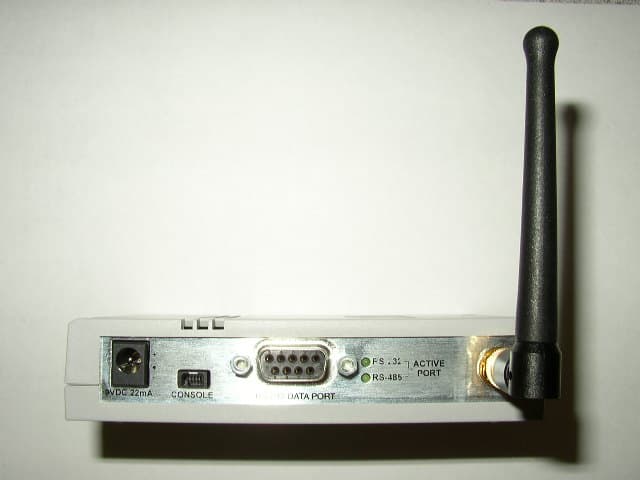
R8N-URM-G-2400
Jan 02, 2006MeshGate
Equipment Class
DTS - Digital Transmission System
R8N-URM-G-916
Nov 07, 2005Transmitter Module
Equipment Class
DXX - Part 15 Low Power Communication Device Transmitter
R8N-IB-5209ENC
Aug 31, 2004Wireless Sensor Networking Device
Equipment Class
DXX - Part 15 Low Power Communication Device Transmitter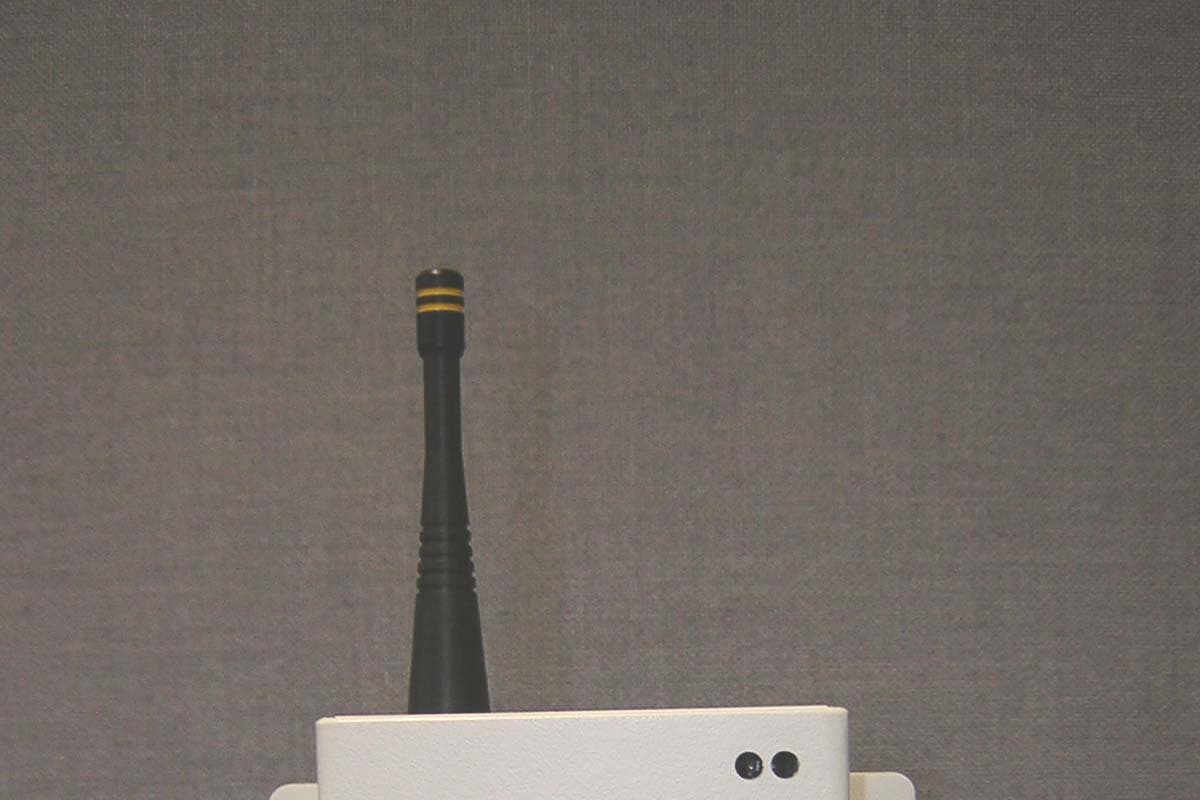
R8N-GW-5209
Aug 26, 2004Wireless Sensor Networking Device
Equipment Class
DXX - Part 15 Low Power Communication Device Transmitter