RAY3G4GFMCW RADAR WITH LINEAR FREQUENCY SWEEP
Navico Inc.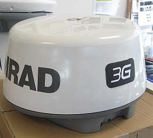
Click to zoom
Application Details
- Equipment Class
- MRD - Marine Radar
- Date of Grant
- Mar 27, 2011
- Application Purpose
- Original Equipment
- Date of Application
- Mar 27, 2011
- Equipment Note
- FMCW RADAR WITH LINEAR FREQUENCY SWEEP
- Frequency Range
- 9300.00000000 - 9400.00000000
- Company
- Navico Inc.
- Country
- United States
Documents & Files
Document Text
Text extracted from the exhibit documents filed with the FCC. Open a document above to read the original.
Users Manual
ENGLISH Broadband 3G™ Radar Installation Guide www.bandg.com www.simrad-yachting.com www.lowrance.com 2 | Broadband 3G™ Radar Installation Guide BLANK PAGE | 3 Contents | Broadband 3G™ Radar Installation Guide Contents 6 Welcome 6 What is Broadband radar? 6 FMCW radar is diff erent: 6 How does FMCW radar work? 7 Additional benefi ts of FMCW radar are: 8 Radar system overview 10 Installation 10 Tools Required 10 Choose the scanner location 11 Considerations for direct roof mounting 14 Connect interconnection cable to the scanner 15 Connect the interconnection cable to radar interface box 17 Connect the Broadband radar to your display 17 Lowrance HDS USA 18 Lowrance HDS Outside USA or with MARPA / Chart overlay 18 Simrad NSS (NMEA2000 network) 19 B & G Ze us 19 Simrad NSO, NSE and NSS, (SimNet network) 20 RI10 Connections 21 Connect power 22 Setup and Confi guration 22 Entering radar setup on your display 22 Radar Status 23 Adjust bearing alignment... 23 Adjust local interference reject 23 Adjust antenna height 23 Sidelobe suppression 24 To start the radar 24 RI10 heading source selection 24 Dual radar setup: 26 Dimension Drawings 26 Scanner 27 Radar interface box 27 Maintenance 28 Specifi cations 29 Navico Broadband radar part numbers 30 RF exposure compliance certifi cate 4 | Contents | Broadband 3G™ Radar Installation Guide Industry Canada Operation is subject to the following two conditions: (1) this device may not cause interference, and (2) this device must accept any interference, including interference that may cause undesired operation of the device. FCC Statement Note: This equipment has been tested and complies with the limits for a Class B digital device, pursuant to Part 15 of the FCC Rules. These limits are designed to provide reasonable protection against harmful interference in a normal installation. This equipment generates, uses and can radiate radio frequency energy and, if not installed and used in accordance with the instructions, may cause harmful interference to radio communications. However, there is no guarantee that interference will not occur in a particular installation. This device must ac- cept any interference received, including interference that may cause undesired operation. If this equipment does cause harmful interference to radio or television reception, which can be determined by turning the equipment off and on, the user is encouraged to try to correct the interference by one or more of the following measures: Reorient or relocate the receiving antenna. Increase the separation between the equipment and receiver. Connect the equipment into an output on a circuit diff erent from that to which the receiver is connected. Consult the dealer or an experienced technician for help. Note: A shielded cable must be used when connecting a peripheral to the serial ports. Changes or modifi cations not expressly approved by the manufacturer could void the user’s authority to operate the equipment. CE Compliance The equipment named in this declaration, is intended for use in international waters as well as coastal sea areas administered by countries of the E.U. and E.E.A. Radar Transmit Emissions Note: Broadband 3G™ Radar is the second generation marine recreational radar from Navico that has Human Exposure Level RF Radiation of the Radar Transmitter outside the Radome well below the general public safety emission level of 1 mW/cm 2 . This means the radar can be mounted safely in locations impossible with other pulse radars. Note: If a pulse radar and Broadband radar are mounted on the same vessel, do not transmit simultaneously as excessive interference is possible. The broadband radar will not trigger X Band radar transponders, beacons, and SARTs due to the low output power and signal properties. ! | 5 Welcome | Broadband 3G™ Radar Installation Guide Disclaimer As Navico is continuously improving this product, we retain the right to make changes to the product at any time which may not be refl ected in this version of the manual. Please contact your nearest distributor if you require any further assistance. It is the owner’s sole responsibility to install and use the instrument and transducers in a man- ner that will not cause accidents, personal injury or property damage. The user of this product is solely responsible for observing safe boating practices. NAVICO HOLDING AS. AND ITS SUBSIDIARIES, BRANCHES AND AFFILIATES DISCLAIM ALL LI- ABILITY FOR ANY USE OF THIS PRODUCT IN A WAY THAT MAY CAUSE ACCIDENTS, DAMAGE OR THAT MAY VIOLATE THE LAW. Governing Language: This statement, any instruction manuals, user guides and other informa- tion relating to the product (Documentation) may be translated to, or has been translated from, another language (Translation). In the event of any confl ict between any Translation of the Documentation, the English language version of the Documentation will be the offi cial version of the Documentation. This manual represents the product as at the time of printing. Navico Holding AS. and its sub- sidiaries, branches and affi liates reserve the right to make changes to specifi cations without notice. Copyright © 2011 Navico Holding AS. W arranty The warranty card is supplied as a separate document. In case of any queries, refer to the brand web site of your display or system. www.lowrance.com www.simrad-yachting.com www.BandG.com 6 | Welcome | Broadband 3G™ Radar Installation Guide Welcome Congratulations of your purchase of the latest technology available in recreational marine radar. The special features designed into this radar are: “Revolutionary improvement in situational awareness” Provides unprecedented ability to distinguish hazards and other objects Radar is fi nally easy enough for casual users – identifi es targets clearly with out complicated tuning adjustments. Navigation with unparalleled resolution and clarity at close ranges, where traditional radar completely obscures targets. “Start faster, go longer” - 100% solid s…
Text truncated - open the document above for the full version.
Users Manual
NAVICO CONFIDENTIAL – PRE-RELEASE INFORMATION Broadband 3G TM Radar - Specifications REV:0.05 Characteristic Technical Data General Compliance CE, FCC (ID: RAY3G4G), IC: 4697A-3G4G Environmental IEC60945 4th edition 2002-2008 Operating Temperature: -25° to +55°C (-13° to +130°F) Relative humidity: +35° C (95° F), 95% RH Waterproof: IPX6 Relative wind velocity 51 m/sec (Max:100 Knots) Power consumption (with 10m cable) Operating: 18W (Typ.) @ 13.8Vdc Standby: 2W (Typ.) @ 13.8Vdc ~ 150mA DC input (at end of radar cable) 9V to 31.2Vdc (12/24 Volt systems). Reverse polarity protection Transmitter source (pre-heating time ) No magnetron – Instant On™ Outside dimensions Height 280 mm x Diameter 489 mm (Height 11" x Diameter 19.3" ) Scanner weight (no cable) 7.4 kg (16.31 lbs) Radar and Antenna Parameters Radar ranges 50 m (200 ft) to 24 nm with 17 range settings (nm/sm/km) Rotation (mode dependent) 24/36 rpm +/-10% Transmitter frequency X-band - 9.3 to 9.4Ghz Transmitter source (warm-up time) No Magnetron – all solid state. Instant On™ Plane of polarization Horizontal Polarization Transmitter peak power output 165mW (nominal) Main bang dead zone & tuning None – not a pulse radar Sea and rain clutter 5X less than a pulse radar Sweep repetition frequency 200Hz Sweep time 1.3ms+/- 10% Sweep bandwidth 75 MHz max Horizontal beam width (Tx and Rx antenna) 5.2°+/-10% (-3dB width) Vertical beam width (Tx and Rx antenna) 25°+/-20% (-3dB width) Side lobe level (Tx and Rx antenna) Below -18dB (within ±10°);Below -24dB (outside ±10°) Noise figure Less than 6dB Coms/Cabling/Mounting Com protocol High Speed Ethernet and Serial Heading NMEA0183 / NMEA2000 / SimNet with interface box Inter connecting cable length Lowrance 10 m (33 ft) Simrad, B&G 20 m (65.6 ft) Maximum inter connecting cable length 30 m (98.5 ft) – available as option Bolts (4) M8x30 - 304 stainless steel Footprint W233 mm (9.17") (port / starboard) x L141.5 mm (5.55") (matches Garmin GMR18HD / Raymarine RD218 footprint) Compatible Displays Simrad: Lowrance: B&G: NSE/NSO HDS 5”, 7”, 8”, 10" Zeus 8" & 12" ** Specifications subject to change without notice. ** NAVICO CONFIDENTIAL – PRE-RELEASE INFORMATION 280mm Tall 488mm Wide
Users Manual
NAVICO CONFIDENTIAL – PRE-RELEASE INFORMATION Broadband 4G TM Radar - Specifications REV:0.04 Characteristic Technical Data General Compliance CE, FCC (ID: RAY3G4G), IC: 4697A-3G4G Environmental IEC60945 4th edition 2002-2008 Operating Temperature: -25° to +55°C (-13° to +130°F) Relative humidity: +35° C (95° F), 95% RH Waterproof: IPX6 Relative wind velocity 51 m/sec (Max:100 Knots) Power consumption (with 10m cable) Operating: 20W (Typ.) @ 13.8Vdc Standby: 2.5W (Typ.) @ 13.8Vdc ~ 170mA DC input (at end of radar cable) 9V to 31.2Vdc (12/24 Volt systems). Reverse polarity protection Transmitter source (pre-heating time ) No magnetron – Instant On™ Outside dimensions Height 280 mm x Diameter 489 mm (Height 11" x Diameter 19.3" ) Scanner weight (no cable) 7.4 kg (16.31 lbs) Radar and Antenna Parameters Radar ranges 50 m (200 ft) to 24 nm with 17 range settings (nm/sm/km) Rotation 24/36/48 rpm +/-10% (mode dependent) Transmitter frequency X-band - 9.3 to 9.4Ghz Transmitter source (warm-up time) No Magnetron – all solid state. Instant On™ Plane of polarization Horizontal Polarization Transmitter peak power output 165mW (nominal) Main bang dead zone & tuning None – not a pulse radar Sea and rain clutter 5X less than a pulse radar Sweep repetition frequency 200 – 540Hz (mode dependant) Sweep time 1.3ms+/- 10% Sweep bandwidth 75 MHz max Horizontal beam width (Tx and Rx antenna) 5.2°+/-10% (-3dB width) Vertical beam width (Tx and Rx antenna) 25°+/-20% (-3dB width) Side lobe level (Tx and Rx antenna) Below -18dB (within ±10°);Below -24dB (outside ±10°) Noise figure Less than 6dB Coms/Cabling/Mounting Com protocol High Speed Ethernet and Serial Heading NMEA0183 / NMEA2000 / SimNet with interface box Inter connecting cable length Lowrance 10 m (33 ft) Simrad, B&G 20 m (65.6 ft) Maximum inter connecting cable length 30 m (98.5 ft) – available as option Bolts (4) M8x30 - 304 stainless steel Footprint W233 mm (9.17") (port / starboard) x L141.5 mm (5.55") (matches Garmin GMR18HD / Raymarine RD218 footprint) Compatible Displays Simrad: Lowrance: B&G: NSE/NSO HDS 5”, 7”, 8”, 10" Zeus 8" & 12" ** Specifications subject to change without notice. ** NAVICO CONFIDENTIAL – PRE-RELEASE INFORMATION 280mm Tall 488mm Wide
Cover Letter(s)
March 21, 2011 Federal Communications Commission Authorization and Evaluation Division Confidentiality Request regarding application for certification of FCC ID: RAY3G4G Pursuant to Sections 0.457 and 0.459 of the Commission’s Rules, we hereby request confidential treatment of information accompanying this application as outlined below: Exhibits Description Exhibits Name.extension • Block Diagram/Schematics Navico_Wahoo_Schematic_with_Blockdiagrams.pdf • Operational Description Navico Broadband Radar_Operational Description.pdf • Parts List Navico_Wahoo_BOM.pdf • Tune Up Procedure 3G_4G Broadband Radar_NAX_X_002v2 report.pdf The above materials contain trade secrets and proprietary information not customarily released to the public. The public disclosure of these materials may be harmful to the applicant and provide unjustified benefits to its competitors. Pursuant to DA 04-1705 June 15, 2004 of the Commission’s public notice, we also request temporary confidential treatment of information accompanying this application for maximum allowed 180 days as outlined below: Exhibits Description Exhibits Name.extension • Test Setup Photos 2877AT10_Setup.pdf • External Photos RAY3G4G_External_pictures.pdf • Internal Photos RAY3G4G_Internal_pictures.pdf • Internal PCB Photos RAY3G4G_Internal_PCBs.pdf • Users/Installation Manual Broadband_Radar IM_EN_MN000760D_W.pdf • Specifications WAHOO Radar Specifications_3G.pdf WAHOO Radar Specifications_4G.pdf Sincerely, John Scott COO Navico Auckland Limited
External Photos
Confidential – Navico Auckland Limited RAY3G4G_External_pictures.docx Broadband 3G™ / 4G™ Radar Broadband 3G™ / 4G™ Radar ‐ underside Broadband 3G™ / 4G™ Radar ‐ Top Broadband 3G™ Radar Broadband 4G™ Radar
ID Label/Location Info
WAHOO BROADBAND RADAR Serial number details There will be two models of WAHOO Broadband Radar: • 3G or ENTRY level • 4Gx or PREMIUM level Serial number labels – actual size: Serial number label – location:
Internal Photos
Confidential – Navico Auckland Limited RAY3G4G_Internal_PCBs.docx Microwave PCB Microwave PCB Main CPU PCB ‐ Top Main CPU PCB ‐ Bottom Main Rotary Joint PCB ‐ Top Main Rotary Joint PCB ‐ Bottom
Internal Photos
Confidential – Navico Auckland Limited RAY3G4G_Internal_pictures.docx Internal main assembly ‐ front Internal main assembly ‐ back Internal main assembly ‐ front Internal main assembly ‐ back Internal main assembly – motor & rotary joint Internal main assembly – drive belt and pulleys
Test Report
FCC PART 80, 90 AND IC RSS-138 TEST REPORT APPLICANT NAVICO AUCKLAND LTD 3-5 OMEGA STREET ALBANY 0632 AUCKLAND NEW ZEALAND FCC ID RAY3G4G IC CERTIFICATION 4697A-3G4G MODEL NUMBER 3G, 4G PRODUCT DESCRIPTION FMCW RADAR WITH LINEAR FREQUENCY SWEEP DATE SAMPLE RECEIVED 12/20/2010 DATE TESTED 1/3/2011 TESTED BY Nam Nguyen APPROVED BY Mario de Aranzeta TIMCO REPORT NO. 2877AT10TestReport.doc TEST RESULTS PASS FAIL THE ATTACHED REPORT SHALL NOT BE REPRODUCED EXCEPT IN FULL WITHOUT THE WRITTEN APPROVAL OF TIMCO ENGINEERING, INC. TABLE OF CONTENTS 849 NW STATE ROAD 45 NEWBERRY, FL 32669 USA PH: 888.472.2424 OR 352.472.5500 FAX: 352.472.2030 EMAIL: [email protected] HTTP://WWW.TIMCOENGR.COM Certificate # 0955-01 Applicant: NAVICO AUCKLAND LTD. FCC ID: RAY3G4G IC CERT #: 4697A-3G4G Report: Y:\N\NAVICO AUCKLAND_RAY\2877AT10\2877AT10TestReport.doc Page 2 of 13 TABLE OF CONTENTS ATTESTATIONS ................................................................................................................3 REPORT SUMMARY .........................................................................................................4 TEST SETUP ....................................................................................................................4 DUT SPECIFICATION .......................................................................................................5 EQUIPMENT LIST .............................................................................................................6 TEST PROCEDURES ........................................................................................................7 RF POWER OUTPUT .........................................................................................................8 MODULATION CHARACTERISTICS ...................................................................................9 OCCUPIED BANDWIDTH PLOT ....................................................................................... 10 SPURIOUS EMISSIONS AT ANTENNA TERMINALS (CONDUCTED) ................................... 11 FIELD STRENGTH OF SPURIOUS EMISSIONS ................................................................ 12 FREQUENCY STABILITY ................................................................................................. 13 Applicant: NAVICO AUCKLAND LTD. FCC ID: RAY3G4G IC CERT #: 4697A-3G4G Report: Y:\N\NAVICO AUCKLAND_RAY\2877AT10\2877AT10TestReport.doc Page 3 of 13 ATTESTATIONS Summary The device under test does: fulfill the general approval requirements as identified in this test report not fulfill the general approval requirements as identified in this test report This equipment has been tested in accordance with the standards identified in this test report. To the best of my knowledge and belief, these tests were performed using the measurement procedures described in this report. The test results apply only to the unit tested. All instrumentation and accessories used to test products for compliance to the indicated standards are calibrated regularly in accordance with ISO 17025: 2005 requirements. Testing Certificate # 0955-01 I attest that the necessary measurements were made, under my supervision, at: Timco Engineering Inc. 849 NW State Road 45 Newberry, Fl 32669 Authorized Signatory Name: Mario de Aranzeta C.E.T. Compliance Engineer/ Lab. Supervisor Date: February/9/2011 Applicant: NAVICO AUCKLAND LTD. FCC ID: RAY3G4G IC CERT #: 4697A-3G4G Report: Y:\N\NAVICO AUCKLAND_RAY\2877AT10\2877AT10TestReport.doc Page 4 of 13 REPORT SUMMARY Applicable Standards and Procedures ANSI/TIA 603-C: 2004, FCC CFR 47 Part 90, Part 80, IC RSS-138, IC RSS-GEN Related Report/Approval N/A TEST SETUP Test facility Timco Engineering, Inc. 849 NW State Road 45, Newberry, FL 32669 Test Condition Temperature was 26ºC Relative humidity of 50% . Modifications None Test Exercise The DUT was placed in continuous transmit mode of operation Applicant: NAVICO AUCKLAND LTD. FCC ID: RAY3G4G IC CERT #: 4697A-3G4G Report: Y:\N\NAVICO AUCKLAND_RAY\2877AT10\2877AT10TestReport.doc Page 5 of 13 DUT SPECIFICATION DUT Description FMCW RADAR WITH LINEAR FREQUENCY SWEEP FCC ID RAY3G4G IC Certification 4697A-3G4G Model Number 3G, 4G Serial Number N/A Operating Frequency 9300 to 9385 MHz DUT Power Source 110–120Vac/50– 60Hz DC Power (13.8 Vdc) Battery Operated Exclusively Test Item Prototype Pre-Production Production Type of Equipment Fixed Mobile Portable Antenna Narrow beamwidth patch antenna array with 22 dBi of gain Antenna Connector Permanently attached antenna Applicant: NAVICO AUCKLAND LTD. FCC ID: RAY3G4G IC CERT #: 4697A-3G4G Report: Y:\N\NAVICO AUCKLAND_RAY\2877AT10\2877AT10TestReport.doc Page 6 of 13 EQUIPMENT LIST Device Manufacturer Model Serial Number Cal/Char Date Due Date 3-Meter Semi- Anechoic Chamber Panashield N/A N/A Listed 3/10/10 3/10/12 AC Voltmeter HP 400FL 2213A14499 CAL 3/23/09 3/23/11 Antenna: Dipole Kit Electro- Metrics TDA-30/1-4 153 CHAR 6/10/09 6/10/11 Frequency Counter HP 5385A 3242A07460 CAL 5/26/09 5/26/11 Hygro- Thermometer Extech 445703 0602 CAL 1/30/09 1/30/11 Modulation Analyzer HP 8901A 3435A06868 CAL 5/26/09 5/26/11 Digital Multimeter Fluke FLUKE-77-3 79510405 CAL 5/18/09 5/18/11 Analyzer Tan Tower Preamplifier HP 8449B-H02 3008A00372 CAL 11/21/09 11/21/11 Analyzer Tan Tower Quasi- Peak Adapter HP 85650A 3303A01690 CAL 11/22/09 11/22/11 Analyzer Tan Tower RF Preselector HP 85685A 3221A01400 CAL 11/21/09 11/21/11 Analyzer Tan Tower Spectrum Analyzer HP 8566B Opt 462 3138A07786 3144A20661 CAL 11/24/09 11/24/11 Temperature Chamber Tenney Engineering TTRC 11717-7 CHAR 4/25/10 4/25/12 Applicant: NAVICO AUCKLAND LTD. FCC ID: RAY3G4G IC CERT #: 4697A-3G4G Report: Y:\N\NAVICO AUCKLAND_RAY\2877AT10\2877AT10TestReport.doc Page 7 of 13 TEST PROCEDURES Power Line Conducted Interference: The procedure used was ANSI/TIA 603-C:2 004 using a 50uH LISN. Both lines were observed with the DUT transmitting. The bandwidth of the spectrum analyzer was 10 kHz with an appropriat…
Text truncated - open the document above for the full version.
Contact Information
Applicant
Filippo Campolmi(Regulatory Compliance Manager)
Test Firm
Timco Engineering, Inc.Bruno Clavier
Technical Specifications
| # | Rule Parts | Frequency Range | Power Output | Emission |
|---|---|---|---|---|
| 1 | 80,90 | 9.30 GHz - 9.40 GHz | 200.00 mW | 75M0FXN |
Other Applications from Navico Inc.

RAYVHFNRS2A
Aug 11, 2021MARINE BLACK BOX DSC/AIS VHF RADIO SYSTEM
Equipment Class
DTS - Digital Transmission System
RAYVHFNRS1A
May 18, 2021MARINE BLACK BOX DSC/AIS VHF RADIO SYSTEM
Equipment Class
DTS - Digital Transmission System
RAYVHFNRS2
Nov 30, 2020MARINE BLACK BOX DSC/AIS VHF RADIO SYSTEM
Equipment Class
JAB - Part 15 Class B Digital Device
RAYSHGEN2
Sep 17, 2015Marine Entertainment System
Equipment Class
DTS - Digital Transmission System
RAYHALO
Apr 09, 2015HALO PULSE COMPRESSION MARINE RADAR
Equipment Class
MRD - Marine Radar