RAYHALOHALO PULSE COMPRESSION MARINE RADAR
Navico Inc.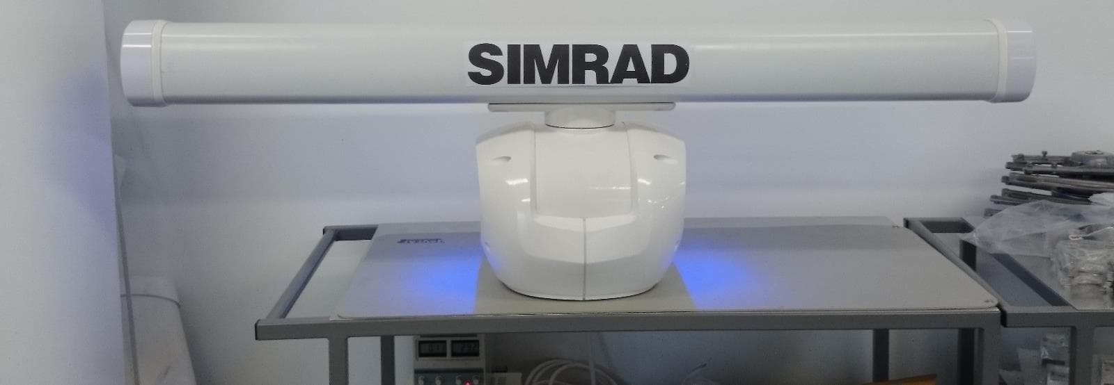
Click to zoom
Application Details
- Equipment Class
- MRD - Marine Radar
- Date of Grant
- Apr 09, 2015
- Application Purpose
- Original Equipment
- Date of Application
- Apr 09, 2015
- Equipment Note
- HALO PULSE COMPRESSION MARINE RADAR
- Frequency Range
- 9400.00000000 - 9495.00000000
- Company
- Navico Inc.
- Country
- United States
Documents & Files
Document Text
Text extracted from the exhibit documents filed with the FCC. Open a document above to read the original.
Users Manual
ENGLISH Halo® Pulse Compression Radar Installation Manual simrad-yachting.com Draft_08_April_2015 Draft_08_April_2015 Preface As Navico is continuously improving this product, we retain the right to make changes to the product at any time which may not be refl ected in this version of the manual. Please contact your nearest distributor if you require any further assistance. It is the owner’s sole responsibility to install and use the instrument and transducers in a manner that will not cause accidents, personal injury or property damage. The user of this product is solely responsible for observing safe boating practices. NAVICO HOLDING AS AND ITS SUBSIDIARIES, BRANCHES AND AFFILIATES DISCLAIM ALL LIABILITY FOR ANY USE OF THIS PRODUCT IN A WAY THAT MAY CAUSE ACCIDENTS, DAMAGE OR THAT MAY VIOLATE THE LAW. Governing Language: This statement, any instruction manuals, user guides and other information relating to the product (Documentation) may be translated to, or has been translated from, another language (Translation). In the event of any confl ict between any Translation of the Documentation, the English language version of the Documentation will be the offi cial version of the Documentation. This manual represents the product as at the time of printing. Navico Holding AS and its subsidiaries, branches and affi liates reserve the right to make changes to specifi cations without notice. Copyright Copyright © 2015 Navico Holding AS. Warranty The warranty card is supplied as a separate document. In case of any queries, refer to the brand web site of your display or system: www.simrad-yachting.com Declarations and conformance This equipment is intended for use in international waters as well as coastal sea areas administered by countries of the E.U. and E.E.A. Compliance Statements The Simrad Halo® pulse compression radar, * Comply with CE under R&TTE directive 1999/5/EC. * The relevant Declaration of Conformity is available in the following website under model documentation section: www.simrad-yachting.com FCC Warning Statement FCC Part 15.19 Warning Statement THIS DEVICE COMPLIES WITH PART 15 OF THE FCC RULES. OPERATION IS SUBJECT TO THE FOLLOWING TWO CONDITIONS: (1) THIS DEVICE MAY NOT CAUSE HARMFUL INTERFERENCE, AND (2) THIS DEVICE MUST ACCEPT ANY INTERFERENCE RECEIVED, INCLUDING INTERFERENCE THAT MAY CAUSE UNDESIRED OPERATION. FCC Part 15.21 Warning Statement NOTE: NAVICO INC. IS NOT RESPONSIBLE FOR ANY CHANGES OR MODIFICATIONS NOT EXPRESSLY APPROVED BY THE PARTY RESPONSIBLE FOR COMPLIANCE. SUCH MODIFICATIONS COULD VOID THE USER’S AUTHORITY TO OPERATE THE EQUIPMENT. FCC Part 15.105(b) Warning Statement NOTE: This equipment has been tested and found to comply with the limits for a Class B digital device, pursuant to part 15 of the FCC Rules. These limits are designed to provide reasonable protection against harmful interference in a residential installation. This equipment generates, uses and can radiate radio frequency energy and, if not installed and used in accordance with the instructions, may cause harmful interference to radio communications. However, there Draft_08_April_2015 is no guarantee that interference will not occur in a particular installation. If this equipment does cause harmful interference to radio or television reception, which can be determined by turning the equipment off and on, the user is encouraged to try to correct the interference by one or more of the following measures: - Reorient or relocate the receiving antenna. - Increase the separation between the equipment and receiver. -Connect the equipment into an outlet on a circuit diff erent from that to which the receiver is connected. -Consult the dealer or an experienced radio/TV technician for help. INDUSTRY CANADA WARNING STATEMENTS: IC RSS-GEN, Sec 7.1.3 Warning Statement ENGLISH: This device complies with Industry Canada license-exempt RSS standard(s). Operation is subject to the following two conditions: (1) this device may not cause interference, and (2) this device must accept any interference, including interference that may cause undesired operation of the device. FRENCH: Le présent appareil est conforme aux CNR d’Industrie Canada applicables aux appareils radio exempts de licence. L’exploitation est autorisée aux deux conditions suivantes : (1) l’appareil ne doit pas produire de brouillage, et (2) l’utilisateur de l’appareil doit accepter tout brouillage radioélectrique subi, même si le brouillage est susceptible d’en compromettre le fonctionnement. IC RSS-GEN, Sec 7.1.2 Warning Statement ENGLISH: Under Industry Canada regulations, this radio transmitter may only operate using an antenna of a type and maximum (or lesser) gain approved for the transmitter by Industry Canada. To reduce potential radio interference to other users, the antenna type and its gain should be so chosen that the equivalent isotropically radiated power (e.i.r.p.) is not more than that necessary for successful communication. FRENCH: Conformément à la réglementation d’Industrie Canada, le présent émetteur radio peut fonctionner avec une antenne d’un type et d’un gain maximal (ou inférieur) approuvé pour l’émetteur par Industrie Canada. Dans le but de réduire les risques de brouillage radioélectrique à l’intention des autres utilisateurs, il faut choisir le type d’antenne et son gain de sorte que la puissance isotrope rayonnée quivalente (p.i.r.e.) ne dépassepas l’intensité nécessaire à l’établissement d’une communication satisfaisante. IC RSS-GEN, Sec 7.1.2 Warning Statement ENGLISH: This radio transmitter – Halo™ Pulse Compression Radar – (4697A-HALO) has been approved by Industry Canada to operate with the antenna types listed below with the maximum permissible gain and required antenna impedance for each antenna type indicated. Antenna types not included in this list, having a gain greater than the maximum gain indicated for that type, are strictly prohibited for use with this device. FRENCH: Le présent émetteur radio – Halo™ …
Text truncated - open the document above for the full version.
Users Manual
| 13 Hardware mounting | Halo pulse compression radar installation manual Surface mount: Rear cable connection 6. Position the scanner carefully over the bolt holes so that they are aligned. 7. Place a fl at washer and spring washer onto each bolt, as shown. 8. Insert bolts into the drilled holes and locate into the pedestals threaded mounting holes and tighten securely. Note: The torque settings for the mounting bolts are XX Nm – XX Nm (8.9 lb ft – 13.3 lb ft) 9. Connect the 14 pin end of the interconnection cable. Take care to align the connector correctly to avoid bending the pins. Secure the locking collar by rotating clockwise until it clicks Draft_08_April_2015 14 | Hardware mounting |Halo pulse compression radar installation manual Pole or tower mount: Discreet cable connection The interconnection cable can be optionally connected discreetly underneath the pedestal by moving the 14 pin connector at the rear of the pedestal to a bracket underneath the pedestal. 1. Remove the retaining nut and pull back the connector and fl y lead. 2. Fit the supplied blanking plug where the connector used to be. Note: The blanking plug is attached the bracket underneath the pedestal. 3. Re-route the internal fl y lead to the bracket and secure with the nut. 4. Connect the interconnection cable. Take care to align the connector correctly to avoid bending the pins. Secure the locking collar by rotating clockwise until it clicks 5. Lower the pedestal carefully over the bolt holes so that they are aligned. 6. Place a fl at washer and spring washer onto each bolt, as shown. 7. Insert bolts into the drilled holes and locate into the pedestals threaded mounting holes and tighten securely. Draft_08_April_2015 | 15 Hardware mounting | Halo pulse compression radar installation manual Fitting the antenna to the pedestal 1. Remove the protective cap from the pedestal and the protective label on the antenna that protects the wave guide. Note: The protection label and waveguide cover is in place to prevent contaminants from entering the waveguide. These covers MUST BE REMOVED IMMEDIATELY PRIOR TO INSTALL- ING THE ANTENNA TO THE PEDESTAL. Note: An antenna Sealing Ring is located under this label in the antenna waveguide chamber. Ensure the Sealing Ring remains in place prior to installing the antenna to the pedestal. 2. Carefully lower the antenna on to the pedestal. The antenna can only fi t one way 3. Place a fl at washer then a spit washer followed by a dome nut on to each of the four antenna studs. Tighten the dome nuts to 15 N·m or (11 lb·ft) Draft_08_April_2015 16 | Wiring |Halo pulse compression radar installation manual Wiring ! Warning: SAFETY SWITCH. The pedestal unit has a safety switch, which removes power from the radar and disables the antenna rotating during maintenance and service. Make sure switch is set to off before commencing installation and back to ON after completion All wiring connections are made inside the RI-12 interface box. It is necessary to remove the lid to gain access to the connections 1. Remove the lid by unscrewing the six retaining screws 2. Remove the grommet retaining clip 3. Remove the rubber grommets 4. Pass the cables through the rubber grommets and into the RI-12. Use a sharp knife to cut a slit the grommet. 5 Draft_08_April_2015 | 17 Wiring | Halo pulse compression radar installation manual RI-12 connections 67 12 3 8910 45 KeyNameDescription 1 FUSE25 Amp blade fuse 2 Power control: REMOTERemote power control activation jumper. Move to REMOTE position so radar power state is controlled by a multifunction display or switch (see “Remote power control” on page 22) 3 Power control: AUTORadar will turn on when power is applied to the main power connector. Remote power wire on AUX IN port is ignored 4 SCANNER POWERPhoenix connector: Provides 36 V DC up to the pedestal and power for the park brake. Connect the four wires of the interconnection cable matching the color coded sticker on the connector 5 NMEA 2000Micro-C: NMEA 2000 network connection 6 SCREENNo connect 7 - SUPPLY+12 or 24 V DC input 8 AUX INPhoenix connector: NMEA 0183 data input, remote power on and DC input for the antenna park brake 9 SCANNERRJ45: Ethernet data from the pedestal. Connect the RJ45 connector of the interconnection cable 10NETWORK/MFDRJ45: Connects the radar to the navigation Ethernet network Draft_08_April_2015 18 | Wiring |Halo pulse compression radar installation manual LED Indicator lights LEDColorIndication PowerGreen steadyPower is applied and the radar is turned on (by either remote power on or power control jumper set to Auto). CommsGreen fl ashingNMEA 2000 traffi c present StatusGreen steadyRadar is transmitting OrangeRadar is in standby RedNo power to the pedestal from the RI-12 Red fl ashingPower supply fault EthernetGreen fast fl ashingEthernet data present Off No connection to any other active Ethernet device Pedestal Interconnection cable The interconnection cable connects the radar pedestal to the RI-12 Interface module. The cable connects to the pedestal using a 14 pin connector. The pedestal 14 pin connector can be set to either rear exit or discrete exit underneath the pedestal. (see “Pole or tower mount: Discreet cable connection” on page 14) Note: Protect the connectors especially the RJ45 connector when pulling cable through the boat and avoid putting strain on to the connectors. The interconnection cable is 9 mm in diameter. A 14 mm hole will be required in order for the RJ45 (Interface module end) to pass through bulkheads or 24 mm hole for the 14 pin connector (pedestal end) to pass though. Run the interconnection cable between the pedestal and the location of the RI-12 Interface module. Draft_08_April_2015 | 19 Wiring | Halo pulse compression radar installation manual Scanner connector Cable connector Diameter = 23 mm Pin- out Wire color 1BlackPedestal power DC (-) 2RedPedestal power DC (+) 3Yellow 4DrainTinned wire 5N/AN/A 6BlueRJ45 Pin 4 7White / BlueRJ45 Pin 5 8Whi…
Text truncated - open the document above for the full version.
Users Manual
| 23 Wiring | Halo pulse compression radar installation manual Network An Ethernet network is used to distribute the radar data to compatible multi-function displays. The RI-12 is connected to the Ethernet network using a standard Simrad Ethernet cable and the supplied adapter cable. The RI-12 can be connected either directly to any Simrad compatible MFD or to a network switch such as an NEP-2 or SonarHub. 1 2 3 4 4 5 6 6 NETWORK /MFD KeyDescription 1 Halo® pulse compression radar pedestal and antenna 2 Multi-function displays 3 RI-12 interface module 4 RJ45 to 5 pin yellow Ethernet adapter (p/n 000-11246-001) 5 NEP-2 or device with a built in Ethernet switch 6Ethernet cables. Supplied with a 1.8 m (6 ft). The RI-12 can connect either directly to a multifunction display or to other an Ethernet switch such as NEP2 or SonarHub Draft_08_April_2015 24 | Wiring |Halo pulse compression radar installation manual NMEA2000 The RI-12 can be connected to a Micro-C NMEA 2000 network to receive heading and position information. A heading sensor is required for the following functionality; • MARPA : heading at 10 Hz or faster is required for the radar to calculate MARPA tracking. Heading must also be connected to the display. • Radar Chart overlay: heading is required by the display to correctly overlay the radar over a chart. • North Up: For the display to show the radar page with the top of the PPI as north. For heading sensors that output NMEA 0183 (see “NMEA 0183” on page 25) For magnetic heading sensors, heading calibration should be performed before using MARPA or Chart Overlay, and repeated annually, and after any major structural changes to the vessel. + _ 12 V DC T T 2 6 7 5 43 5 1 KeyDescription 1 Halo® radar pedestal and antenna 2 RI-12 interface modules 3 NMEA 2000 compliant heading sensor 4 Compatible multifunction display 5 Micro-C drop cables 6Network power 12 V DC 7Micro-C backbone (NMEA 2000) with terminators Draft_08_April_2015 | 25 Wiring | Halo pulse compression radar installation manual NMEA 0183 The RI-12 has one NMEA 0183 (RS422) to accept heading and position information. The NMEA 0183 port accepts data at 4,800 baud. Sentences used HDG, HDT, HDM, GGA, GLL, RMC, VTG. Heading should be at a minium of 10 Hz update rate. NMEA 0183 RX_A NMEA 0183 RX_B RI-12 heading source selection: The RI-12 receives heading via the NMEA 2000 network and transmits this data to the radar, where MARPA processing is performed. For Simrad installations with more than one heading source the RI-12 will use the Simrad group source. The source used by the Simrad group can be viewed or changed via the multifunction display in the Settings>Network>Sources... menu. Note: If an NMEA 0183 heading source is connected the RI-12 will use this. It will ignore a NMEA 2000 heading source. Antenna park The Halo® Pulse Compression Radar has the ability to stop rotating the antenna and hold it at a predetermined angle in relation to the ships heading line. The park angle is set in the display (see “Adjust open array park angle” on page 28). In conjunction with this setting there is a park angle retention feature which is a very low current electromagnet that will provide resistance for the antenna to maintain a parked angle against wind and movement. The park brake requires a continuous low current DC supply (10-32 V DC). This draws less than 100uA. + _ 12 -24 V DC Draft_08_April_2015 26 | Setup and confi guration |Halo pulse compression radar installation manual When all connections have been made and checked the safety switch on the rear of the pedestal can be set to the ON position Setup and confi guration Setup and confi guration of the Halo® radar has been simplifi ed compared to traditional pulse radars. There is no zero range adjustment (time delay), no warm up time, and no burn in required. Source On the radar page, choose the radar to be setup using the source drop down. MENU>SOURCE When setting up the Halo Pulse Compression radar choose either Halo-A or Halo-B is selected Note: following settings require the radar to be in Transmit mode. MENU>TRANSMIT Entering radar setup on your display Enter radar installation by pressing MENU > SETTINGS > RADAR > INSTALLATION. Select the antenna length Select the correct length of antenna. Select Save to exit back to the radar installation page. 6 Draft_08_April_2015 | 27 Setup and confi guration | Halo pulse compression radar installation manual Adjust antenna height... Set the radar scanner height. Use the slider control or the “+” or “-” buttons to set the value then SAVE. Note: It is very important to set the antenna height confi gured correctly as this will aff ect the sea clutter function. Do not set the height to 0. Adjust bearing alignment... Adjust the heading marker. This is to align with the heading marker on the screen with the center line of the vessel, this will compensate for any slight misalignment of the pedestal during installation. Any inaccuracy will be evident when using MARPA or chart overlay. Point the boat to the end of a head land or peninsula. Adjust the bearing alignment so the heading line touches the end of the same head land or peninsula. Use the slider control or the “+” or “-” buttons to set the value then SAVE Draft_08_April_2015 28 | Setup and confi guration |Halo pulse compression radar installation manual Sector blanking On vessels where the radar is installed in close proximity to a mast or structure that could cause unwanted refl ections or interference to appear on the radar image. Use the sector blanking feature to stop the radar from transmitting in the direction up to four sectors. Note: Sectors are setup relative to the heading line of the radar. The bearing of the sector is measured from the front of the vessel to the center line of the sector. Adjust open array park angle The park angle is the fi nal resting position of the antenna relative to the heading line of the radar when the radar is set to standby. The antenna will s…
Text truncated - open the document above for the full version.
Users Manual
| 35 Drawings | Halo pulse compression radar installation manual Antenna maximum rotation 1141 mm (44.92") 1431 mm (56.77") 2045 mm (80.51") 6 ft 4 ft 3 ft Draft_08_April_2015 36 | Spare Parts |Halo pulse compression radar installation manual Spare Parts Part NumberDescription 000-11463-001Halo pedestal 000-11464-0013 ft (1127 mm) antenna 000-11465-0014 ft (1431 mm) antenna 000-11466-0016 ft (2038 mm) antenna 000-11467-001RI-12 Radar interface module AA010211Broadband scanner interconnection cable 10 m (33 ft) AA010212Broadband scanner interconnection cable 20 m (65.6 ft) AA010213Broadband scanner interconnection cable 30 m (98.5 ft) 000-11246-001Adapter cable: yellow Ethernet female to RJ45 male. 150 mm (5.9”) 000-11246-001 Adapter cable: yellow Ethernet female to RJ45 male150 mm (5.9”) 000-00127-28Ethernet cable0.6 m (2 ft) 000-0127-51Ethernet cable1.8 m (6 ft) 000-0127-29Ethernet cable4.5 m (15 ft) 000-0127-30Ethernet cable7.7 m (25 ft) 000-0127-37Ethernet cable15.2 m (50 ft) 24005936AT10 NMEA0183 / NMEA 2000 converter (SimNet connector) 24006694AT10HD NMEA0183 / NMEA 2000 (SimNet connector) converter. 10 Hz heading data only 9 Draft_08_April_2015 | 37 Spare Parts | Halo pulse compression radar installation manual Service parts Part NumberDescription 151-10439-001Pedestal case LEFT with LED assembly. 151-10438-001Pedestal case RIGHT with LED assembly. 151-10446-001Pedestal case seal kit 151-10435-001Motor assembly type 1 151-10436-001Motor assembly type 2 151-10437-001Gear assembly 151-10442-001LED Replacement kit: LED PCB, Light guide and seal. 151-10443-001Replacement RF Transceiver unit Motor Capacitor 151-10444-001Pedestal cable kit Draft_08_April_2015 38 | Spare Parts |Halo pulse compression radar installation manual 151-10447-001Antenna end caps 151-10448-001Pedestal mounting kit 151-10449-001Antenna mounting kit 151-10440-001CPU PCB assembly 151-10441-001PSU PCB assembly Draft_08_April_2015 | 39 Spare Parts | Halo pulse compression radar installation manual Third party mounting options Seaview ImageManufacturers part no.Description PMF-57-M1127 mm (5.7”) tall forward leaning mount PMA-57-M1127 mm (5.7”) tall aft leaning mount ADA-R1Top plate ADA-HALO-3Adapter plate. Used in conjunction with ADA-R1 and a mounting tower RW4-74° Angled wedge adapter ADA-HALO-2Adapter for replacing 3G/4G, Raymarine and Garmin radars with Halo PMA-DM2-M2Dual mount. (Not for 6 ft Halo) Scanstrut Edson Draft_08_April_2015 40 | Trouble shooting |Halo pulse compression radar installation manual Trouble shooting Find out software version information On the MFD go to Settings>Radar settings>Installation>Radar status No Radar. No Ethernet network connection has been established between the MFD and the pedestal . Check the following Power: Radar not powered on. • Check the safety switch on the rear of the pedestal is on • Check the power LED on the RI-12 is steady green. • Check if using remote power control (see “Remote power control” on page 22). • Check output voltage of RI-12 upto the pedestal should be 36 Volts No Ethernet LED on RI-12, • Check device that it is connected to is on .e.g check NEP-2 • Bad ethernet cable • Check for RJ45 connection and Ethernet adapter cable • Check RJ-45 connector on interconnection cable, check for bent tarnished or corroded pins on RJ-45 connector. No Comms L.E.D on the RI-12. (No communication with the pedestal) • Check NMEA2000 • Device list • Check N2k Diagnostics page for bus status Software: • Check the MFD and radar have up to date software. Refer to the www.simrad-yachting. com website for more information • Check the Radar source is set correctly Incompatible MFD type. • NSS evo2 / NSO evo2 or later No Spoke data No Scanner No PPI image No error message is displayed but there is no radar image on the screen. Possible hardware fault in the rotating antenna module. Possibly a transmitter or receiver fault. If transmitter failure then when the MFD gain control is increased there will be noise on the screen. If receiver failure, there will be no noise on the screen when the MFD gain control is increased. Poor performance • Check antenna length (see “Select the antenna length” on page 26) • Check antenna height (see “Adjust antenna height...” on page 27) • Check Sidelobe suppression (see “Sidelobe suppression...” on page 28) Error codes 10 Draft_08_April_2015 | 41 Trouble shooting | Halo pulse compression radar installation manual Power cycle to reset Draft_08_April_2015 42 | Trouble shooting |Halo pulse compression radar installation manual Draft_08_April_2015 *988-10676-001* 0560 www.simrad-yachting.com Draft_08_April_2015
External Photos
Confidential Navico 2014, 2015 Page 1 of 4 Halo® Pulse Compression Radar Internal Pictures – RF Module – Brick:
ID Label/Location Info
Halo™ Pulse Compression Radar Commercial-In-Confidence Halo™ Radar – Serial number locations HALO Pedestal: 000-11463-001 PEDESTAL, RADAR, HALO HALO Pedestal – FRONT View HALO Pedestal – REAR View Halo™ Pulse Compression Radar Commercial-In-Confidence HALO Pedestal – Serial number label location HALO Pedestal – Serial number label Halo™ Pulse Compression Radar Commercial-In-Confidence HALO Antennas: 000-11464-001 ANTENNA, 3ft, HALO 000-11465-001 ANTENNA, 4ft, HALO 000-11466-001 ANTENNA, 6ft, HALO HALO Antenna – FRONT View HALO Antenna – REAR View Halo™ Pulse Compression Radar Commercial-In-Confidence HALO Antenna – REAR View HALO Antenna – Serial Number label location Antenna – Serial Number label – 3ft Antenna – Serial Number label – 4ft Antenna – Serial Number label – 6ft
Internal Photos
Confidential Navico 2014, 2015 Page 1 of 4 Halo® Pulse Compression Radar Internal Pictures – RF Module – Brick: Confidential Navico 2014, 2015 Page 2 of 4 TX Module: RX Module: Confidential Navico 2014, 2015 Page 3 of 4 Confidential Navico 2014, 2015 Page 4 of 4 Halo™ Pulse Compression Radar Commercial-In-Confidence Confidential Navico 2014, 2015 Page 5 of 12 PCBA Pictures: HALO CPU PCBA Halo™ Pulse Compression Radar Commercial-In-Confidence Confidential Navico 2014, 2015 Page 6 of 12 HALO PSU PCBA Halo™ Pulse Compression Radar Commercial-In-Confidence Confidential Navico 2014, 2015 Page 7 of 12 HALO REF PCBA Halo™ Pulse Compression Radar Commercial-In-Confidence Confidential Navico 2014, 2015 Page 8 of 12 HALO TX PCBA Halo™ Pulse Compression Radar Commercial-In-Confidence Confidential Navico 2014, 2015 Page 9 of 12 HALO RX PCBA Halo™ Pulse Compression Radar Commercial-In-Confidence Confidential Navico 2014, 2015 Page 10 of 12 HALO PA PCBA Halo™ Pulse Compression Radar Commercial-In-Confidence Confidential Navico 2014, 2015 Page 11 of 12 HALO AZIMUTH PCBA Halo™ Pulse Compression Radar Commercial-In-Confidence Confidential Navico 2014, 2015 Page 12 of 12 HALO LED PCBA – LEFT & RIGHT (LEFT SHOWN)
RF Exposure Info
RF Exposure Evaluation Report APPLICANT NAVICO AUCKLAND LTD 44 ARRENWAY DRIVE, ROSEDALE P.O. Box 331146 TAKAPUNA, AUCKLAND 0632 New Zealand FCC ID RAYHALO MODEL NUMBER HALO PRODUCT DESCRIPTION MARINE PULSE COMPRESSION RADAR STANDARD APPLIED CFR 47 Part 2.1091 PREPARED BY Sid Sanders We, TIMCO ENGINEERING, INC. would like to declare that the device has been evaluated in accordance with 47 CFR Part 2.1091 and meets the requirements. The attached report shall not be reproduced except in full without the written approval of TIMCO ENGINEERING, INC. 849 NW STATE ROAD 45 NEWBERRY, FL 32669 USA PH: 888.472.2424 OR 352.472.5500 FAX: 352.472.2030 EMAIL: [email protected] HTTP://WWW.TIMCOENGR.COM Applicant: NAVICO AUCKLAND LTD FCC ID: RAYHALO Report: N\ NAVICO AUCKLAND_RAY\268ZAUT15\268ZAUT15TestReport.docxt Page 2 of 4 GENERAL REMARKS Attestations This equipment has been evaluated in accordance with the standards identified in this report. To the best of my knowledge and belief, these evaluations were performed using the procedures described in this report. I attest that the necessary evaluations were made, under my supervision, at: Timco Engineering Inc. 849 NW State Road 45 Newberry, Fl 32669 Authorized Signatory Name: Sid Sanders Engineering Project Manager Date: 4/7/2015 RF Exposure Requirements General information Device type: MARINE PULSE COMPRESSION RADAR Devices that operate under Part 80, 90 of this chapter are subject to RF exposure evaluation prior to equipment authorization or use. Antenna Configuration Antenna p/n Type Max. Gain (dBi) 6 ft. Halo 000-11466-001 Halo 29 dBi Operating configuration and exposure conditions: The conducted output power is shown in the table below. Typical use qualifies for a maximum duty cycle factor of 100%. Operation: A typical installation consists of an antenna system with a 10 meter coaxial cable of the type RG 213/ U type which has a loss as follows; Nom. Attenuation for RG 213/U: Frequency MHz Attenuation per 100ft. dB 1 .27 10 .55 50 1.3 100 1.9 200 2.7 400 4.1 700 6.5 900 7.6 1000 8.0 4000 21.5 MPE Calculation: The minimum separation distance is calculated as follows: Applicant: NAVICO AUCKLAND LTD FCC ID: RAYHALO Report: N\ NAVICO AUCKLAND_RAY\268ZAUT15\268ZAUT15TestReport.docx The limit for general uncontrolled exposure environment is shown in FCC rule Part 1.11310, Table 1. Max Power 1 W equalsMax Power 1000mW Duty Cycle10 %equalsDuty Factor0.1numeric Antenna Gain 29dBiequalsGain numeric794.3282numeric Coax Loss0 dB Gain - Coax Loss794.3282numeric Power Density 1 mW/cm 2 Frequency9495MHzFrequency rangPower denEnter this value MHz mW/cm 2 mW/cm 2 0.3-1.34100100 1.34-30 180/f 2 0.0 30-3000.20.2 300-1,500f/15006.3 1,500-100,00011 f = frequency in MHz Minimum Separation Distance 80 cm0.80 m Minimum Seperation in Inches31.27731Inches Minimum Separation Distance for Mobile or Fixed Devices General Population/Uncontrolled Exposure Insert values in yellow highlighted boxes to determine Minimum Separation Distance Enter power Density from the chart to the rightRule Part 1.1310, Table 1
Test Report
FCC PART 80, 90 RADAR TEST REPORT APPLICANT NAVICO AUCKLAND LTD 44 ARRENWAY DRIVE, ROSEDALE P.O. Box 331146 TAKAPUNA, AUCKLAND 0632 New Zealand FCC ID RAYHALO MODEL NUMBER HALO PRODUCT DESCRIPTION MARINE PULSE COMPRESSION RADAR DATE SAMPLE RECEIVED 4/6/2015 DATE TESTED 4/7/2015 TESTED BY Christian Pawlak APPROVED BY Sid Sanders TEST RESULTS PASS FAIL Report Number Version Number Description Issue Date 268YAUT15TestReport.docx Rev.1 Initial Issue 4/7/2015 Rev. 1.5 Corrected Typo on Freq. Stab. Test 4/16/15 THE ATTACHED REPORT SHALL NOT BE REPRODUCED EXCEPT IN FULL WITHOUT THE WRITTEN APPROVAL OF TIMCO ENGINEERING, INC. 849 NW STATE ROAD 45 NEWBERRY, FL 32669 USA PH: 888.472.2424 OR 352.472.5500 FAX: 352.472.2030 EMAIL: [email protected] HTTP://WWW.TIMCOENGR.COM Applicant: NAVICO AUCKLAND LTD FCC ID: RAYHALO Report: N\ NAVICO AUCKLAND_RAY\268YAUT15\268YAUT15TestReport.docx Page 2 of 27 TABLE OF CONTENTS GENERAL REMARKS.................................................................................................. 3 EUT SPECIFICATION ................................................................................................. 4 TEST SETUP INFORMATION ....................................................................................... 4 TEST REPORT SUMMARY ........................................................................................... 5 RF POWER OUTPUT .................................................................................................. 6 MODULATION CHARACTERISTICS .............................................................................. 7 MODULATION CHARACTERISTICS(Cont.) ..................................................................... 8 MODULATION CHARACTERISTICS(Cont.) ..................................................................... 9 MODULATION CHARACTERISTICS(Cont.) ................................................................... 10 MODULATION CHARACTERISTICS(Cont.) ................................................................... 11 MODULATION CHARACTERISTICS(Cont.) ................................................................... 12 MODULATION CHARACTERISTICS(Cont.) ...............…
Text truncated - open the document above for the full version.
Contact Information
Applicant
Filippo Campolmi(Regulatory Compliance Manager)
Technical Contact
Timco Engineering, Inc.Christian Pawlak
[email protected]888-472-2424
849 NW State Road 45 · Newberry · United States
Non-Technical Contact
Timco Engineering, Inc.Sharon Hoffman
[email protected]888-472-2424
Test Firm
Timco Engineering, Inc.Bruno Clavier
Technical Specifications
| # | Rule Parts | Frequency Range | Power Output | Emission | Tolerance |
|---|---|---|---|---|---|
| 1 | 80,90 | 9.40 GHz - 9.49 GHz | 25 W | 106MP0N | 106.2700000000 ppm |
Other Applications from Navico Inc.

RAYVHFNRS2A
Aug 11, 2021MARINE BLACK BOX DSC/AIS VHF RADIO SYSTEM
Equipment Class
DTS - Digital Transmission System
RAYVHFNRS1A
May 18, 2021MARINE BLACK BOX DSC/AIS VHF RADIO SYSTEM
Equipment Class
DTS - Digital Transmission System
RAYVHFNRS2
Nov 30, 2020MARINE BLACK BOX DSC/AIS VHF RADIO SYSTEM
Equipment Class
JAB - Part 15 Class B Digital Device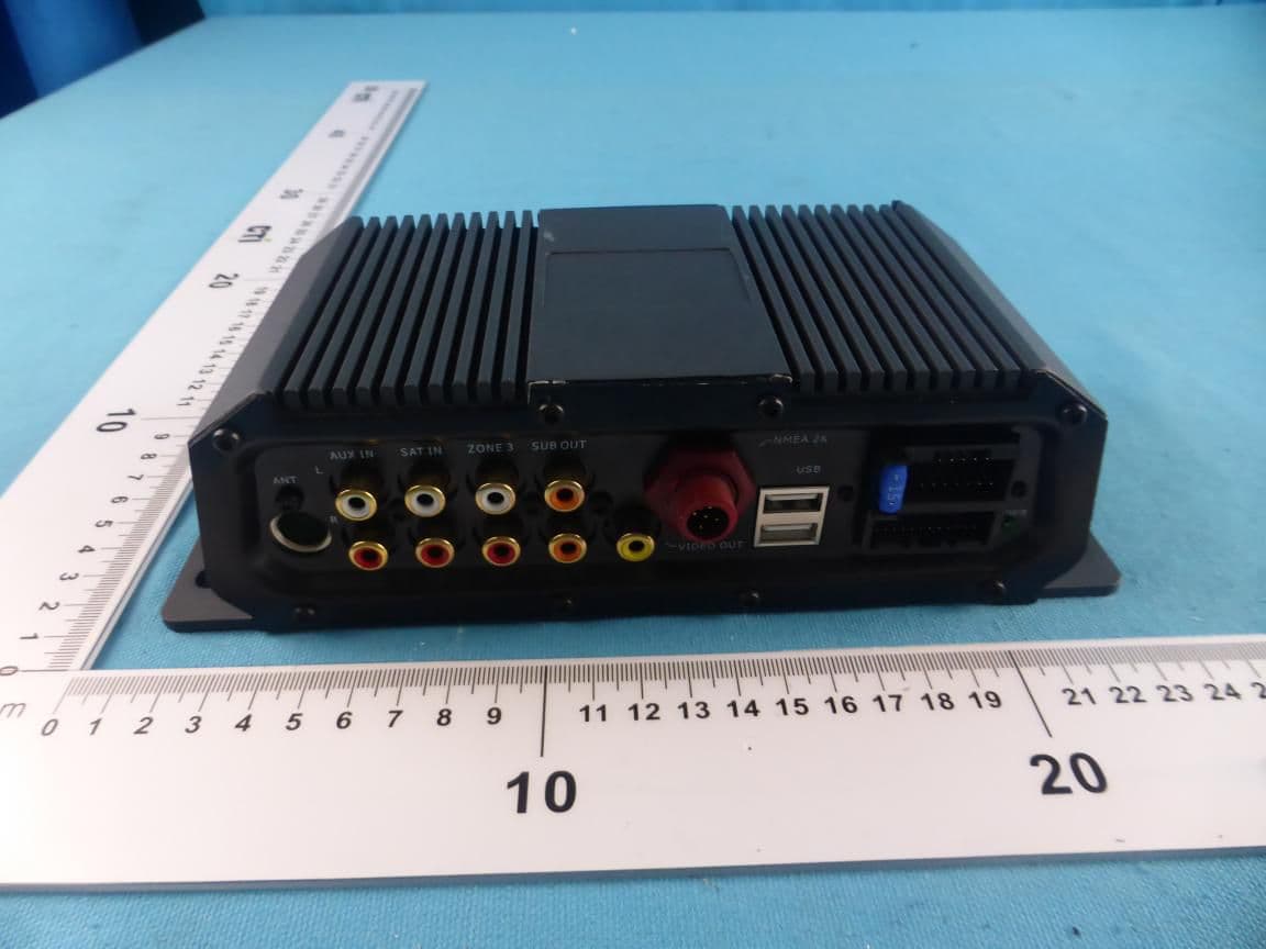
RAYSHGEN2
Sep 17, 2015Marine Entertainment System
Equipment Class
DTS - Digital Transmission System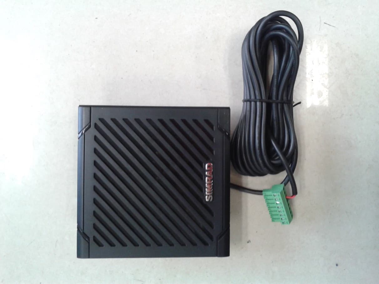
RAYVHFRS90
Mar 05, 2014BASE STATION VHF RADIO
Equipment Class
TNB - Licensed Non-Broadcast Station Transmitter