RAYVHFRS90BASE STATION VHF RADIO
Navico Inc.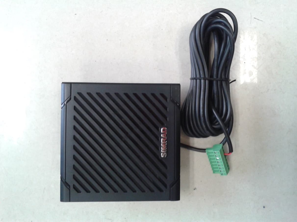
Click to zoom
Application Details
- Equipment Class
- TNB - Licensed Non-Broadcast Station Transmitter
- Date of Grant
- Mar 05, 2014
- Application Purpose
- Original Equipment
- Date of Application
- Mar 05, 2014
- Equipment Note
- BASE STATION VHF RADIO
- Frequency Range
- 156.02500000 - 157.42500000
- Company
- Navico Inc.
- Country
- United States
Documents & Files
Document Text
Text extracted from the exhibit documents filed with the FCC. Open a document above to read the original.
Users Manual
ENGLISH RS90 Operating Manual www.simrad-yachting.com Draft v5.0 27 Feb 2014 Draft v5.0 27 Feb 2014 | 3 RS90 Operating Manual Preface Copyright © 2014 Navico. All rights reserved. Simrad® is a registered trademark of Navico No part of this manual may be copied, reproduced, republished, transmitted or distributed for any purpose, without prior written consent of Simrad Electronics. Any unauthorized commercial distribution of this manual is strictly prohibited. Simrad Electronics may find it necessary to change or end our policies, regulations, and special offers at any time. We reserve the right to do so without notice. All features and specifications subject to change without notice. All screens in this manual are simulated. For free owner’s manuals and the most current information on this product, its operation and accessories, visit our web site: www.simrad-yachting.com Navico Holding AS is not responsible for any changes or modifications to the radio not expressly approved by Navico AS as the responsible entity for its compliance. Modifications could void the user’s authority to operate the radio. Compliance statements DISCLAIMER: It is the owner’s sole responsibility to install and use the instrument and transducers in a manner that will not cause accidents, personal injury or property damage. The user of this product is solely responsible for observing safe boating practices. NAVICO HOLDING AS. AND ITS SUBSIDIARIES, BRANCHES AND AFFILIATES DISCLAIM ALL LIABILITY FOR ANY USE OF THIS PRODUCT IN A WAY THAT MAY CAUSE ACCIDENTS, DAMAGE OR THAT MAY VIOLATE THE LAW. Governing Language: This statement, any instruction manuals, user guides and other information relating to the product (Documentation) may be translated to, or has been translated from, another language (Translation). In the event of any conflict between any Translation of the Documentation, the English language version of the Documentation will be the official version of the Documentation. This manual represents the RS90 as at the time of printing. Navico Holding AS. and its subsidiaries, branches and affiliates reserve the right to make changes to specifications without notice. Draft v5.0 27 Feb 2014 4 | RS90 Operating Manual IMPORTANT 1. DS C functions will not operate on the RS90 until your MMSI has been entered. 2. The radio channels installed into this Simrad VHF radio may vary from country to country depending upon the model and government or national communications authority regulations. 3. Na vico recommends that you check the radio operating licensing requirements of your country before using this Simrad VHF radio. The operator is solely responsible for observing proper radio installation and usage practices. 4. A DS C warning label is supplied with this Simrad VHF radio. To comply with FCC regulations, this label must be affixed in a location that is clearly visible from the operating controls of this radio. Make sure that the chosen location is clean and dry before applying this label. 5. This radio is designed to generate a digital maritime distress call to facilitate search and rescue. To be effective as a safety device, this radio must be used only within the geographic range of a shore- based VHF marine Channel 70 distress and safety watch system. The geographic range may vary but under normal conditions is approximately 20 nautical miles. MMSI and license information You must obtain a user MMSI (Maritime Mobile Service Identity) and enter it into your RS90 radio in order to use the DSC functions. Contact the appropriate authorities in your country. If you are unsure who to contact, consult your Simrad dealer. The user MMSI is a unique nine digit number, similar to a personal telephone number. It is used on marine transceivers that are capable of using DSC (Digital Select Calling). Depending upon your location, you may need a radio station license for the RS90 You may also need an individual operator’s license. Simrad recommends that you check the requirements of your national radio communications authorities before operating DSC functions. Draft v5.0 27 Feb 2014 | 5 RS90 Operating Manual RF emissions notice This equipment complies with FCC radiation exposure limits set forth for an uncontrolled environment. This device’s antenna must be installed in accordance with provided instructions; and it must be operated with minimum 96 cm spacing between the antennas and all person’s body (excluding extremities of hands, wrist and feet) during operation. Further, this transmitter must not be co-located or operated in conjunction with any other antenna or transmitter. FCC statement This device complies with Part 15 of the FCC Rules. Operation is subject to the following two conditions: (1) this device may not cause harmful interference, and (2) this device must accept any interference received, including interference that may cause undesired operation. ¼No te: This equipment has been tested and found to comply with the limits for a Class B digital device, pursuant to Part 15 of the FCC Rules. These limits are designed to provide reasonable protection against harmful interference in a normal installation. This equipment generates, uses and can radiate radio frequency energy and, if not installed and used in accordance with the instructions, may cause harmful interference to radio communications. However, there is no guarantee that interference will not occur in a particular installation. If this equipment does cause harmful interference to radio or television reception, which can be determined by turning the equipment off and on, the user is encouraged to try to correct the interference by one or more of the following measures: • Reorient or relocate the receiving antenna. • Increase the separation between the equipment and receiver. • Connect the equipment into an output on a circuit different from that to which the receiver is connected. • Con sult the dealer or an experienced technician for help. • A sh ielded cable mu…
Text truncated - open the document above for the full version.
Users Manual
| 65 DSC Procedures | RS90 Operating Manual ATIS EU models only. The Automatic Transmitter Identification System (ATIS) is mandatory for vessels navigating on some European waterways. The system allows authorities to monitor and regulate VHF radio communications by identifying any vessel that makes a VHF transmission. Each vessel is required to have an ATIS-enabled radio on board and is allocated a unique ATIS Maritime Mobile Service Identity (MMSI). Each time a radio operator finishes talking and releases the PTT key, the radio transmits a short digital message, which includes the ATIS MMSI. The receiving station can then look up details of the vessel, saving time in communication on the busy VHF channels. Unlike DSC, the ATIS signal is transmitted on the same VHF channel as the voice transmission. Before you can enable ATIS, you must enter the ATIS MMSI. See “Entering or checking your ATIS MMSI” on page 83. Before you can enable ATIS, DSC must be turned off. See ”Enabling DSC functionality” on page 84. To enable ATIS, see “Enabling ATIS functionality” on page 83. ¼Notes • ATIS is disabled in US models. • When ATIS is enabled, the ATIS icon appears on screen. • In some European countries SCAN functionality is limited, and, if ATIS is enabled, the 3CH SCAN and Dual scan modes will be disabled. Draft v5.0 27 Feb 2014 66 | AIS procedures | RS90 Operating Manual AIS procedures The marine Automatic Identification System (AIS) is a vessel location and information reporting system. It allows vessels to automatically share information such as position, speed, course and identity via a VHF radio link. The received details of nearby vessels can be displayed on the handset screen together with closest point of approach times and distances. These details are also sent to the NMEA ports for display on a chart plotter if one is connected. Closest point of approach (CPA) is the calculated closest distance between your vessel and a target vessel based on the current speed and course. Time to closest point of approach (T/CPA) is the calculated time for a target vessel to arrive at the closest point of approach based on the current speed and course. If the radio detects that another vessel will come closer than the set CPA distance and within the set T/CPA time, the CPA alarm will sound. Both conditions must be met for the CPA alarm to sound. For information on enabling AIS and setting the CPA time and distance criteria, see “AIS Setup” on page 88. For general information about AIS, see “Appendix 9 - AIS information” on page 105. For information on how to configure your chart plotter or software to make use of the RS90 AIS data, see the manual provided with that product. ¼No tes • Before the AIS functions can be used, the RS90 must receive its own position from a GPS device, or manually entered data. • The RS90 VHF radio includes an AIS receiver but does not transmit. To access the AIS displays: • Press [AIS] • Repeat press [AIS] to switch between the three available displays: MMSI list (list of nearby vessels) PPI display T/CPA lis t From any of the above displays, you can select an MMSI to display details about the particular vessel. 7 Draft v5.0 27 Feb 2014 | 67 AIS procedures | RS90 Operating Manual List of nearby vessels The MMSI list displays a list of vessels within VHF range. The list is arranged in ascending order; closest first. Each vessel’s MMSI (or name, depending on AIS setup) will be displayed, together with its bearing and distance from your position. PPI display The Plan Position Indicator (PPI) shows the geographical location of AIS targets with respect to your position, which is represented in the centre of the circular display. Symbols • The solid circle in the middle is your vessel. • Hollow diamonds represent vessels that are within he current zoom distance. • The solid diamond is the selected target vessel. • The tails represent course over ground. ¼No te: Units on the PPI display are always nautical miles. 1SEASPRAY 2250.59nM 2SUNBIRD 2751.43nM 8n MMMSI LIST 1/2 AIS CHART1/98 Draft v5.0 27 Feb 2014 68 | AIS procedures | RS90 Operating Manual To zoom in or out: • Press [3CH] to zoom in. • Press [Scan] to zoom out. Scales available are 1nm / 2 nm / 4 nm / 8 nm / 16 nm / 32 nm. T/CPA screen The Time and Closest Point of Approach (T/CPA) screen shows the closest point of approach settings together with a list of vessels that will approach within those criteria. • CPA alert distance is set up in MENU → AIS SETUP → CPA. (See “Setting up the CPA distance” on page 89.) • T/CPA alert time is set up in MENU → AIS SETUP → TCPA. (See “Setting up the T/CPA time” on page 90.) The approaching AIS target’s details will be listed on the left of the screen. Once the vessel is within alert distance (CPA) or time (T/CPA), it will be placed in the T/CPA list. The alert sounds for every vessel within the criteria every time their AIS signal is received. T/CPA APPR OACH 1/ 9 05:00min 8 nM • In t he example above, the criteria are: 5:00min and 8nM. ¼No tes: • The scale on the T/CPA Approach screen is automatically set to the optimum for the selected target. You cannot zoom in or out on this screen. • If the radio detects a T/CPA or CPA breach, the T/CPA Approach screen will automatically popup with an alert tone. Press [X] to stop the alert; otherwise, the alert will sound again after 1 minute. Draft v5.0 27 Feb 2014 | 69 AIS procedures | RS90 Operating Manual AIS Target information From one of the AIS screens, you can display detailed information about a target vessel: 1. Pre ss ▲ or ▼ to highlight the required target. (Hold down ▲ or ▼ to scroll rapidly.) 2. Pr ess [OK] to view full details of the selected target, including: • NAME: MMSI: TCPA: 4:39s CPA: 0.59nM WIDTH: 26.0m LENGTH: 158.0m RECEIVED: 0m33s CALL SIGN: MYHV6 D R AU G H T: D IS T: 1. 01n M IMO: B E A R : 155’ HEADING: R O T: 7 2 5 . 6’/m i n SOG: 0.0KTS COG: 0.0’ 55’51.240’N, 012’49.991’E TYPE: CARGO NAV STATUS: NOT DEFINED The display alt…
Text truncated - open the document above for the full version.
Users Manual
| 91 Setup | RS90 Operating Manual GPS setup If a GPS receiver is connected to the NMEA port of the RS90, the radio will automatically receive the vessel’s position and local time from the GPS. If GPS data is not available for some reason, the radio will sound the NO GPS alert for 2 minutes (or until you press any key). If the GPS data becomes older than 4 hours, the NO GPS alert will sound, and it can only be silenced manually or by the reception or manual entry of new GPS data. If the vessel’s GPS data is older than 23.5 hours, the data will be erased and the NO GPS alert will sound. Manually entering position and UTC time ¼Note: this function is only shown when there is no GPS receiver connected. 1. Se lect MENU → G PS / DATA → MANUAL. 2. En ter the latitude, then the longitude, then the UTC. When you have finished, the latitude, longitude and UTC time will be shown on the standby screen. The prefix M indicates a manual entry. ¼Notes • Manual entries are cancelled if a real GPS position is received. • A warning will be displayed after 4 hours to remind you that the current position information was manually entered. DSC MENUSELECT BUDDYLIST LOCAL/DIST CONTRAST GPS/DATA USA 16 Hi DSC PRI GPS/DATA MANUAL SETTING GPSSOURCE USA 16 Hi DSC PRI USA A RESTRICTED 12:28LOC M2756.020 N 08250.190 W 16 Hi DSC PRI Draft v5.0 27 Feb 2014 92 | Setup | RS90 Operating Manual Setting up local time offset If your position and time data are being updated through a GPS receiver, you can enter the time difference between UTC and local time. Then the local time will be displayed on the screen. 1. Se lect MENU → G PS / DATA → SET TING → TIME OFFSET 2. En ter the difference between UTC and local time. You can set in quarter-hour increments up to a maximum offset of ±13 hours. ¼No te: When local time is being displayed, LOC is displayed after the time on the standby screen. Time format options Time can be shown in 12 or 24 hour format. 1. Se lect MENU → G PS / DATA → SET TING → TIME FORMAT. 2. Select 12- or 24-hour as required. ¼Note: When the 12-hour format has been selected, the time is displayed with an AM or PM suffix. Time display options You can toggle on or off the time display on the handset screens. 3. Select MENU → G PS / DATA → SET TING → TIME DISPLY. 4. Se lect ON or OFF as required. DSC MENUSELECT BUDDYLIST LOCAL/DIST CONTRAST GPS/DATA USA 16 Hi DSC PRI GPS/DATA MANUAL SETTING GPSSOURCE USA 16 Hi DSC PRI SETTING TIMEOFFSET TIMEFORMAT TIMEDISPLY LLDISPLY USA 16 Hi DSC PRI GPS/DATA MANUAL SETTING GPSSOURCE USA 16 Hi DSC PRI SETTING TIMEOFFSET TIMEFORMAT TIMEDISPLY LLDISPLY USA 16 Hi DSC PRI GPS/DATA MANUAL SETTING GPSSOURCE USA 16 Hi DSC PRI SETTING TIMEOFFSET TIMEFORMAT TIMEDISPLY LLDISPLY USA 16 Hi DSC PRI Draft v5.0 27 Feb 2014 | 93 Setup | RS90 Operating Manual Position display options You can display or hide your vessel’s position on screen. 1. Select MENU → G PS / DATA → SET TING → LL DISPLY. 2. Select ON or OFF as required. Course and speed display options If position and time are being updated through a GPS navigation receiver, you can display or hide your course over ground (COG) and speed over ground (SOG) data on screen. 1. Select MENU → G PS / DATA → SET TING → COG/SOG. 2. Select ON or OFF as required. GPS alert options If the GPS Alert setting is ON and no GPS signal is received for a period of 10 minutes, the alarm will sound for 2 minutes. 1. Select MENU → G PS / DATA → SET TING → GPS ALERT. 2. Select ON or OFF as required. ¼No te: The default setting is ON for the RS90 EU and OFF for the RS90 US. GPS/DATA MANUAL SETTING GPSSOURCE USA 16 Hi DSC PRI SETTING TIMEOFFSET TIMEFORMAT TIMEDISPLY LLDISPLY Lo USA 16 Hi DSC PRI GPS/DATA MANUAL SETTING GPSSOURCE USA 16 Hi DSC PRI SETTING COG/SOG TIMEFORMAT TIMEDISPLY LLDISPLY Lo USA 16 Hi DSC PRI GPS/DATA MANUAL SETTING GPSSOURCE USA 16 Hi DSC PRI SETTING COG/SOG GPS ALERT TIMEDISPLY L LDISPLY Lo USA 16 Hi DSC PRI Draft v5.0 27 Feb 2014 94 | Setup | RS90 Operating Manual General setup Radio sensitivity LOCAL/DIST allows you to set the sensitivity of the radio as follows: • LOCAL Recommended for use in areas of high radio noise; for example, close to cities. It is not recommended for open sea conditions. Local is displayed on the handset screen. • D IS TA N T Recommended for open sea conditions. 1. Select MENU → LO C AL /DIS T. 2. Scroll to DISTANT or LOCAL as required. 3. Pr ess [OK]. ¼Note: See also “Adjusting squelch” on page 24. Display contrast level Select MENU → CONTRAST. 1. Use the ▲ or ▼ keys to raise or lower the contrast. 2. Press [OK] to accept the setting. GPS simulator The GPS simulator creates GPS data for test purposes. 1. Select MENU → GPS SIM. 2. Select ON or OFF as required. ¼Notes • The GPS simulator is set to OFF whenever the radio is turned on or whenever real GPS data is available through the COM port. • The radio will be blocked from sending DSC calls while the GPS simulator is on. DSC MENUSELECT N2K DATA BACKLIGHT BUDDYLIST LOCAL/DIST Lo USA A 16 Hi DSC PRI SENSITIVITY DISTANT LOCAL USA 16 Hi DSC PRI MENUSELECT RADIOSETU DSCSETUP AISSETUP GPSSIM 16 Hi DSC PRI GPSSIM ON OFF USA 16 Hi DSC PRI Draft v5.0 27 Feb 2014 | 95 Setup | RS90 Operating Manual Reset to factory defaults This option returns every setting in the RS90 to factory default values. However, MMSI settings and entries in your buddy list are preserved. 1. Se lect MENU → RESE T. 2. Se lect YES to confirm and reset the radio, or NO to exit without resetting. Backlight level This option sets the brightness of the LCD screen and keypad. 1. Se lect MENU → BACKLIGHT → LEVEL. 2. Use the ▲ and ▼ keys to set the level required. 3. Press [OK] to enable the setting and return to the menu. ¼No tes • The DISTRESS key backlight cannot be turned down. • If the backlight setting is set to level 0 (off), the backlight will automatically turn ON at level 1 if the radio detects any DSC activity, or any buttons are pressed. The backlight will return to level 0 (off) after 10 seconds …
Text truncated - open the document above for the full version.
Cover Letter(s)
January 30, 2014 Federal Communications Commission Authorization and Evaluation Division Confidentiality Request regarding application for certification of FCC ID: RAYVHFRS90 Pursuant to Sections 0.457 and 0.459 of the Commission’s Rules, we hereby request confidential treatment of information accompanying this application as outlined below: Exhibits Description Exhibits Name.extension Block Diagram RS90 BlOCK DIAGRAM.pdf Schematics RS90 AIS PCS Schematic.pdf RS90 CPU PCB Schematic.pdf RS90 RF PCB Schematic.pdf Operational Description RS90 Theory of Operation.pdf Tuning Procedure Tuning Procedure.pdf The above materials contain trade secrets and proprietary information not customarily released to the public. The public disclosure of these materials may be harmful to the applicant and provide unjustified benefits to its competitors. Pursuant to DA 04-1705 June 15, 2004 of the Commission’s public notice, we also request temporary confidential treatment of information accompanying this application for maximum allowed 180 days as outlined below: Exhibits Description Exhibits Name.extension Internal Photos Internal photos.pdf External Photos External photos.pdf Wired HS and Ext Speaker Photos.pdf Test Set Up Photos Photo TX teststp 1.pdf and Photo TX teststp 2.pdf Users Manual RS90_Operating_draft_V4_0.pdf Sincerely, John Scott COO Navico Auckland Limited
External Photos
APPLICANT: NAVICO AUCKLAND LTD. FCC ID: RAYVHFRS90 IC: 4697A-VHFRS90 WIRED HANDSET PHOTOS SPEAKER PHOTOS
Internal Photos
APPLICANT: NAVICO AUCKLAND LTD. FCC ID: RAYVHFRS90 IC: 4697A-VHFRS90 INTERNAL PHOTOS RF PCB TOP VIEW RF PCB BOTTOM VIEW CPU BOARD – TOP VIEW CPU BOARD – BOTTOM VIEW AIS BOARD – TOP VIEW AIS BOARD – BOTTOM VIEW 2.4 GHz MODULE PCB BOARD TOP VIEW 2.4 GHz MODULE PCB BOTTOM VIEW
RF Exposure Info
2/27/2014 Page 1 of 2 RF Exposure Requirements General information: Device category: Mobile per Part 2.1091 Environment: Uncontrolled Exposure Mobile devices that operate under Part 80 of this chapter are subject to routine environmental evaluation for RF exposure prior to equipment authorization or use if they operate at frequencies of 1.5 GHz or below and their effective radiated power (ERP) is 1.5 watts or more. However, compliance with the power density limits of 1.1310 is not required. Antenna: The manufacturer does not specify an antenna to be used with this device, but a typical installation has a gain up to 3 dBi. This device has provisions for operation in a vehicle (boat), or a fixed location. Configuration Antenna p/n Type Max. Gain (dBi) Boat Any omni 3 Operating configuration and exposure conditions: The conducted output power is 25 Watts. Typical use qualifies for a maximum duty cycle factor of 50%. In normal operation the use of this transmitter is considered uncontrolled exposure. - Vehicle Operation: The maximum antenna gain that can be used is 3dBi. A coaxial cable of the type RG 58 has a loss of 1dB for a length of 15 feet. MPE Calculation: The minimum separation distance is calculated as follows: The limit for general uncontrolled exposure environment below 300 MHz is 0.2 mW/cm 2 . 2/27/2014 Page 2 of 2 Channel frequency: 156.025-157.425 MHz The conducted power output is 25 watt. The coax loss was taken as 1 dB. Antenna gain was taken as 3 dBi 50% talk time in 30 minutes antenna gain in dBd S f 1500 := power density limit for uncontrolled exposure G1d Bd2.15+:= gain in dBi G13=d Bi S0.2= CL1:= dB coax loss GG1CL−:= gain numeric Gn10 G 10 := Gn1.585=dB R PoGn⋅() 4π⋅S⋅ () := inches R 2.54 := R88.784= distance in centimeters required for compliance inches34.954= W25:= power in Watts D1:= Duty Factor in decimal % (1=100%) 1 for FM E15:= exposure time in minutes U30:= (use 6 for controlled and 30 for uncontrolled) W e xpWD⋅ E U ⋅:= PC E U 100⋅:= W e xp12.5=WattsPC50= % on time _____________________________________________________________________________ Po12500:=mWatts f300:= Frequency in MHz d Bd.85:=
Test Report
FCC PART 80 AND IC RSS-182 (i5) TEST REPORT APPLICANT NAVICO AUCKLAND LTD 3- 5 OMEGA STREET ALBANY 0632 AUCKLAND NEW ZEALAND FCC ID RAYVHFRS90 IC CERTIFICATION 4697A-VHFRS90 MODEL NUMBER RS90 PRODUCT DESCRIPTION BASE STATION VHF RADIO DATE SAMPLE RECEIVED 1/21/2014 DATE TESTED 1/24/2014 DATE REPORT ISSUED 2/5/2014 TESTED BY Joe Scoglio APPROVED BY Joe Scoglio TIMCO REPORT NO. 120AUT14TestReport.docx TEST RESULTS PASS FAIL THE ATTACHED REPORT SHALL NOT BE REPRODUCED EXCEPT IN FULL WITHOUT THE WRITTEN APPROVAL OF TIMCO ENGINEERING, INC. 849 NW STATE ROAD 45 NEWBERRY, FL 32669 USA PH: 888.472.2424 OR 352.472.5500 FAX: 352.472.2030 EMAIL: [email protected] HTTP://WWW.TIMCOENGR.COM Applicant: NAVICO AUCKLAND LTD FCC ID: RAYVHFRS90 IC CERT #: 4697A-VHFRS90 Report: N\NAVICO AUCKLAND_RAY\120AUT14\120AUT14TestReport.docx Page 2 of 20 TABLE OF CONTENTS GENERAL REMARKS ........................................................................................................... 3 GENERAL INFORMATION .................................................................................................... 4 TEST PROCEDURES ............................................................................................................ 5 TECHNICAL DATA ............................................................................................................... 6 RF POWER OUTPUT ............................................................................................................ 7 MODULATION CHARACTERISTICS ...................................................................................... 8 AUDIO FREQUENCY RESPONSE ......................................................................................... 9 AUDIO LOW PASS FILTER ................................................................................................. 10 AUDIO INPUT VERSUS MODULATION ............................................................................... 11 OCCUPIED BANDWIDTH ................................................................................................... 12 SPURIOUS EMISSIONS AT ANTENNA TERMINALS (CONDUCTED) .................................... 15 FIELD STRENGTH OF SPURIOUS EMISSIONS .................................................................. 17 FREQUENCY STABILITY .................................................................................................... 19 EMC EQUIPMENT LIST ...................................................................................................... 20 Applicant: NAVICO AUCKLAND LTD FCC ID: RAYVHFRS90 IC CERT #: 4697A-VHFRS90 Report: N\NAVICO AUCKLAND_RAY\120AUT14\120AUT14TestReport.docx Page 3 of 20 GENERAL REMARKS The attached report shall not be reproduced except in full without the written permission of Timco Engineering Inc. The test results relate only to the items tested. Summary The device under test does: fulfill the general approval requirements as identified in this test report not fulfill the general approval requirements as identified in this test report Attestations This equipment has been tested in accordance with the standards identified in this test report. To the best of my knowledge and belief, these tests were performed using the measurement procedures described in this report. All instrumentation and accessories used to test products for compliance to the indicated standards are calibrated regularly in accordance with ISO 17025: 2005 requirements. I attest that the necessary measurements were made, under my supervision, at: Timco Engineering Inc. 849 NW State Road 45 Newberry, FL 32669 Authorized Signatory Name: Joe Scoglio Engineering Project Manager Date: February 5, 2014 Applicant: NAVICO AUCKLAND LTD FCC ID: RAYVHFRS90 IC CERT #: 4697A-VHFRS90 Report: N\NAVICO AUCKLAND_RAY\120AUT14\120AUT14TestReport.docx Page 4 of 20 GENERAL INFORMATION EUT Specification EUT Description BASE STATION VHF MARINE RADIO W DSC, ATIS, & AIS DECODER FCC ID RAYVHFRS90 IC Certification 4697A-VHFRS90 Model Number RS90 Operating Frequency 156.025-157.425 MHz Test Frequencies 156.050, 156.425 MHz Type of Emission 16K0G3E, 16K0G2B Modulation FM EUT Power Source 110–120Vac/50– 60Hz DC Power 12V Battery Operated Exclusively Test Item Prototype Pre-Production Production Type of Equipment Fixed Mobile Portable Antenna Connector SO-239 Test Conditions in the test laboratory The temperature was 26ºC Relative humidity of 50%. Revision History to the EUT None Test Exercise The EUT was placed in continuous transmit mode. Applicable Standards ANSI/TIA 603-C:2004, FCC CFR 47 Part 80, IC RSS- 182 (issue 5) and RSS-GEN (issue 3) Test Facility Timco Engineering Inc. at 849 NW State Road 45 Newberry, FL 32669 USA. Applicant: NAVICO AUCKLAND LTD FCC ID: RAYVHFRS90 IC CERT #: 4697A-VHFRS90 Report: N\NAVICO AUCKLAND_RAY\120AUT14\120AUT14TestReport.docx Page 5 of 20 TEST PROCEDURES Power Line Conducted Interference: The procedure used was ANSI/TIA 603-C: 2004 using a 50uH LISN. Both lines were observed with the EUT transmitting. The bandwidth of the spectrum analyzer was 10 kHz with an appropriate sweep speed. Bandwidth 20 dB: The measurements were made with the spectrum analyzer's resolution bandwidth (RBW) = 1 MHz and the video bandwidth (VBW) = 3 MHz and the span set as shown on plot. Power Output: The RF power output was measured at the antenna feed point using a peak power meter. Antenna Conducted Emissions: The RBW = 100 kHz, VBW = 300 kHz and the span set to 10.0 MHz and the spectrum was scanned from 30 MHz to the 10 th harmonic of the fundamental. Above 1 GHz the resolution bandwidth was 1 MHz and the VBW = 3 MHz and the span to 50 MHz. Radiation Interference: The test procedure used was ANSI C63.4-2004 using an Agilent spectrum receiver with pre-selector. The bandwidth (RBW) of the spectrum receiver was 100 kHz up to 1 GHz and 1 MHz above 1 GHz with an appropriate sweep speed. The VBW above 1 GHz was 3 MHz. The analyzer was calibrated in dB above a micro volt at the outpu…
Text truncated - open the document above for the full version.
Test Report
849 NW State Road 45 Newberry FL 32669 USA 352-472-5500 www.timco.cc TEST REPORT Radio Characteristics STANDARD(S): EN 301 025-2 V1.4.1 EN 301 025-3 V1.4.1 EN 300 698-2 V1.2.1 EN 300 698-3 V1.2.1 Applicant NAVICO AUCKLAND LTD Address 3-5 OMEGA STREET ALBANY 0632 AUCKLAND New Zealand Model Number RS90 Product Description BASE STATION VHF MARINE RADIO w DSC, ATIS, and a AIS DECODER. Date Sample Received January/21/2014 Date Tested January/22/2014 Tested By Mario de Aranzeta/ Joe Scoglio Approved By Mario de Aranzeta Number of Pages 72 Report Issue Date February 13, 2014 Report Number N\NAVICO AUCKLAND_RAY\120DUT14\120DUT14TestReport.docx Test Results PASS FAIL PLEASE NOTE: THE ATTACHED REPORT SHALL NOT BE REPRODUCED, EXCEPT IN FULL WITHOUT THE WRITTEN CONSENT OF TIMCO ENGINEERING INC. NAVICO AUCKLAND LTD N\NAVICO AUCKLAND_RAY\120DUT14\120DUT14TestReport.docx Page 2 of 72 TABLE OF CONTENTS INTRODUCTION ..................................................................................................................................... 4 PRODUCT .............................................................................................................................................. 5 TRANSMITTER FREQUENCY ERROR (8.1) ............................................................................................ 22 TRANSMITTER ADJACENT CHANNEL POWER (8.7) ............................................................................. 23 TRANSMITTER CONDUCTED SPURIOUS EMISSIONS CONVEYED TO THE ANTENNA (8.8) .................. 25 TX CABINET RADIATION AND CONDUCTED SPURIOUS EMISSIONS OTHER THAN THOSE CONVEYED TO THE ANTENNA (8.9) ....................................................................................................................... 26 TRANSIENT FREQUENCY BEHAVIOUR OF THE TRANSMITTER (8.10) .................................................. 27 TRANSMITTER CARRIER POWER (8.2) ................................................................................................. 29 TRANSMITTER FREQUENCY DEVIATION (8.3…
Text truncated - open the document above for the full version.
Contact Information
Applicant
Filippo Campolmi(Regulatory Compliance Manager)
Test Firm
Timco Engineering, Inc.Bruno Clavier
Technical Specifications
| # | Rule Parts | Frequency Range | Power Output | Emission | Tolerance |
|---|---|---|---|---|---|
| 4 | 8 | 156.025 MHz - 157.425 MHz | 900.00 mW | 16K0G2B | 0.61 ppm |
Other Applications from Navico Inc.

RAYVHFNRS2A
Aug 11, 2021MARINE BLACK BOX DSC/AIS VHF RADIO SYSTEM
Equipment Class
DTS - Digital Transmission System
RAYVHFNRS1A
May 18, 2021MARINE BLACK BOX DSC/AIS VHF RADIO SYSTEM
Equipment Class
DTS - Digital Transmission System
RAYVHFNRS2
Nov 30, 2020MARINE BLACK BOX DSC/AIS VHF RADIO SYSTEM
Equipment Class
JAB - Part 15 Class B Digital Device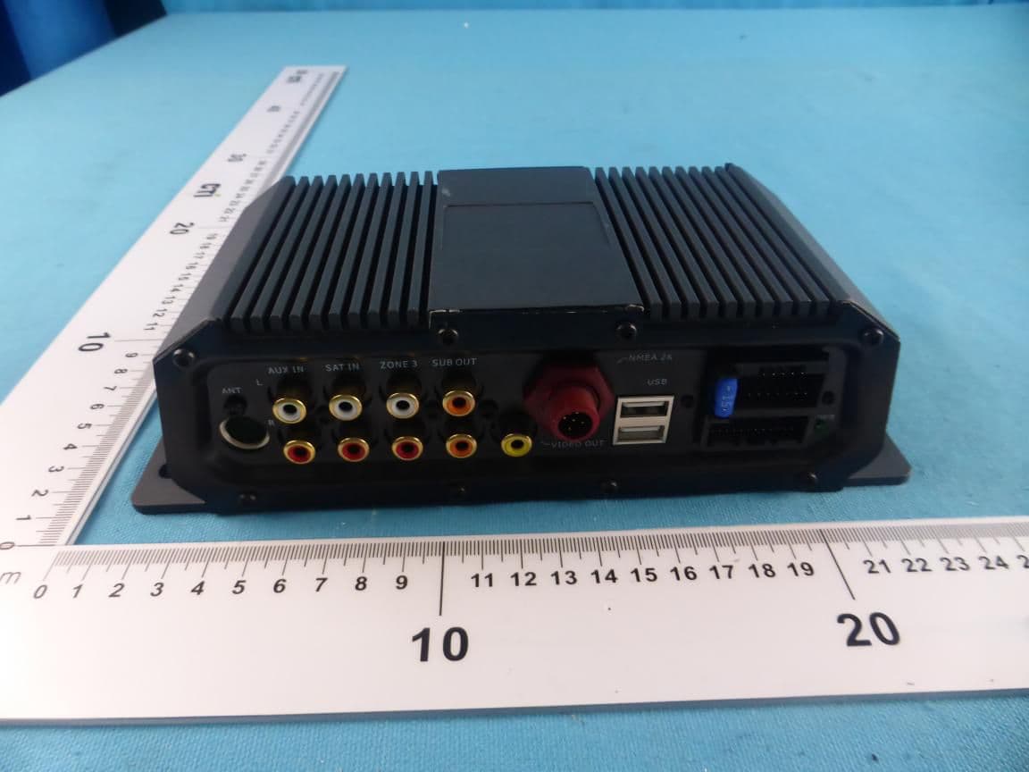
RAYSHGEN2
Sep 17, 2015Marine Entertainment System
Equipment Class
DTS - Digital Transmission System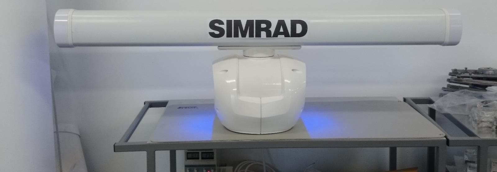
RAYHALO
Apr 09, 2015HALO PULSE COMPRESSION MARINE RADAR
Equipment Class
MRD - Marine Radar